8 Symmetry Systems
1Symmetry is a measure of a system’s ability to absorb rearrangements that cannot be detected. A jigsaw puzzle has none; if you try to interchange two pieces, fit is destroyed. By contrast, square tiles in a square box can be permuted indefinitely without anyone’s noticing. An equilateral triangle which we are forbidden to tum over can be placed on the table three ways—any vertex upward—with no likelihood of these states’ being distinguished.
2 When we turn a polyhedron on an axis, as we did when we were eliciting the great-circle families in Chapter 7, it passes through a sequence of successive states that cannot be told apart. If the icosa axis runs vertex-to-vertex, a complete rotation brings five successive aspects to the fore, each indistinguishable from its predecessor. Each mid-edge axis yields two indistinguishable positions, and each mid-face axis three. So the three great-circle families correspond to three groups of rotational symmetry, and it is not surprising that we can discover symmetries in the inter- relationship of the great circles themselves. In fact, the icosahedron’s thirty-one great circles can be completely specified with the help of a small triangular module, shown in Diagram 8.1. Systematically rotated and reflected six times per spherical icosa face (thus, times per sphere) it reconstitutes the entire great-circle system. This little triangle thus contains all the information we need to subdivide a sphere with symmetrical great-circle systems. Any further subdivisions we may execute within the symmetry triangle will likewise be propagated throughout the system. The symmetry triangle is thus a kind of geodesic DNA molecule, and so long as we are concerned with spheres we may confine our interventions to its minute terrain, in confidence that the rest of the system will reproduce them exactly.
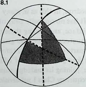
4 The octahedron has a corresponding symmetry triangle, which covers not but of its spherical area. Inspecting a spherical tetrahedron likewise, we discover a symmetry triangle that comprises of it. Since it can be shown that these three polyhedra—icosahedron, octahedron, tetrahedron—contain the entire available array of great-circle symmetry systems, there are no other cases we need to consider.
5 It is helpful to think of the polyhedron simply as a device to help us find systems of symmetry.
6 You are standing at the center of a polyhedral structure. You observe the repeating faces, the uniformly radiating edges, the equidistant vertices. These locate the reference points of omni-symmetry. A vertex, a face center, a mid-edge, comprises their minimum set. The little right-angled triangle so marked out—the symmetry triangle—defines all the polyhedron’s capacity for changes-that-do-not-make-any-difference. Its corners are the poles of symmetry, and if we could locate and specify them somewhere on a single polyhedral face, we should have control of the whole omnidirectional array. To see how this might be done, we shall imagine sightlines from the center of the system and find an economical way to specify them.
7 The great sphere of the sky, a man-made geodesic sphere—it doesn’t matter which we think of: the sightlines are equivalent. The sky has one advantage: it frees us from error in locating the center. You are always at the center of the celestial sphere.
8 We can’t see the whole sphere, but it suffices to see the upper half of it. Imagine an unimpeded horizon, up from which arches the hemispherical bowl. One point on this bowl is perfectly unambiguous, the point directly overhead and equidistant from every point on the horizon. Call it .
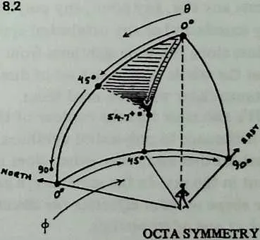
10 We can now designate any direction we choose with the aid of just two numbers. The first number is a compass direction: zero if we are facing north, an increasing number of degrees as we turn counterclockwise from north. The second number also specifies degrees: zero at the zenith, 90° at the horizon, other figures in between. Thus 0,45 designates a unique direction: north, and halfway from zenith to horizon. The comers of the octahedral symmetry triangle are at (see Diagram 8.2; the derivation of this last figure will be explained later).
11 Within the symmetry triangle we may specify in the same way additional points, each with its pair of numbers. We can choose them so that they locate whatever great circles we intend to use, and the vertex points for the geodesic breakdown we plan to employ. Each point designates a sight-line, and what we shall have specified is a cluster of sightlines which contains all the information we need to build a geodesic structure. The symmetry triangle and the cluster of points it contains would simply be reproduced, over and over, until the whole hemisphere was contained—or the whole sphere, for that matter.
12 If you were standing at the center of a man-made geodesic hemisphere you would see the vertex points these sightlines designate, all joined by structural members in triangular arrays. With a little study you could locate the boundaries of an enclosing symmetry triangle and verify that it was the module of repetition.
8.1 Envelope Contours
13We are now about to derive advantage from the fact that we have directed our reference sightlines at the sky instead of at something more accessible like a planetarium ceiling. The advantage inheres in the fact that the sky has no definite distance. Celestial locations are nothing but a set of distance-less directions. Despite the three-dimensional ambience, two coordinates, not three, will suffice to locate any star, any point, any polyhedral vertex. Big or small, any icosahedral or any octahedral system disposes its reference points along the same sightlines from the center. We can therefore treat the whole system as a set of directions and invoke the distances later when we need them.
14 It’s also clear that the contour of the bounding surfaces makes no difference to polyhedral sightlines. The fact that some stars are much further away than others does not affect their relative placement in the sky. In the same way, a geodesic envelope may be of any shape without affecting the direction in which we sight to look at one of its vertices.
15 Provided the structural members were thin enough for their apparent width to provide no cues, it would be quite impossible for an observer at the center of a man-made structure to tell whether he was surrounded by a geodesic sphere or a geodesic egg. In the former case his eye’s distance from every vertex would be the same, in the latter case it would vary, but, given a structure so refined its members looked like ruled lines, these two cases would display exactly the same angular symmetries.
16 In separating distance from direction, we have taken a step of great potential usefulness. First, we know better what we shall be about when we execute a geodesic breakdown. The breakdown will be a little cluster of sightlines, a local symmetry occupying one symmetry zone of the great polyhedral symmetry, and repeated as often as the structure we envisage may require. The envelope of that structure will intercept our system of directions at various points. These are the points that will be joined by struts, and the length of the struts will depend wholly on the size and contour of the dome we want to make. Specify these, and from a table of angular sightlines it is simple to calculate the distances.
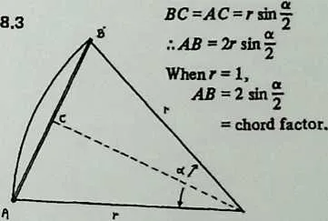
18 It is evident from Diagram 8.3 that if is the angle between the sightlines that lead to two vertices, and is the distance of each vertex from the center (the uniform radius, in the case of a spherical system), then the strut length between the points is multiplied by , twice the sine of half the angle. Twice the sine of half the angle is called a chord factor, because the strut is a chord and we have here one of two useful factors of that chord, the other being the radius. Geodesic designers have worked with chord factors ever since Fuller introduced the concept in the early 1950s. Tables of chord factors, containing as they do the essential design information for spherical systems, were for many years guarded like military secrets. As late as 1966, some icosa figures from Popular Science Monthly were all anyone outside the circle of Fuller licensees had to go on. Now, thanks largely to Lloyd Kahn’s Domebook 1 (Los Gatos, Ca., Pacific Domes: 1970) [Kha70] and Domebook 2 (Bolinas, Ca., Pacific Domes: 1971) [Kha71] chord factors for at least small-to-medium structures are fairly accessible.
19 But concentration on chord factors—the information a constructor ultimately wants—has concealed the great usefulness of the angles from which they are derived. If we know the chord factors for a sphere of a given breakdown and frequency, we can proceed to duplicate it in any practical size. But if we know the sighting angles, we are no longer restricted to spheres. By allowing the radius to vary harmoniously from point to point, we can derive chord factors for a dome of any useful shape. There is no need whatever for geodesic structures to be spherical.
20 What we are after, therefore, is a local cluster of symmetrically disposed points, their symmetries expressed as angles between sightlines from a common center. Once we have our cluster of points, which will be denser for higher-frequency breakdowns, and have made a table with sighting angles for each, we shall need only a procedure for determining the chordal distances from any point to its neighbors, whether they are at the same distance outward or not, and we shall be equipped to design geodesic structures of any shape we please.