::: center
Order in Space
:::
::: titlepage
Order in Space
A Design Source Book
Kieth Cricthlow
Thames & Hudson | London
ISBN: 978-0500340332
ISBN-10: 0500340331
Updated: 2024-12-16
:::
¶ Dedication
To
my wife and all my family
and Buckminster Fuller,
without whose inspiration this book would not have been
The greater part of the work contained in this book was completed in the summer of 1965, and the presentation and format were conceived by the author as a working tool for students of the subject and in particular for the World Design Science Decade.
::: flushleft
© Keith Critchlow 1969
All rights reserved. No part of this publication may be reproduced, stored in a retrieval system, or transmitted, in any form or by any means, electronic, mechanical, photocopying, recording or otherwise, without the prior permission of the publishers.
Printed and bound by Jarrold and Sons Ltd. Norwich
500 3403 31
Copyright
ENCODED IN THE UNITED STATES OF AMERICA
:::
¶ Preface
Conditions are not invariable; terms are not final. Thus the wise man looks into space, and does not regard the small as too little, nor the great as too much; for he knows that there is no limit to dimension.[1]
The material contained in this book represents one way to approach order in space. The growth in understanding of spatial order seems to follow closely man s own evolution as a conscious being. First as a tool of orientation, the where of things, and eventually becoming the how inherent in things.
Pattern has never been the exclusive possession of any one field of human activity; order as pattern seems to have universal meaning.
The primary idea of order and number is one basis for understanding our universe.
To study space without stressing time might seem inadequate in a post-Einstein world. But even space-time is a separation from the consciousness that regards it. We study aspects to assist us in grasping the whole.
I would like to present a few differing points of view as to what space is:
The fundamental element of this cosmos is space…Its nature is emptiness and because it is empty it can contain and embrace everything…Space is the precondition of all that exists…[2]
Thirty spokes converge upon a single hub;
It is on the hole in the middle that the use of the cart hinges.
We make a vessel from a lump of clay;
It is the empty space within the vessel that makes it useful.
We make doors and windows for a room;
But it is these empty spaces that make the room livable.
Thus while the tangible has advantages
It is the intangible that makes it useful.[3]
In relativistic cosmology, the geometrical properties of space are directly related to the distribution of matter. One of Einsteins essential ideas was that gravitation is not merely influenced by the distribution of matter, but is determined by it.[4]
The determining condition of space enables the existing universe to acquire a structure of position, size, shape and relative motions.[5]
To return to Govinda: we can neither imagine an object or being without space. Space, therefore, is not only a conditio sine qua non of all existence, but a fundamental property of our consciousness…Our consciousness determines the kind of space in which we live. The infinity of space and the infinity of consciousness are identical…The way in which we experience space, or in which we are aware of space, is a characteristic of the dimensions of our consciousness.
The work presented here represents certain direct relationships in space and the principles underlying them. As Einstein said: We only know energy when it is exteriorized. Here we are dealing with exteriorized functions of space.
The book is designed for the visually orientated. It is a manual of space functions. It aims to show experimental ways in which related division is possible in space by a process of economy or least effort between elements. For example, if one holds up the index finger of each hand, the tips of those fingers cannot be reduced to less than a point each and the relationship between them a line.
Mechanisms, architecture, applied science and all technologies imply designers. These designers need to know the basic freedoms of their constructions space. A command of the functions possible in space becomes progressively more necessary in a shrinking planet, which points to the real problems; between man and man, man and his universe and mans continued existence. They are matters of the assessment of essentials. One of these is that human existence is never less than multi-dimensional. In a unified world spherical thinking is a prime requisite for both accuracy and understanding. In the macrocosm, nations are no longer flat but an integral part of a curved surface dependent for their existence on identical curves meeting at the boundaries. In the microcosm each of us begins life as a sphere even the eyes that read these words are basically spherical.
Yet we are taught so soon to project our minds on to the flat and even trained to think of geometry at school as starting from the flat and projecting up into the solid. The truth is, we are finite and we exist in a finite universe. We educe the infinite in the same way: we start in the round and can project to the flat-infinite plane, which according to modern theory is also to be conceived as returning on itself, not continuously away to infinity.
The more natural procedure, as followed by Einstein. Infeld and Hoffman, is to suppose that matter acts as though it were a distribution of mass-singularities in space, so that there is no need to introduce, artificially, a continuous distribution of matter in space; it is enough to study the relationships between attracting “singular points´´.[6]
There are many routes to the understanding of complex ideas. Here we are to follow the experimental or empirical where the hand, eye and mind can all work together. We take the unorthodox route of regarding a point as physically real; its relative size being dependent on human experience. The point then, can be handled, visualized and seen to occupy a position in space. By manipulation we can study its behaviour singly and collectively. Hence all the illustrations in this study are directed towards experiment or model-making.
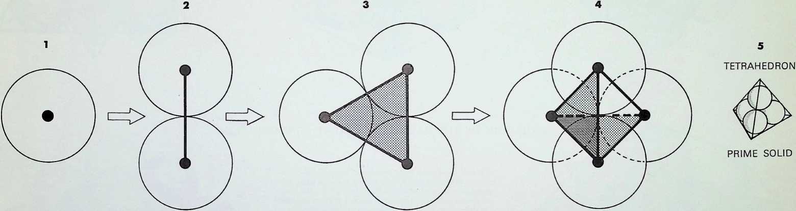
Without predetermining the most appropriate form for the ‘point’ we can take a minute version and see what volumes it describes by tracing it systematically through space.
If a point moves in an unchanging direction, from a starting position, a trace of its path describes a line the so-called first dimension, 1. Moving the line in any other than the first direction describes a planar trace the so- called second dimension, 2. The trace of the third change in direction describes a ‘solid’ the so-called third dimension, 3.
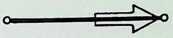
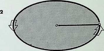
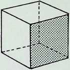
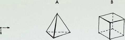
There are three fundamental ways in which the three moves might be made: the first and most economical provides the prime solid, the tetrahedron[7] the four-faced pyramid; the second and most commonly used results in the cube; the third, involving a cyclic movement or a rotation through each dimension, results in the sphere.
The tetrahedron, minimally structured, is the strongest of these solids, being most able to resist external forces from all directions. It has the greatest surface area for volume of all polyhedra.
The sphere has the least surface area for volume and is most suitable for restraining internal forces (hence the bubble).
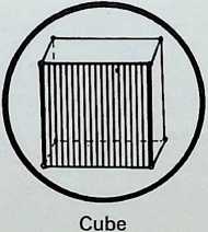
The cube represents the transitional phase between the two, and is a sociable or close-packing unit.
The criteria of spatial and structural economy i.e. least expenditure of energy (or moves) to accomplish ends will be applied hierarchically throughout this book.
To return to the initial proposition: what physical form can be given most appropriately to the point for the exploration of ordered moves in space?
Any form, however random, if completely rotated on its centre of gravity eventually describes a sphere at its extremities, hence the sphere is the most economical form that is non-exclusive. The sphere thus seems the most suitable form to give to the point as it has complete rotational symmetry and is least biased. Henceforth the point will therefore be referred to and shown as a spherepoint.[8]
THE MOVES INTO THE DIMENSIONS
A
THE MINIMAL MOVEMENT
Point of departure
o
TETRAHEDRON
B
THE MEDIAL MOVEMENT
Point of departure
CUBE
C
THE MAXIMAL MOVEMENT
Point of departure


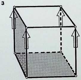
THE THREE BASIC WAYS AND THEIR RESULTING FORM
We now take a closer look at the most economic unfolding of the dimensions.
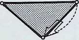
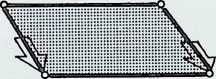
If a line is considered to have a spherepoint at each end, then the line represents, at a minimum, a displacement of the diameter of one spherepoint. 1. The line can be regarded as the track of a spherepoint which has moved at least its own diameter. The spherepoints cannot be closer. Two spherepoints are shown here. 2. with a line between their centres, to represent their fundamental relationship.
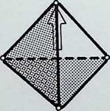
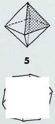
The minimum condition to describe a plane is that three spherepoints should be set in any other relationship than in a straight line, 3. As before, applying the most economic conditions, each spherepoint being its own bodily distance from its neighbour, we describe a plane resulting in an equilateral triangle between the centres of the spherepoints. Adopting the same criteria and following the same procedure. we describe solid space with the fourth and final spherepoint, 4: the result is a four-faced pyramid, the tetrahedron. There are six links possible between the four centres of the spherepoints, these provide the six edges of the tetrahedron. This last pattern of spherepoints represents the greatest number of equal spheres that can be brought into simultaneous contact. Each one touches all the others. The final drawing, 5, shows a perspective view with the bounding lines of the tetrahedron lying outside the four spherepoints.
¶ THE ECONOMIC UNFOLDING OF THE DIMENSIONS OF SPACE
+:------------------+:-------------------------------------------------------------------+:-------------------------------------------------------------------------------------------------------------------------------+:---------------------------------------------------------------------------------------------------------------------------------------------------------+
| POINT | LINE | PLANE | ::: minipage |
| | | | > SOLID |
| Primacy and unity | First move, the | Second move, the threeness. | > |
| | | | > Third move, the fourness |
| | | | ::: |
±------------------±-------------------------------------------------------------------±-------------------------------------------------------------------------------------------------------------------------------±---------------------------------------------------------------------------------------------------------------------------------------------------------+
| The morphic point | ::: minipage | ::: minipage | ::: minipage |
| | > twoness. has inherent the third factor, the relationship or line | > produces our first and only structural polygon, the triangle; this bounds a plane. Three points: three lines: three contacts | > becomes the most simple and primary solid, the tetrahedron. The relationships increase to give: four vertices, six linear edges, four faces and twelve |
| | ::: | ::: | ::: |
±------------------±-------------------------------------------------------------------±-------------------------------------------------------------------------------------------------------------------------------±---------------------------------------------------------------------------------------------------------------------------------------------------------+
points of contact
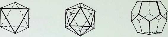
¶ EVOLUTION OF THE BASIC SPHEREPOINT CONFIGURATIONS
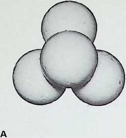
A Four spheres in tetrahedral configuration are the greatest number than can be in simultaneous contact
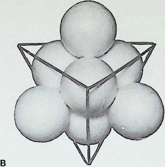
B The tetrahedron, outlined on its edges, with a second set of spheres introduced into the interstices: eight spheres in all
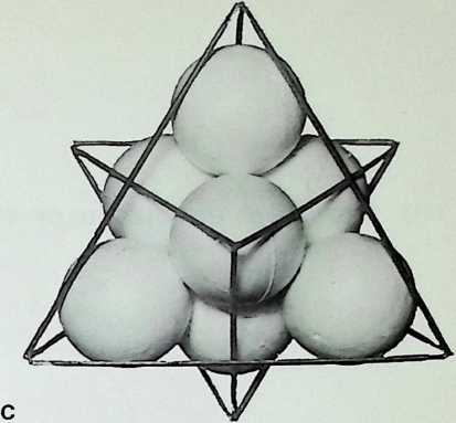
C The second set of spheres shows that the tetrahedron is its own dual i.e. the lines joining the centre points of the faces repeat the original figure
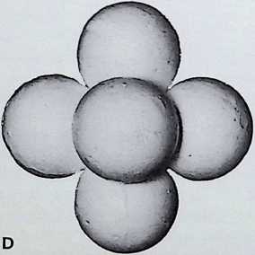
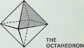
D The next most economic regular grouping of spheres is six in octahedral configuration; each sphere touches four others
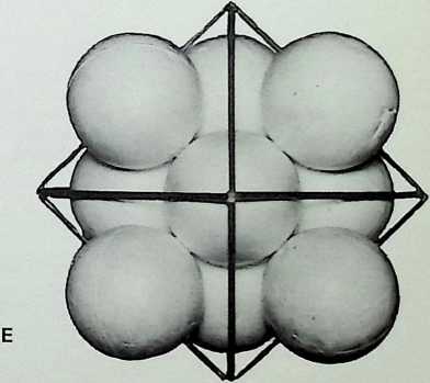
E The octahedral group outlined with edges, with eight additional spheres in the interstices
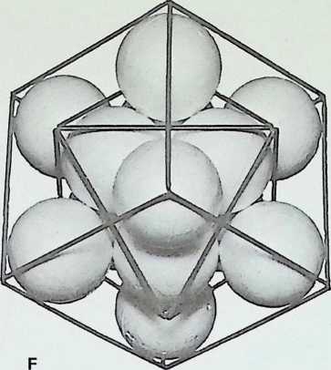
 F When the edges of the second set of spheres are outlined, the cube emerges as the dual of the octahedron: the lines joining the centre point of the faces of the octahedron result in a cube. Conversely, the lines linking the centre of the faces of a cube result in an octahedron
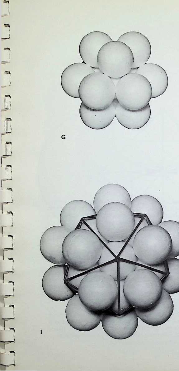
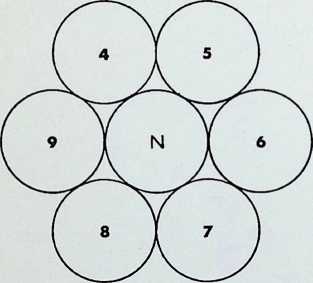
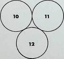
G The closest packing of equal spheres around a nucleus of equal size gives the dymaxion or cuboctahedron. The nuclear sphere is surrounded by twelve spheres, each touching four neighbours in addition to the nucleus
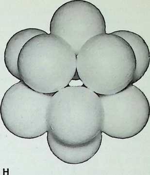
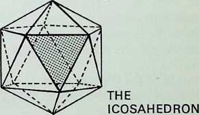
H The grouping without the nucleus tends to close into the triangulation of the icosahedral grouping: the twelve spheres are in closer configuration, each touching five others
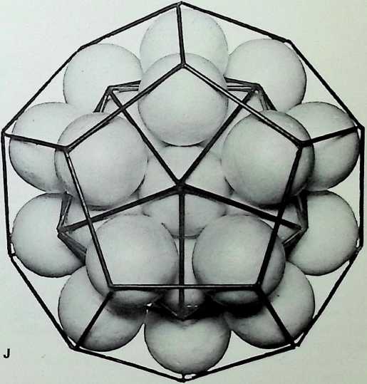
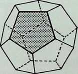
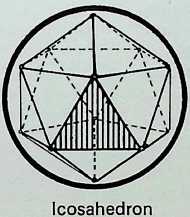
I The icosahedron, with its edges outlined, shown on its 5-fold axis with a sphere introduced into each interstice- 32 spheres in all
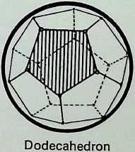
J The added set of spheres, when outlined, show that the regular dodecahedron is the dual of the icosahedron. This demonstrates a hierarchy of the five regular or Platonic solids by the criteria of numerical and structural economy
Photos: Tony Jenkins
From the arrangements of spherepoints in the photographs the following principles can be adduced:
-
Four equal spheres are the greatest number that can be in simultaneous contact - the first regular pattern:
-
six equal spheres are the next regular pattern, with each sphere touching four neighbours:
-
twelve equal spheres may surround and touch a nucleus of equal size. (When the nuclear sphere is removed the form contracts into the third regular configuration. with each sphere touching its five neighbouring spheres; this will be shown later to be part of a threefold transformation of the twelve degrees of freedom.)
Introducing additional spheres into the interstices of the three regular triangulated patterns generates the dual solid of each. In the first case, the tetrahedron is its own dual: in the second case, the cube is the dual of the octahedron; and in the third case, the regular dodecahedron is the dual of the icosahedron. This provides five regular solids from three triangulated close packings of equal spheres by the introduction of a second set of spheres in their interstices.
The next exploration illustrates another method of arriving at the same hierarchy of solids, adopting the same principles of economy.
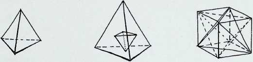
The points of contact between spherepoints rather than their centres are to be joined by lines.
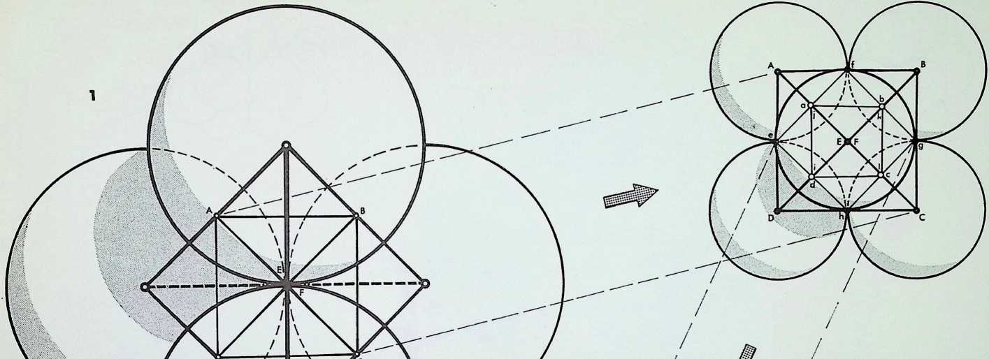
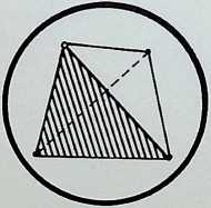
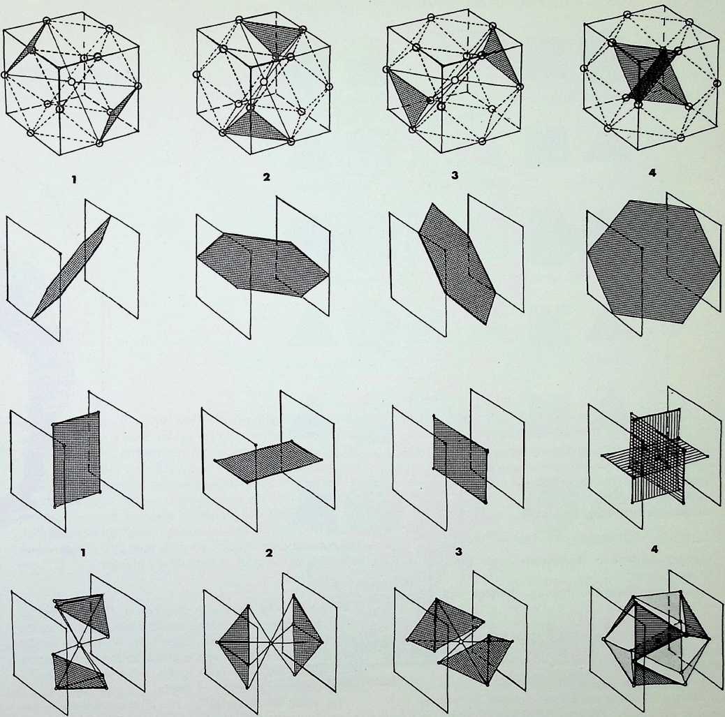
In drawing 1 we see that if the six points of contact (A, B, C, D. E and F) between the first four spherepoints are joined (E and F being furthest from and nearest to the eye respectively), the result is the octahedron, a figure composed of eight equilateral triangles. As the apices of the octahedron are exactly half-way along the edges of the basic tetrahedron formed by joining the centres of the spherepoints, we can regard the octahedron as the first octave subdivision of the tetrahedron.
In drawing 2 we see that if the octahedron is isolated and its apices are simultaneously expanded to become spherepoints in close-packed relationship one to another, then the lines linking the twelve points of contact of these spherepoints (a. b. c, d, e. f; g. h, i, j, k. I) from the figure called the cuboctahedron, which is made up of a total of twenty-four edges describing eight equilateral triangles and six squares. Professor R. Buckminster Fuller has named the cuboctahedron the dymaxion to stress its exceptional properties of equilibrium. The distance between its apices is identical to that from any apex to the centre of the configuration.
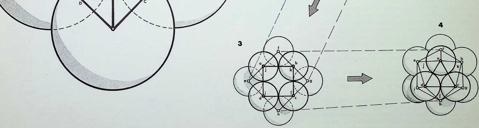
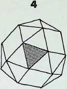
Drawing 3 shows that if the cuboctahedron is isolated and the apices expanded as spherepoints as before, the resulting figure is seen to be stable on only eight faces the triangular relationships and unstable on six faces the square relationships. Triangulation is incomplete. The figure is in equilibrium, but it is unstable because it has no nuclear sphere.
Drawing 4 shows that without this nucleus, the spheres tend to close into a totally stable, triangulated position providing the figure called the icosahedron (a. b. c. d, e. f. g. h. i. j. k, I) which is made up of thirty edges and twenty triangular faces. This is the third and final regular triangular close-packing pattern of equal spheres - regular meaning that all planar, linear and angular relationships are equal (in the plane solid faces, edges and angles).
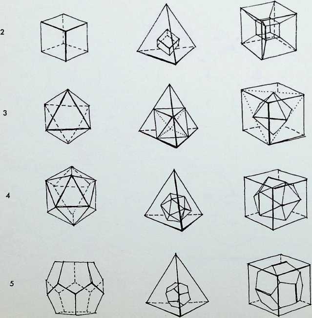
It will be seen from the drawings of the transpositions that there are three sizes of spherepoints shown, each one half of that preceding it three octave subdivisions. Hence the primary solids have been shown in yet another way to be related in a hierarchy of occurrence.

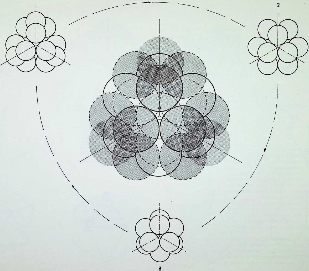
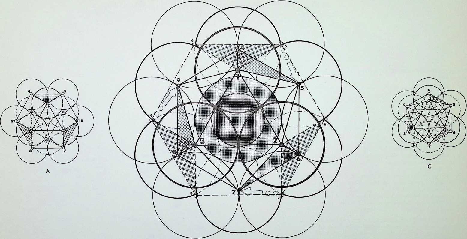
The drawings show the full process of transformation from the twelve spheres in the truncated tetrahedral pattern. 1 (the result of close-packing twelve spheres around the four initial spheres of the tetrahedron, then taking these four away, leaving a hollow core). The closing together of the twelve spheres provides first the cuboctahedral pattern. 2. then the icosahedral pattern. 3.
A full explanation of this closing phenomenon is given in appendix 4.
The central drawing shows all three positions of the transformation, overlaid - the truncated tetrahedron is shaded, the cuboctahedron is in broken outline, the icosahedron is heavily outlined.
The last two phases of this transformation were first recognized by Professor R. Buckminster Fuller who named them the twelve degrees of freedom and demonstrated that the movement between cuboctahedron and icosahedron could take place turning either to the right or to the left. This property is known as enantiomorphic.

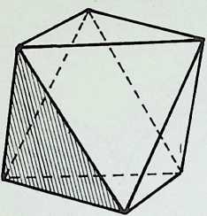
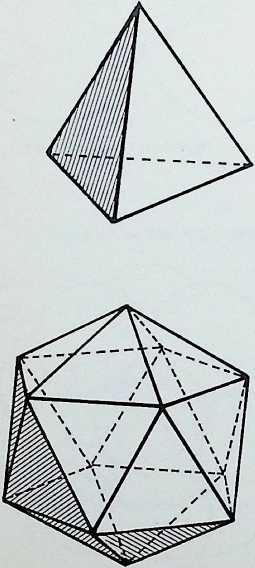
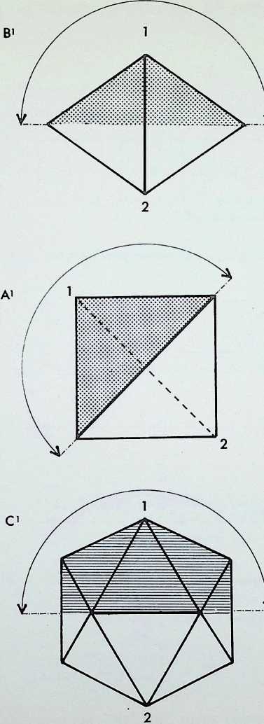
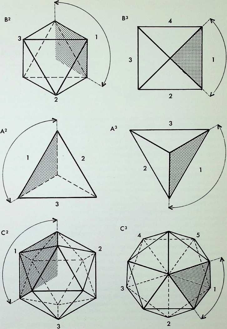
This page demonstrates the properties of symmetry of the three representative (structural) regular solids.
The prime solid, the tetrahedron. A, is shown first in perspective; secondly viewed edge-on. A1, in its 2-fold symmetry (i.e. it can be folded or mirrored only once on what is known as its 2-fold axis); thirdly, viewed face-on, A2, in its 3-fold symmetry; and fourthly point-on. A3, in an alternative 3-fold symmetry. Thus the tetrahedron is described as having 2, 3. 3-fold symmetry.
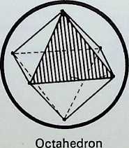
The secondary solid, the octahedron, B, is shown first in perspective; secondly edge-on, B1, in 2-fold symmetry; thirdly face-on, B2, in 3-fold symmetry; fourthly point-on. B3, in 4-fold symmetry. The octahedron has 2. 3, 4-fold symmetry: it is the prime representative of this family of symmetry.
The tertiary solid, the icosahedron, C, is shown first in perspective; secondly edge-on. C1. in 2-fbld symmetry; thirdly face-on. C2. in 3-fold symmetry; fourthly point-on, C3. in 5-fold symmetry. The icosahedron has 2, 3. 5-fold symmetry and is the prime representative of this family of symmetry.
¶ SYMMETRY

h
f
,1
■: J
□
I
2 ll f
„i!
rr
\Ne have already determined the three regular stable triangulated figures the tetrahedron, the octahedron and the icosahedron. Here we are to explore further the relationships between the points of contact of the six spheres making up the octahedral pattern and the twelve spheres making up the icosahedral pattern.
The twelve points of contact of six equal spheres resulted in the cuboctahedron or dymaxion, made up from the eight triangular faces, 1-8.- and six square faces, 1-6. shown here. Regularly assembled, the six square faces make up a cube, the eight triangular faces constitute an octahedron.
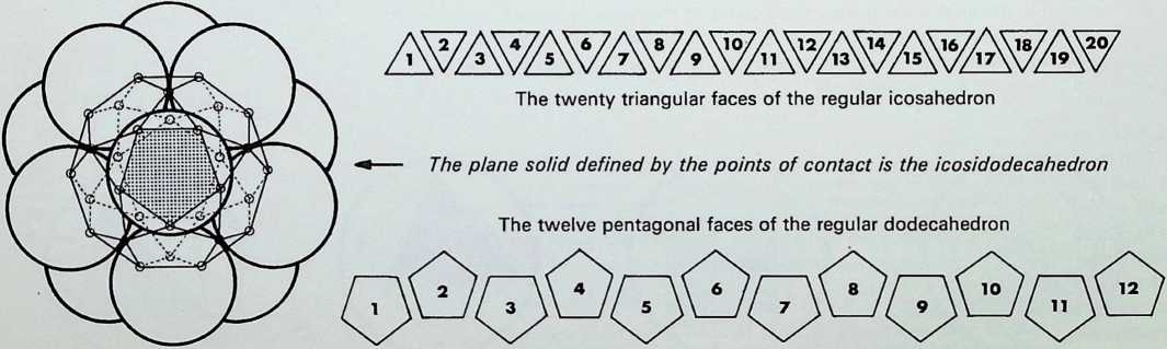
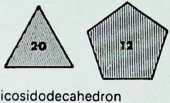
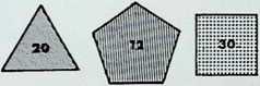
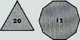
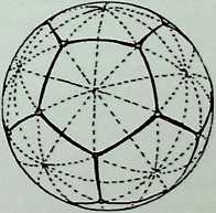
The thirty points of contact of twelve equal spheres result in an icosidodecahedron, made up of twenty equilateral triangles, 1-20. and twelve pentagons, 1-12, shown here. Regularly assembled, the twenty triangular faces make up an icosahedron, the twelve pentagonal faces constitute the dodecahedron.
The tetrahedron, the octahedron and the icosahedron together with the cube and the dodecahedron make up the five regular solids known as the Platonic solids, so called not because they were discovered by Plato but because of the special emphasis he placed upon them in expounding the Pythagorean cosmology in the Timaeus. The figures were regarded as one basis for the structure of the universe. The tetrahedron represented the molecule of fire, the octahedron the molecule of air. the icosahedron the molecule of water and the cube the molecule of earth, while the dodecahedron represented the all-containing ‘ether’ or the heavens.
¶ THE SURFACES BETWEEN THE POINTS OF CONTACT OF THE OCTAHEDRAL AND ICOSAHEDRAL SPHEREPOINT GROUPINGS
THE OCTAHEDRAL GROUPING GIVES
SIX SQUARES AND EIGHT TRIANGLES
The octahedral points of contact
The six square faces of the cube
The plane solid defined by the points of contact is the cuboctahedron
The eight triangular faces of the regular octahedron
The icosahedral points of contact
THE ICOSAHEDRAL GROUPING GIVES TWENTY TRIANGLES AND TWELVE PENTAGONS
THE CUBE
THE
DODECAHEDRON

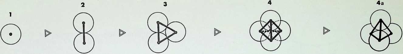
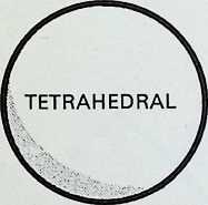
The top line of sketches is a visual reminder of the process adopted in establishing the three dimensions, starting from a point, 1, moving to the line. 2. the plane, 3, and thus to the prime solid. 4 and 4a. the tetrahedron.
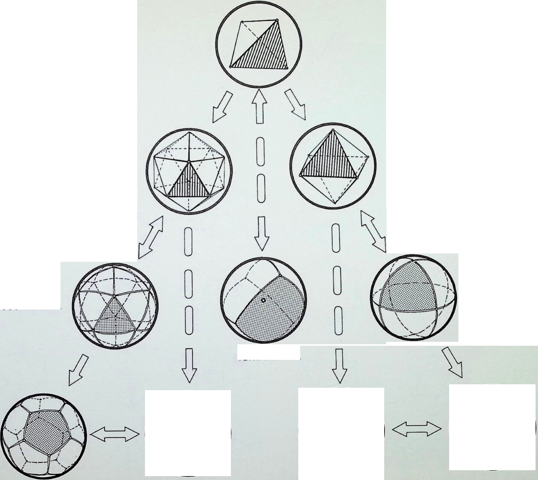
It is possible to display the hierarchy between the five Platonic solids1 by allocating to each a sphere and grouping these in accord with the pattern used to establish the three dimensions.
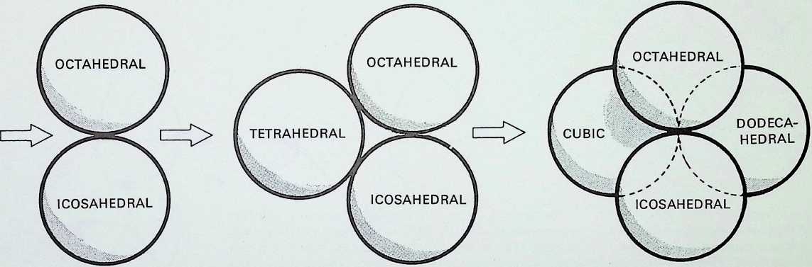
The apices of all the Platonic solids lie in the surface of a circumscribing or containing sphere, shown in the bottom line.
The first of the solids, the tetrahedron, is allocated to the first sphere, in the middle range of drawings. The next two spheres are allocated to the octahedron and the icosahedron as they are the prime representatives of the figures with 2, 3, 4 and 2. 3, 5-fold symmetry (p. 11). Three spheres containing the three triangulated inherently structural Platonic figures are then grouped together. If the two pairs of spheres, containing the prime and secondary representatives of the 2, 3. 4 and 2, 3, 5-fold symmetries,
- e. octahedron and cube with icosahedron and dodecahedron, are placed in close packing, the relationship between the four spheres provides the tetrahedron, completing the cycle and establishing it once again as the master or over solid indicated in the small diagram at the end of this range.
The prime and secondary representatives of the 2. 3. 4-fold symmetrical figures, it should be noted, are duals, i.e. the lines joining the centre-point of the faces of one of the figures results in the other figure. Similarly the prime and secondary representatives of the 2. 3, 5-fold symmetrical figures are duals.
‘Definition of a regular or Platonic solid: a convex polyhedron is said to be regular when its faces are regular and equal, and its vertices are all surrounded alike. If we denote the faces {p}. and those surrounding each vertex {<?}. the polyhedron is described by {p. g}. We can examine the possible values of p and q thus: the solid angle at a vertex has q face-angles, each M - n: these q angles must total less than 2rt so we get 1 - < .
111
This gives us - + - > j. or (p - 2) (q - 2) < 4. Therefore {pg} cannot have any other values than {3. 3}, {3. 4}. {4. 3}. {3. 5} and {5. 3}. which are respectively the regular tetrahedron, octahedron, cube, icosahedron and dodecahedron. See H.S. M. Coxeter. Regular Polytopes. 2nd ed… p. 5 (Macmillan, London).
The first three moves into the dimensions with the
allocation of the regular solids by hierarchy of occurrence
PRIME SOLID
Tetrahedron
REGULAR MEMBERS OF
2, 3, 4-FOLD SYMMETRY
REGULAR MEMBERS OF
2, 3, 5-FOLD SYMMETRY

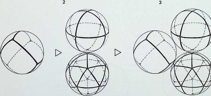
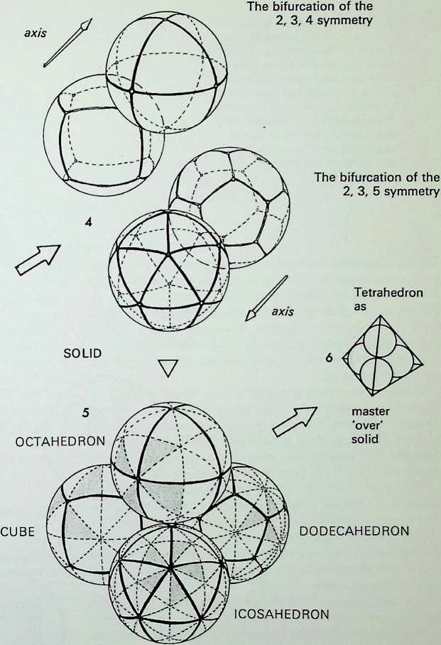
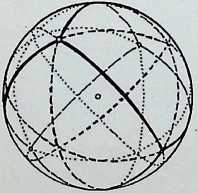
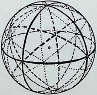
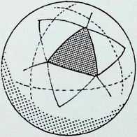
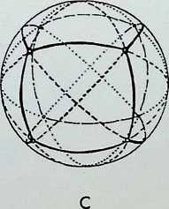
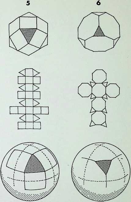
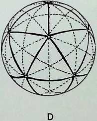
The diagrams on this page trace the same sequence of relationships between the Platonic solids as on the previous page, but here the figures are drawn on the surface of the containing sphere as geodesies: 1 shows the spherical tetrahedron: 2 the paired prime representatives of 2. 3. 4 and 2, 3. 5-fold symmetry in the regular solids - the spherical octahedron and the spherical icosahedron: 3 illustrates these three triangulated regular solids grouped together: 4 shows the pairing of the representatives of
- 3, 4 and 2. 3, 5-fold symmetry in the regular solids.
Figure 5 shows this arrangement in close packing and demonstrates in addition that if each of the outlined faces of the solids are subdivided into their complete symmetries indicated by dotted lines - three out of the six equal triangles (shown shaded) making up the face of one segment of the octahedron will be seen to be identical to one of eight equal triangles making up the face of one segment of the cube, while one of the six equal triangles making up a segment of the icosahedron is the same as one of the ten making up a pentagonal segment of the dodecahedron.2
The triangles (48 in number) making up two 2. 3. 4-fold symmetrical figures are larger but proportionally the same as those (120 in number) making up the two 2. 3. 5-fold symmetrical figures. Their exact relationship is shown later in the book (see page 95).3
Figure 6 represents the completion of the cycle, showing the 2. 3. 4 and 2, 3. 5-fold symmetrical figures making up the master regular solid, the tetrahedron.
-
In the fourth century [ad]{.smallcaps} Pappus observed that reciprocal regular polyhedra. i.e. dodecahedron and icosahedron, can be inscribed in the same sphere in such a manner that the twelve vertices of the former lie by threes on four parallel circles, while the twenty vertices of the latter lie by fives on the same circles. See H.S. M. Coxeter. Regular Polytopes. 2nd ed… p. 88. (Macmillan. London).
-
Hypsicles attributed the discovery of the simultaneously similar circumspheres and inspheres of the icosahedron and dodecahedron to Apollonius of Perga (3rd century [bc).]
-
C. 300 [bc]{.smallcaps} Euclid (xv. 3) demonstrated the reciprocation of octahedron and cube and the converse, together with the dual function of the icosahedron and dodecahedron.
THE SPHERICAL SYMMETRY OF THE FIVE PLATONIC FIGURES RELATED TO THE FIRST THREE MOVES INTO THE DIMENSIONS
POINT
Tetrahedron as point unity
LINE
Octahedron Icosahedron as first bifurcation
PLANE
Tetrahedron
Octahedron Icosahedron as primary structural triangle
FULL TETRAHEDRAL CYCLE SHOWING GREAT CIRCLE VERSION OF BASIC SYMMETRIES
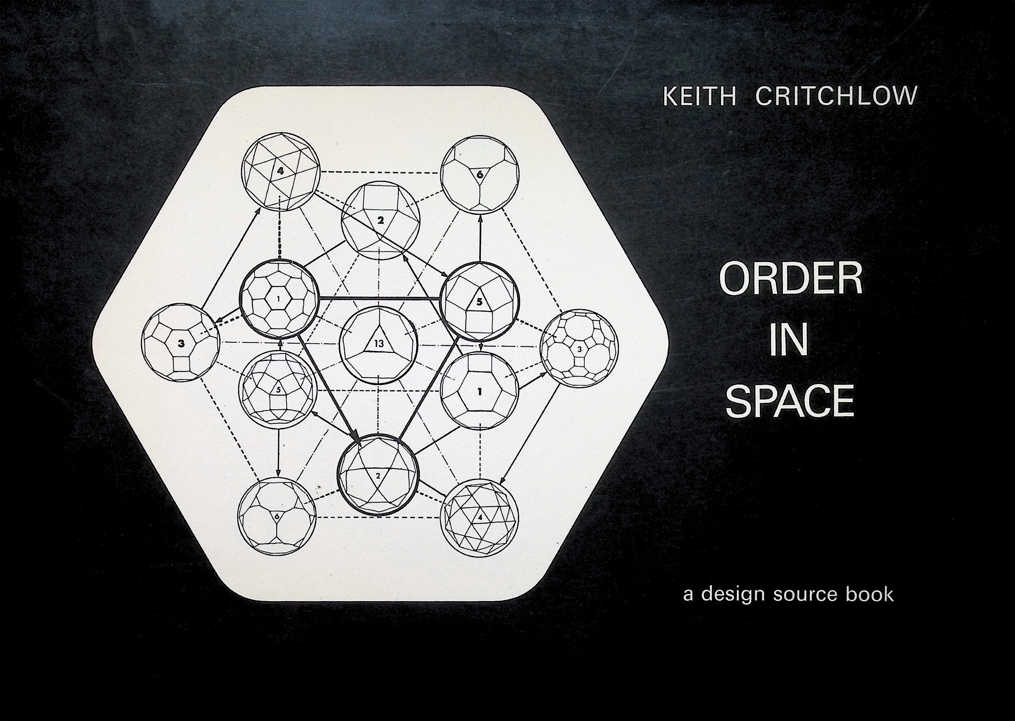
The drawing illustrated here is a speculative attempt to show the hierarchy and relationship of the five regular solids and their spherical counterparts to the tetractys. a triangular pattern made up of ten units - which was apparently the basis of Pythagorean harmony. In ancient Greece, mathematical problems are thought to have been demonstrated with physical objects, usually pebbles (given organized form in the abacus).
These pebbles were grouped to form figures - triangles, squares, hexagons, etc. providing what are known as figurate numbers’. Thus when three pebbles are grouped to form a triangle, three is the figurate number, four in the case of a square or a rhomb, seven (i.e. a nucleus surrounded by six pebbles) in the case of a hexagon, etc.
Triangular numbers can be considered as the base of tetrahedral numbers that is numbers to the power of three. The economic significance of the tetrahedral rather than the standard cubic relationship of numbers has been particularly emphasized in the work of Professor R. Buckminster Fuller the tetrahedron being an inherently ‘stable form of ‘powering, the cube unstable.
The arrangement here shows the figurate number ten as a triangle.
The five regular solids and their spherical counterparts are allocated spheres, and relationships between them are suggested by arrows. The octahedron and the cube take up the right-hand side of the figure, the icosahedron and the dodecahedron the left-hand side. The tetrahedron is both at the apex and the centre, being the master solid. The whole tetractys pattern can be given tetrahedral form, in which case the figurate number will be twenty not ten. i.e. twenty spheres would be required to build up the whole pyramid. The triangular number 10 provides the base, the tetrahedral number 20 the whole pyramid. It could be speculated that the further fifteen spheres might have been allocated the thirteen semi-regular or Archimedean solids plus the spherical rhombic triacontahedron and spherical rhombic dodecahedron.1 (Twenty is also the greatest number of equilateral triangles that can subdivide a sphere, giving the faces of the icosahedron.)
The relationship between triangular and tetrahedral numbers is shown below:
| units | ||||||||||
sequential numbers |
||||||||||
| triangular numbers | ||||||||||
| tetrahedral numbers |
1 See fig. 3 on page 43; these figures are an equilibrium between the octahedron and cube and the icosahedron and dodecahedron. See page 53, drawing C.
¶ THE REGULAR TETRACTYS
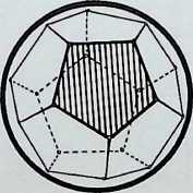
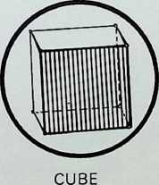
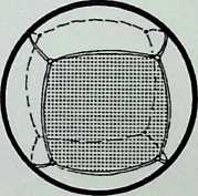
Progression of regular polyhedra, first as situated within a sphere, second developed as surface division of sphere, showing a hierarchy from top and centre - with tetrahedron followed by octahedron and icosahedron, which in turn generate the cube and dodecahedron; as a dual the points of one are at the face centres of the other.
TETRAHEDRON
OCTAHEDRON
ICOSAHEDRON
OCTAHEDRAL
ICOSAHEDRAL
DODECAHEDRAL
TETRAHEDRAL
DODECAHEDRON
CUBIC
HISTORICAL COMMENTARY
The whole triangle is in the ten- unit shape of the Pythagorean tetractys, a figure with four units per side and a total of ten units. This pattern may bear a relation to Pythagorean teaching as it is believed that the cosmology of the Timaeus was Pythagorean.
It was from the Timaeus and its author, Plato, that these figures were named the Platonic solids
This chart illustrates the inter-relationship of the five Platonic solids.
The figures in the upper line (A, B. C. D, E) predominate in the inter-relationships.
C D E
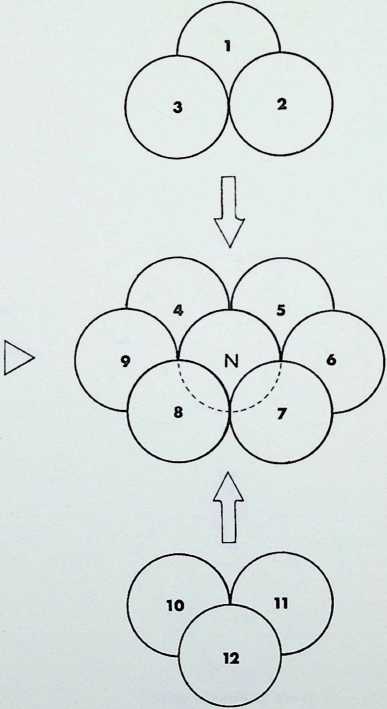
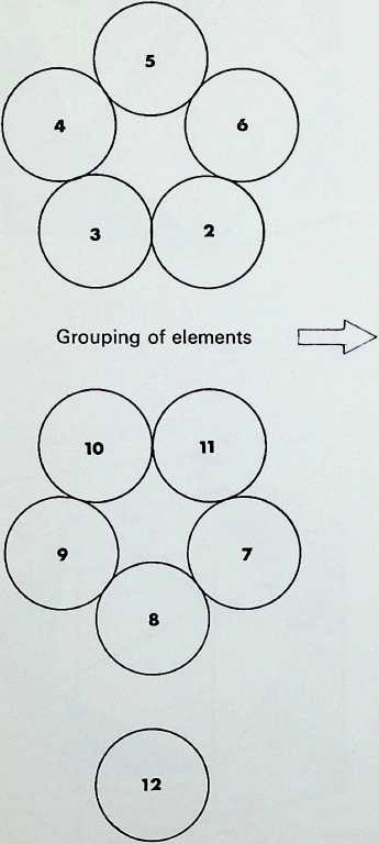
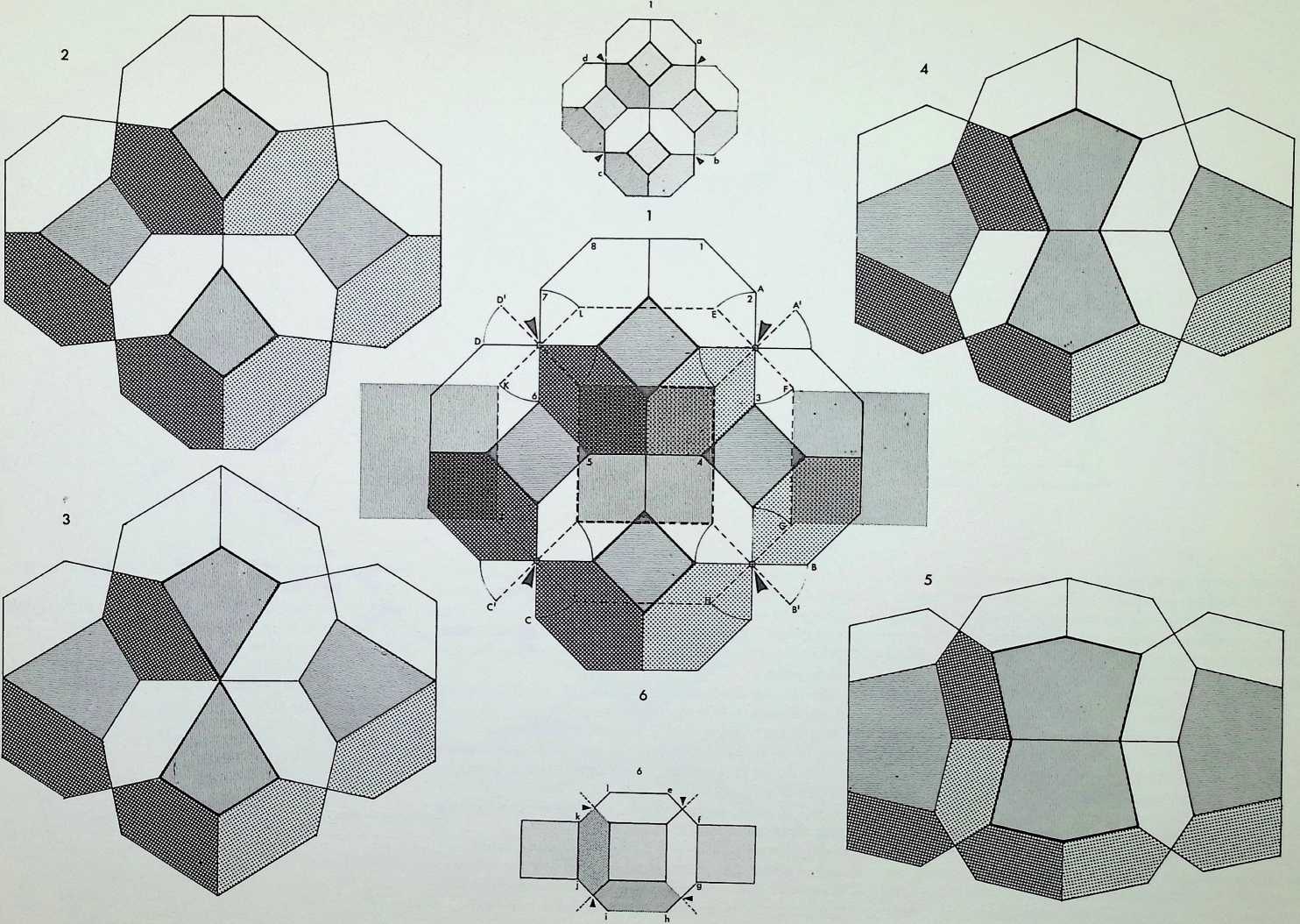
The cuboctahedron or dymaxion displayed on pages 11 and 13 was made up of twelve equal spherepoints around an identical nuclear sphere. The twelve spheres are shown here first in plane or figurate number (two triangles and a hexagon containing three and seven spherepoints respectively), secondly obliquely, showing how they are combined in close packing to make up the cuboctahedron or dymaxion.
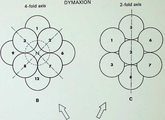
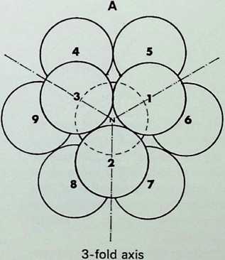
The triangular groups, it should be emphasized, are mirrored arrangements one through the nuclear sphere of the other. All three symmetrical views of the dymaxion are shown on the right: the first. A, is in the 3-fold axis, with the triangular face towards the eye; the second, B. is the 4-fold axis with the square face towards the eye; C shows the 2-fold axis, with a sphere towards the eye.
Elements close in
I
I
with thirteenth as nucleus
to give closest packing
CUBOCTAHEDRON or
Resultant grouping made up of square and triangle relationships. All intercentres are equal linear distances


 THE COMPOSITION ASSEMBLY AND SYMMETRY OF TWELVE EQUAL SPHERES AROUND AN EQUAL NUCLEUS
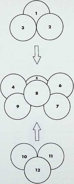
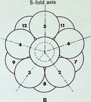
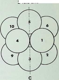
The icosahedral pattern of twelve spherepoints can be assembled most conveniently in the ways indicated in the two columns of drawings on the left - the pattern can be considered as consisting either of four layers, made up of two isolated spherepoints and two groupings of five spherepoints, or it can be broken down into three layers, the two extreme ones of three spherepoints each, the middle one a buckled hexagonal grouping.
The drawings on the right show the icosahedral pattern viewed from its 3-fold (A). 5-fold (B) and 2-fold © axes.
The numbering of the spherepoints is constant throughout the series of drawings.
The elements move in without nucleus
2-fold axis
The resultant grouping is the icosahedron. The linear relationships give total triangulation, with twelve points, thirty linear edges and twenty planar faces
¶ THIS ARRANGEMENT OF TWELVE EQUAL SPHERES CAN ONLY CONTAIN A SMALLER NUCLEUS

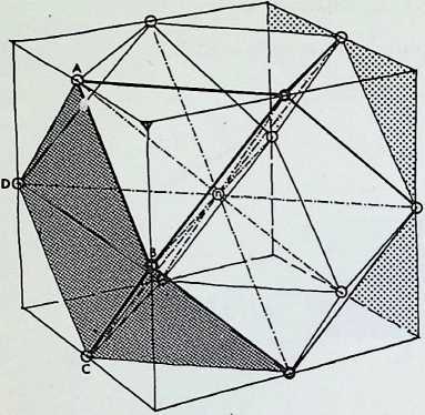
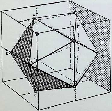
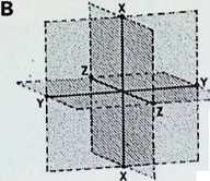
The two twelve-point configurations are shown in the diagrams on the left, contained for convenience within cubes. The upper drawing shows the cuboctahedron or dymaxion with four of its twelve apices (e.g. A. B, C. D) lying half-way along four of the leading edges of the enclosing cube. The lower drawing shows the contracted twelve-point configuration, now in icosahedral pattern, with the points A. B. C and D still in the face of an enclosing cube, but whereas D and B have remained in the same face as before, A and C have moved respectively into the upper and lower faces of the cube. All the square faces and all the edges of the cuboctahedron lie in the faces of the enclosing cube, whereas no faces and only six edges of the icosahedron lie in the face of its containing cube.1
In the top row of diagrams, the pairs of triangular faces of the cuboctahedron are shaded: in each instance these are the faces diagonally opposite one another, i.e. those lying on one of the four diagonals of the enclosing cube. This shows that identical regular tetrahedra can be built up on these faces with a common apex corresponding to the centre of the cube. The cuboctahedron can thus be regarded as being composed of eight tetrahedra and six half-octahedra. The volumetric significance of this composition has already been noted by Professor R. Buckminster Fuller.[9] [10]
In the second row of drawings, the four equatorial hexagons are shown, i.e. those that result by cutting the cuboctahedron in half.
In the third row, the significant rectangles formed by linking the pairs of points lying opposite one another on the enclosing icosahedron to the faces of the cube are shown both separately (1, 2. 3) and assembled (4). These rectangles are in Golden Mean ratio, i.e. their sides are in the relationship of 1:1 -618 . . . etc. Fifteen identical such rectangles could be described within one icosahedron: only those three which are parallel to the faces of the enclosing cube (the XYZ coordinates) are shown here. Particular usage of this pattern was made by Rudolf Laban for spatial appreciation in dancing, the notation he devised for this purpose has since been adapted for ergonomic studies (see pages 86-89).
In the contraction of the twelve-point configuration of the cuboctahedron to an icosahedron, the square face ABCD became two equilateral triangular faces ABD and BDC. folded along the edge BD. If these folded triangles and those correspondingly opposite are linked (as shown in the bottom row of diagrams) through the common centre of the solids, the figure formed can be seen to be made up of four identical, but not regular, tetrahedra. In the fourth drawing of the series the pairs of folded triangles are left unshaded, the shaded triangles are the eight remaining faces of the icosahedron, that is those faces which are constantto both the cuboctahedron and the icosahedron.
The edge lengths of the cubes are v/2 in the top drawing and [k/5]{.smallcaps} + 1
Thus far we have studied relationships between the seven solid configurations, the five Platonic:
tetrahedron (four equilateral triangles)
octahedron (eight equilateral triangles)
icosahedron (twenty equilateral triangles)
cube (six squares)
dodecahedron (twelve pentagons);
and the two Archimedean semi-regular solids;1
cuboctahedron or dymaxion (eight triangles and six squares)
icosidodecahedron (twenty triangles and twelve pentagons).
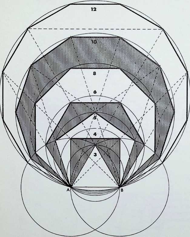
The faces of all these solids are made up by the use of three geometrical figures: the triangle, the square and the pentagon.
Only seven polygons or shapes, singly or in combination, are needed to define the primary orders’ of ’surface’ or of solid space. These 3. 4. 5. 6. 8. 10 and 12-sided polygons are shown together here in the large diagram; they are all generated from two primary circles, with a common radius AB. which is the edge length common to all the polygons. The first polygon is made up by linking A and B to the point of intersection of the primary circles, forming an equilateral triangle. This is the only polygon whose surface is totally enclosed within the common areas of the two primary circles (it is also the only inherently ‘stable’ structural shape). The subsequent polygons are generated by the progressive unfolding of the sides of the primary triangle.
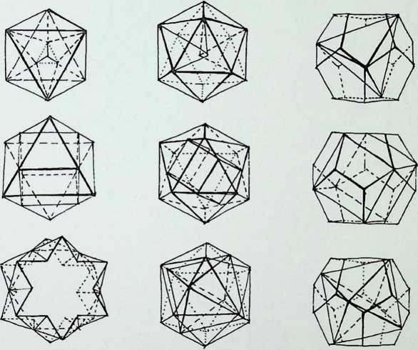
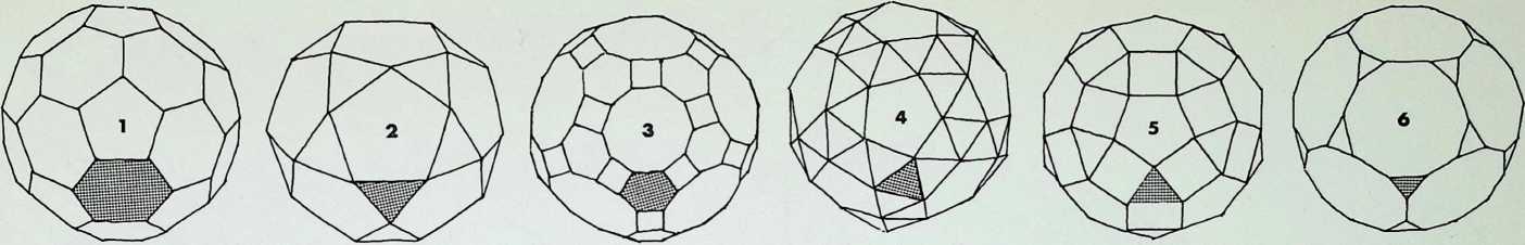
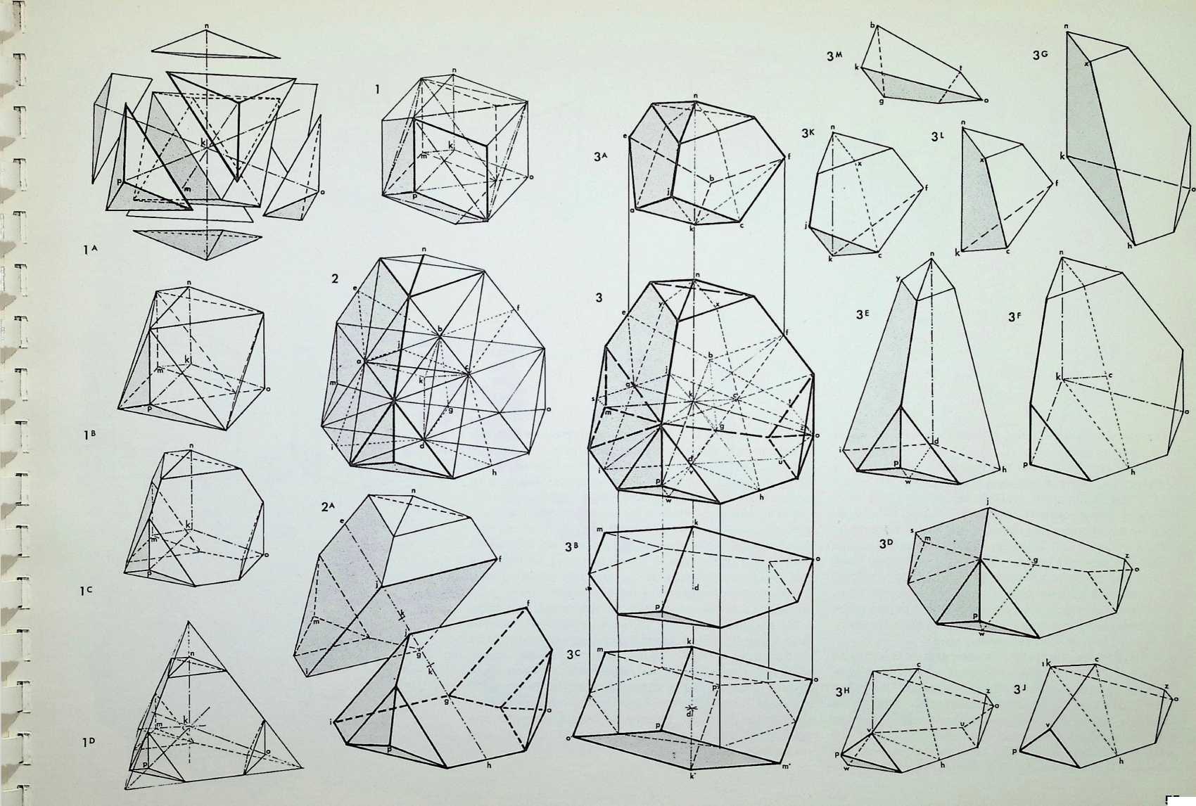
We have so far dealt with only two of the semi-regular solids, but there are thirteen possible semi-regular solids (pages 35 top. 37. 39 left). Each edge of a semi-regular solid is the same length and is characterized by the centre angle subtended by an edge at the centre of the enclosing sphere commonly denoted 0 (theta).
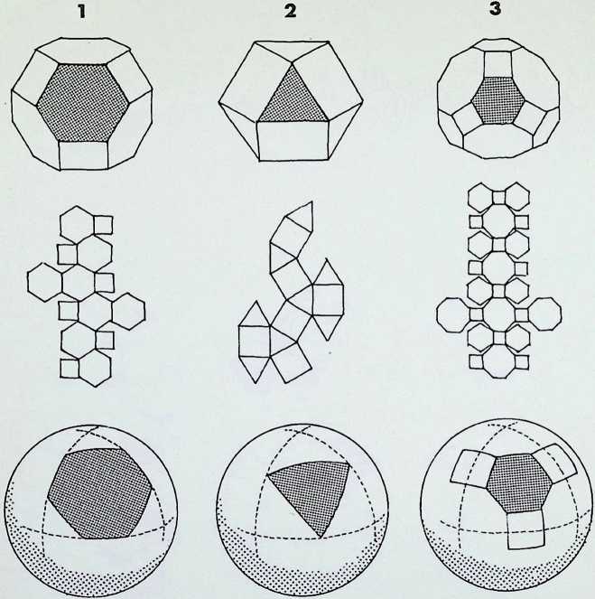
The group of drawings on the right shows the semiregular solids and their surfaces arranged in two parallel columns as successive truncations of the icosahedron, on the left. and. on the right, of the octahedron.
The surfaces or polygons indicated on the outer edges of the three rows of shapes are the same, they represent the amount of surface of the original solid left after truncation in each successive case. The column of surfaces shown vertically shaded are the new faces formed by truncation. The surfaces shown dotted are edge as opposed to corner truncations. Only in three instances (shown with a solid outline) does this result in an additional shape.
The arrangement is in order of hierarchy from most parent face to least after each successive truncation. An alternative arrangement would ensue if the cube and dodecahedron were taken as parent solids.
Archimedes work on the semi-regular solids has not survived, but one source. Heron, states that Archimedes ascribed the cuboctahedron to Plato. See Heath. A History of Greek Mathematics, p 295.
THE ARCHIMEDEAN OR SEMI-REGULAR SOLIDS ANALYSED BY NUMBER AND SHAPE OF FACES
THE GENERATION OF THE BASIC POLYGONS
Pattern of unfolding or degrees of order in space
THE POLYGONS OF
THE SEMI-REGULAR
SOLID FACES
THE NUCLEAR TRUNCATED TETRAHEDRON
snub dodecahedron
small rhombicosidodecahedron
truncated dodecahedron
I ‘ 1
. ALTERNATIVE
DODECAHEDRAL
i FACE I
; ; ;
[FACE NODE EDGE]
The triangle is the prime polygon and only structural shape, followed by the square, pentagon, hexagon, octagon, decagon and dodecagon. The broken lines indicate relationships of concord between the polygons
ICOSAHEDRON
OCTAHEDRON
RELATIONSHIP OF FACES TO PARENT SOLIDS

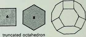
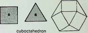
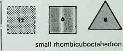
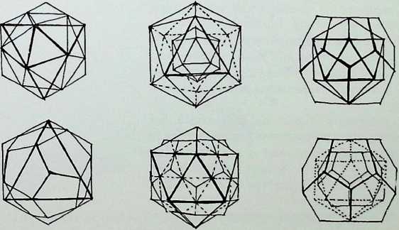
Six of the semi-regular solids of the octahedral family are shown here in three of their aspects:
divisions of the sphere surface. All lines are geodesic and great circles. The five regular solids are:
 **truncated octahedron**                             A   **tetrahedron**
 **cuboctahedron** or **dymaxion**                    B   **octahedron**
 **truncated cuboctahedron**                          C   **cube**
 **snub-cube** (which can be left- or right-handed)   D   **icosahedron**
 **rhombicuboctahedron** or **square-spin**           E   **dodecahedron**
 **truncated cube**
They are arranged in sequence from left to right as a series of increasing truncations of the parent octahedron. That is. each of the shaded faces shows a diminishing area of the face of the octahedron from which they were truncated.
The development or net of each of the figures is shown below it: below that is an exploded spherical projection of each solid (only one face, that corresponding to the shaded face in the top row of figures, being indicated).1
It may be further noted that the great circle lines on the tetrahedron. A, and cube. C. are the same as in each case they reciprocate diagonal lines of the others faces. Also the great circles of the icosahedron. D. and dodecahedron. E. are the same as they are duals. The octahedron, B, is divided into triangles similar in proportion to, but larger than, the icosahedral basic triangle.
In the bottom row are the full spherical symmetries of the five regular solids, showing that they are the regular
1 Euclid (xvin, 18) found all the circum radii of the containing spheres of the semi-regular solids.
E

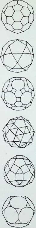
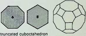
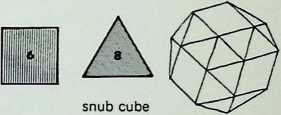
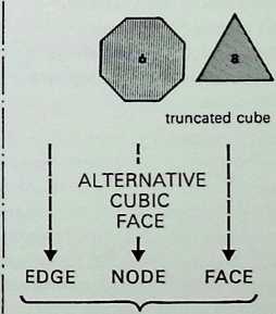
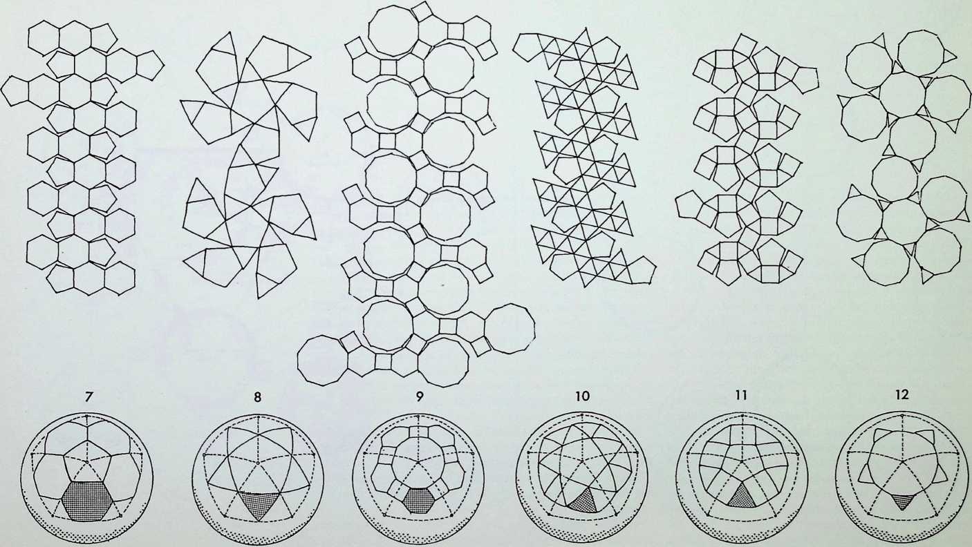
The six semi-regular solids of the icosahedral family, corresponding to those of the octahedral family on the previous page, are shown here in three of their aspects:
-
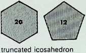
truncated icosahedron
-
icosidodecahedron
-
truncated icosidodecahedron
-
snub-dodecahedron
-
rhombicosidodecahedron
-
truncated dodecahedron
As before, these are arranged in sequence as a series of increasing truncations of the parent icosahedron.
The development or net of each of the figures is shown below it, with the spherical projection of the solids on to the circumscribing sphere in the bottom row (7, 8, 9, 10, 11. 12).
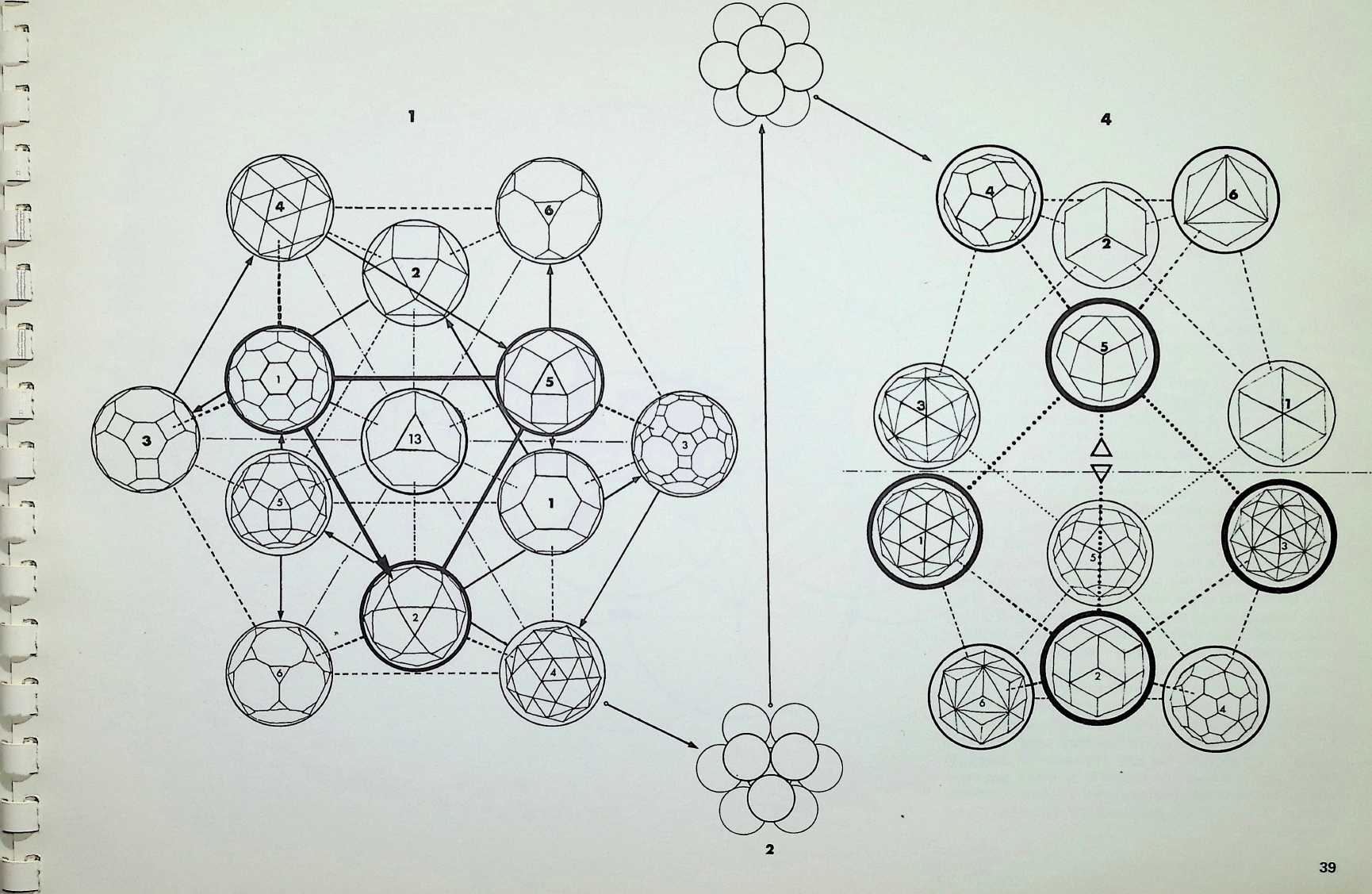
A single nuclear sphere totally surrounded by equal and similar spheres, as shown on pages 13 (in dotted outline in the centre drawing) and 27. has only twelve degrees of freedom for other spheres to touch it simultaneously. This arrangement of thirteen spheres in its most regular pattern is known as the cuboctahedron or dymaxion. On the two previous pages it has been shown that there are six truncations respectively of the regular octahedron and icosahedron. These twelve figures together with the one possible truncation of the regular tetrahedron give the thirteen finite Archimedean solids. The definition of an Archimedean or semi-regular solid requires that all its vertices lie in the surface of a circumscribing sphere. Thus the thirteen circumspheres of the Archimedean solids can be grouped in regular cuboctahedron or dymaxion pattern, that is the twelve spheres representing the possible truncations of the octahedron and icosahedron around the unique truncation of the tetrahedron (see appendix 4). This truncation of the tetrahedron has the apposite property of reflecting the twelve degrees of freedom in being the only semi-regular solid figure with twelve independent axes passing through its vertices from its centre. The arrangement of the twelve semi-regular solids around the truncated tetrahedron is in accord with the hierarchy established on the three preceding pages.
As with the Platonic or regular solids, there are duals to each of the Archimedean or semi-regular solids. The centre-point of each face of each of the Archimedean solids is the vertex of the dual. Each of the solids and its dual come into correspondence when the centre points of their respective edges (crossing at 90°) lie in the surface of a common sphere, known as the intersphere. The full numerical value of the inspheres, interspheres and circumspheres for these figures are given in appendix 1.
Figure 2 shows the twelve spheres close packed around an equal and similar nuclear sphere. Figure 3 shows the twelve spheres closed into icosahedral pattern after the removal of the nucleus.
In figure 4, the icosahedral grouping is shown expanded, each of the spheres containing the respective dual of the Archimedean solids represented in figure 1.
The six duals of the octahedral family are shown in the top half of the diagram, those of the icosahedral family in the bottom half.
In this configuration the two families of symmetry separate out into an above and below reflection of six.
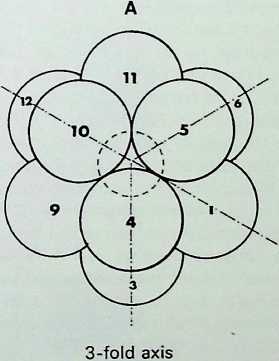
These drawings show the change from a cuboctahedral pattern (twelve spheres around an equal and similar nucleus) to an icosahedral pattern (twelve spheres without an equal nuclear sphere). The variation in size of possible nuclear spheres is shown in the middle drawing, with the maximum size lightly shaded and the minimum darkly shaded.
The cuboctahedron or dymaxion in figure A, with its points numbered 1. is viewed centrally in its 3-fold axis.
The central figure, B. still viewed in a 3-fold axis, shows the change to the icosahedron. The position of points 1. 2 and 3 (and the corresponding 10. 11 and 12. which are not shown) does not change in this view; but the position of points 4. 5. 6. 7, 8 and 9 does change, and each of these is shown in two positions, smaller numbers being used for the first, larger ones for the final position. Of the eight triangular faces of the initial figure, the two directly central, above and below, remain in the same rotational position, although they close in towards each other; the remaining six triangles, three above the meridian and three below, rotate to close in. A tone has been put on the three upper triangles to show the nature of this rotation, in both positions, with arrows following the direction of movement. In this way it is possible to see how the square faces close across their diagonals (this path has been indicated with arrows on the drawing on page 39) to create two equilateral triangles for each original square. The final icosahedral position. C. is structurally stable as it is a totally triangulated configuration.
B


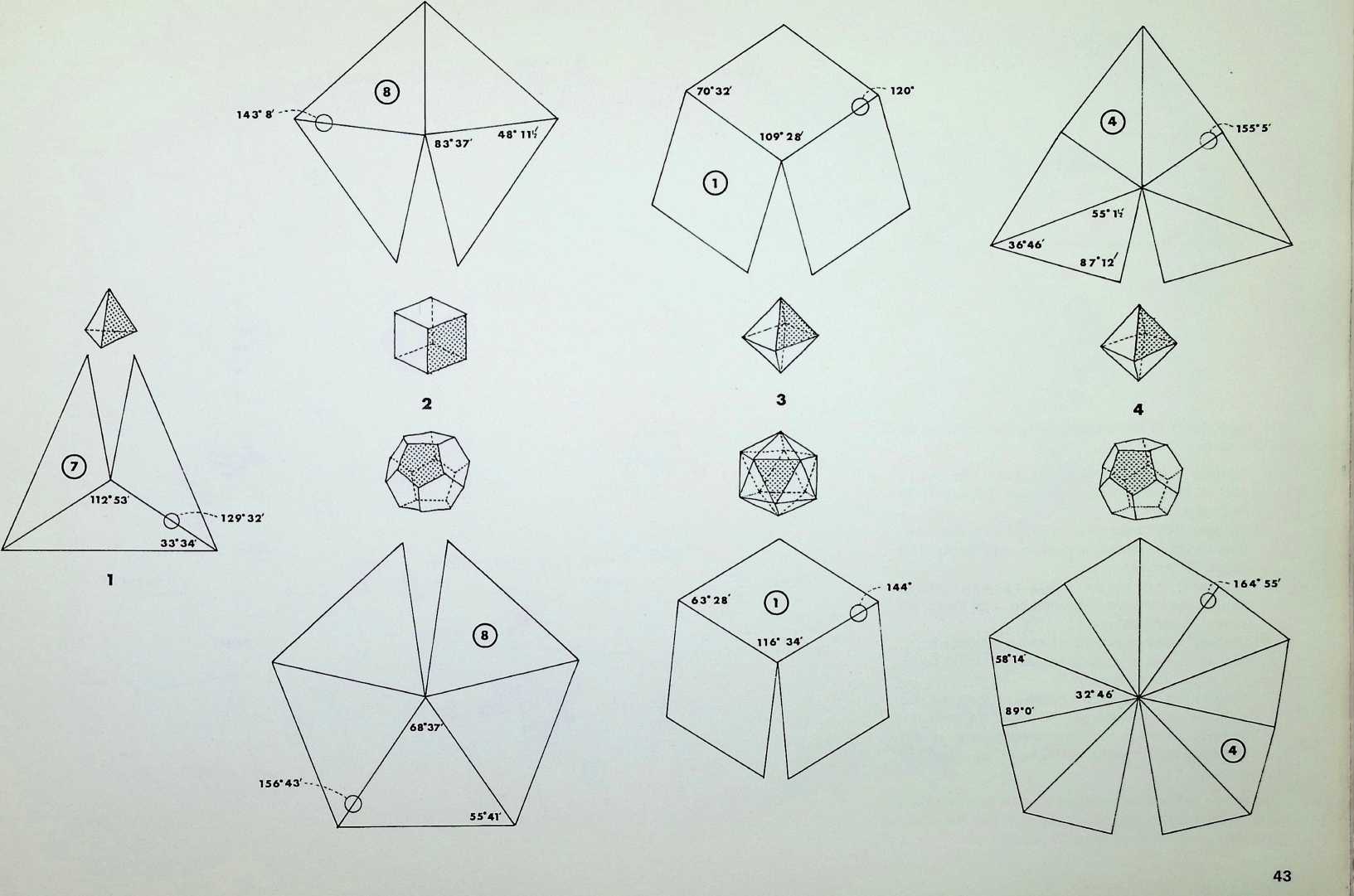
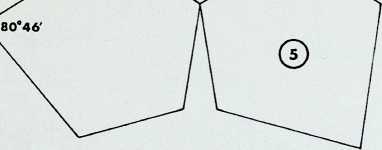
The components of seven of the Archimedean duals are shown here:
-
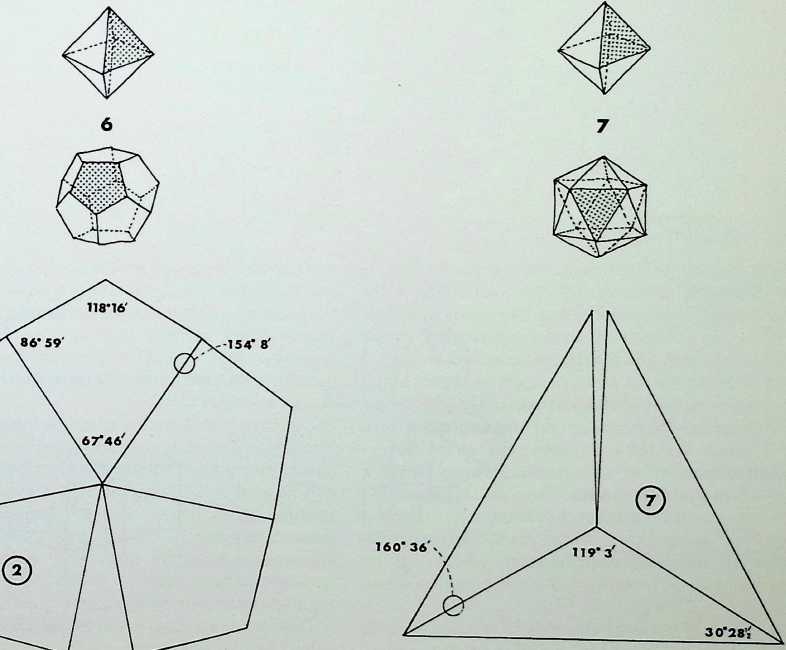
[triakis tetrahedron,]{.smallcaps} dual of the truncated tetrahedron faces, 18 edges, 8 vertices
-
(above) [tetrakis hexahedron,]{.smallcaps} dual of the truncated octahedron faces. 36 edges, 14 vertices
-
(below) [pentakis dodecahedron,]{.smallcaps} dual of the truncated icosahedron - 60 faces. 90 edges. 32 vertices
-
(above) [rhombic dodecahedron,]{.smallcaps} dual of the dymaxion faces, 24 edges. 14 vertices
-
(below) RHOMBIC TRIACONTAHEDRON, dual of the icosidodecahedron faces. 60 edges, 32 vertices
-
(above) [hexakis octahedron,]{.smallcaps} dual of the truncated dymaxion faces, 72 edges. 26 vertices
4 (below) [hexakis icosahedron,]{.smallcaps} dual of the truncated icosidodecahedron - 120 faces, 180 edges, 62 vertices.
The developments of each characteristic group of faces of these duals is shown in relation to the regular figure on which, if placed, it would make up the whole.
The face angles are noted as are the dihedral angles, i.e. the angles between adjacent faces, which are marked by small circles lying across the two faces.
The circled numbers in each face refer to the value analogous to the duals of the two-dimensional spacefilling lattices developed on page 77.


The components of the six remaining Archimedean duals are shown here:
- (above) [pentagonal icositetrahedron.]{.smallcaps} dual of the snub-cube faces, 60 edges, 38 vertices
-
(below) PENTAGONAL H EX A C O N T A H E D R O N , dual of the snub-dodecahedron - 60 faces, 150 edges, 92 vertices
-
(above) [trapezoidal icositetrahedron.]{.smallcaps} dual of the rhombicuboctahedron faces, 48 edges. 26 vertices
- (below) TRAPEZOIDAL H EX A C O N T A H E D R O N . dual of the rhombicosidodecahedron - 60 faces.
1 20 edges, 62 vertices
- (above) [triakis octahedron,]{.smallcaps} dual of the truncated cube faces, 36 edges, 14 vertices
- (below) [triakis icosahedron,]{.smallcaps} dual of the truncated dodecahedron faces. 90 edges. 32 vertices.
As before, the circled numbers in each face refer to the value analogous to the duals of the two-dimensional space-filling lattices developed on page 77.
153* ir
118 8
.67’28


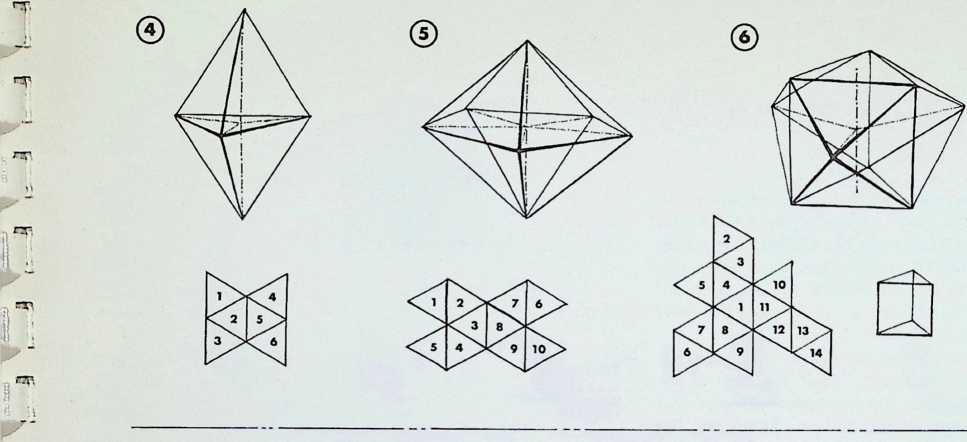
This page is divided into two sections, the top half being diagrams displaying properties of the five of the eight deltahedra having faces composed of equilateral triangles. The first three (not shown here) are the regular tetrahedron, the regular octahedron and the regular icosahedron.
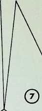
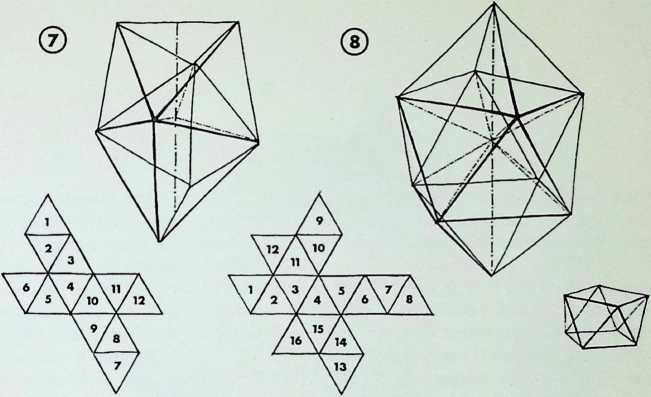
Drawing 4 shows the net and a perspective sketch of the twin-tetrahedron or hexadeltahedron. Drawing 5 shows the twin-icosacap deltahedron or decadeltahedron. Drawing 6 shows the net and perspective of the tetra- kaidecadeltahedra or, as the smaller drawing below it shows, the trigonaldeltahedra. Drawing 7 shows the net and perspective of the dodecadeltahedra, and drawing 8 the net and perspective of the cubicantiprismic- deltahedra or hexadecadeltahedron, which can be viewed as two half-octahedra on a cubic antiprism (seen below it).
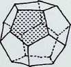
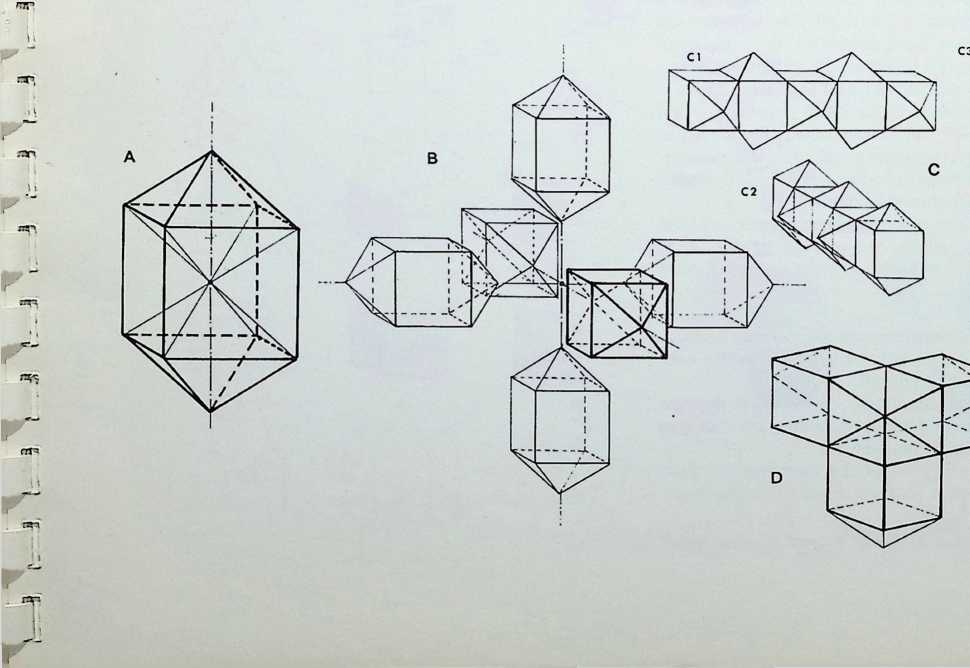
The lower halt of the page shows a further version of a single all-space-filling polyhedra which is late to emerge and can be considered a transition phase between the cube and the rhombic dodecahedron. It has particularly interesting properties and has therefore been explored separately. This also is a pristine solid as it cannot be otherwise in proportion but is less symmetrical than the snub-tetrahedron. It has been named the pencil cube (dodecahedron) due to its shape.
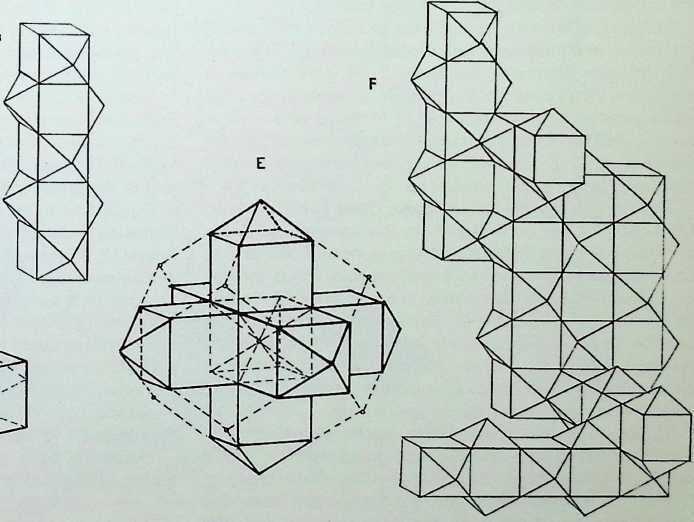
Drawing A shows how it can be viewed in terms of unfolding cube or as four space-filling octahedra. Drawing B demonstrates the 6-fold nature of its packing function. This can be analysed © as the x, y, z axes and can be fitted together as in C1. C2 and C3. Drawing D shows how three fit together forming a cube corner or half a three- dimensional cross. In drawing E we see the full three- dimensional cross assembled with broken lines demonstrating the relationship to the rhombic dodecahedron.
Drawing F explores some of the close-packing patterns expected with this figure.

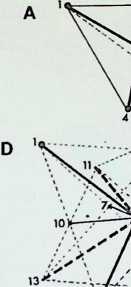
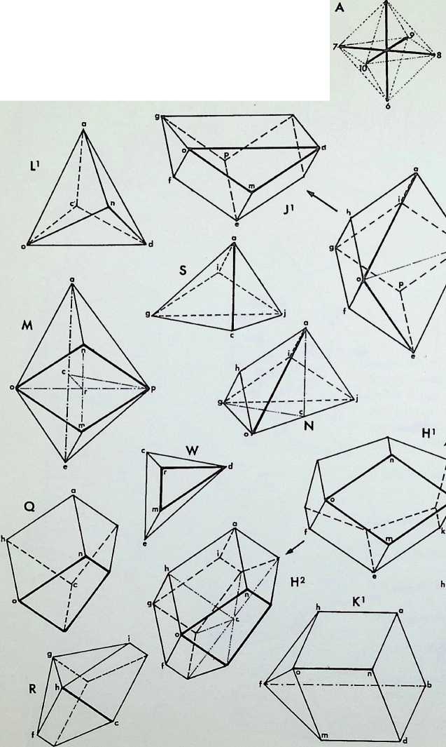
The figure A at the top of the page is a tetrahedron on its edge; with its four central axes in heavy line. These axes, numbered 1, go from the centre of the figure to the four nodes.
Figure B shows the X. Y. Z axes, which are the axes of the centres of the opposite pairs of edges of the tetrahedron; these have here been unfolded from the centre to give three interpenetrating squares (in dotted outline).
Figure C shows the diagonals AA, BB, CC, DD, of a cube, which can also be considered as the axes of two interpenetrating tetrahedra. These have been unfolded, as for B. to give a series of rhombs twelve in all - describing the rhombic dodecahedron (in dotted outline).
In figure D the two sets of axes described in B and C are shown in equilibrium, with a common centre. There are thus fourteen directions, numbered 1. This number of directions corresponds to the number of facets in the ideal close-packing solid ideal that is in terms of minimum surface area to maximum interior volume. Even in random packing, as J. D. Bernal has pointed out.1 the average number of faces is 13-7. which can be considered as 14.
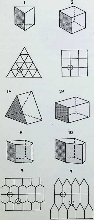
Figures 1-8 are the basic simple close-packing solids. Of these 1 are generated from the square; the snubtetrahedron. 4. and the master solid or truncated octahedron. 5. are adaptations of the two primary regular solids and can be related to the fourteen axes in D above them. These two solids have unique qualities: the snub-tetrahedron being pristine, i.e. it cannot be distorted on any of its axes and remain a single close-packer; and the truncated octahedron being the most economic close-packer, hence the master solid’ among the close-packing unit figures.
Figures 6-8 are dodecahedra. each related to C in their rhombic faces the rhombic dodecahedron, 6. has twelve rhombic faces; the twist rhombic dodecahedron, 7. has six rhombic faces and six trapezoidal faces; the rhombhex dodecahedron. 8. has eight rhombic and four hexagonal faces.
The drawings immediately below the line of solids 1-8 show the corresponding close-packing grids. 1A, 2A and 3A show extensions on a particular axis of the three primary prisms 1. 2. 3. 1A and 3A indicate the most economic condition of surface to interior volume (for formulae for volume see appendix 1), 2A moves away from the most economic condition of the cube 2.
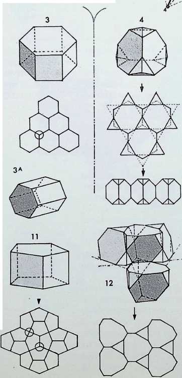
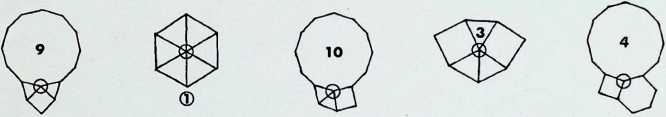
Figures 9. 10 and 11 show pentagonal close-packing prisms, with an order of symmetry lower than that of the three regular prisms. Each of the pentagons contains two right angles on its characteristic surface. Below are the packing grids for these solids. It should be noted that the packing grids of the regular prisms are in themselves totally regular, each intersection is the same. The packing grids of the pentagonal prisms have three- and four-way intersections, indicated by circles, and are hence less regular.
Figure 12 can be seen to be an orthic projection of the snub-tetrahedron, which can be assembled in two parts to result in a version of an intersecting twist rhombic dodecahedron, 15 (see also page 57, drawing 1E). The medial grid of the projection is shown below it.
Figure 1 3 can be seen to be an orthic projection of the truncated octahedron, which can also be halved, as in figure 12. The medial grid below is made up of octagons and squares and qualifies as one of the eight semi-regular patterns on a surface.
Figure 14 shows an adaptation of the rhombic dodecahedron which could be analysed as a dymaxion with a halfoctahedron added top and bottom.
Figure 15 shows an adaptation of the twist rhombic dodecahedron. Trapezoidal faces have become triangles (see page 57 for the transformations).
Figure 16 is an adaptation of the rhombhex dodecahedron. The packing grids of these solids are below them.
1 J. D. Bernal, The Structure of Liquids, Scientific American. August 1960.
Page 49 laid out a method of viewing the single all-spacefilling polyhedra in a periodicity of eight. This arranged itself into a three-two-three pattern with the pristine snubtetrahedron and the truncated octahedron (or master solid) making up the central pair (the arrangement, however, is not exclusive). This page shows transformations of the truncated octahedron. These have been shown in six representative stages. The whole movement is generated by turning the diagonal axes of two of the square faces of each truncated octahedron (ringed and arrowed in the central diagram): these point directly towards the eye. The central drawing shows stages one and six overlaid with these separated out in the smaller drawings above and below the centre. The axes of rotation are arrowed in each case.
In drawing 1 we have four close-packed truncated octahedra, two nearer the eye and two behind; the uppermost of the nearer pair is outlined by the numbers 1 to 8 on each corner. Corner 2 and axis A are together as are corner 7 and axis D. The four axes marked with arrows turn left- handedly in A and C and right-handedly in B and C.
The movement through 22^° produces a series of enantiomorphic bifurcations (2. 3. 4, 5) until the two upper truncated octahedra merge to become one large demi-regular version of the master solid. The last figure (efghijkl) has six square faces and eight hexagonal, but two of the squares are larger and the hexagons are not regular, also the new figure has not 3-fold symmetry, 6.
Drawing 2 shows the first stages where the upper pair of solids move towards each other and the lower pair away from the upper pair. This could be named a new single close packer as it is made up of trapezoids, squares and irregular hexagons. The name traphexahedron is suggested.
Drawing 3 shows how the trapezoidal faces extend to meet at the central face and in doing so produce a transformation from a fourteen- to a thirteen-faced solid, now made up of squares, trapezoids and irregular pentagons. The name trapentahedron is suggested.
Drawing 4 represents a further phase in the transformation where the trapezoids now become another form of irregular pentagon and the major interface between two solids becomes an irregular hexagon. This figure was discovered by D.G. Wood via one of the pentagonal space-filling prisms and he has suggested the name triskaidecahedron.
Drawing 5 shows the transformation when the interface between the enantiomorphic solids becomes an equal-edged hexagon (central seam). This is also a thirteen-faced solid, and due to its near transformation back into a tetrakaidecahedron is shorter and more stubby than its neighbour triskaidecahedron; therefore the name snubtriskaidecahedron is suggested in order to distinguish it.
This brings us full-circle back to drawing 6 which shows that the two enantiomorphic figures when the pentagonal faces line up become hexagons and squares respectively of a newly proportioned fourteen-faced solid made up of squares and hexagons in the same way as in its generating figure, the truncated octahedron. This new figure might be called the polar tetrakaidecahedron due to its two polar square faces being nearly twice the size of its remaining four equatorial square faces.
The whole page summarizes the demonstration that there may well be indefinite numbers of transformations of the basic single space-filling solids, but that there is a good case to put forward an eightfold periodicity, following the example of the random all-space-filling deltahedra which are governed by a factor of eight possibilities only. These are the eight equilaterally faced convex deltahedra (see appendix 2).
rp


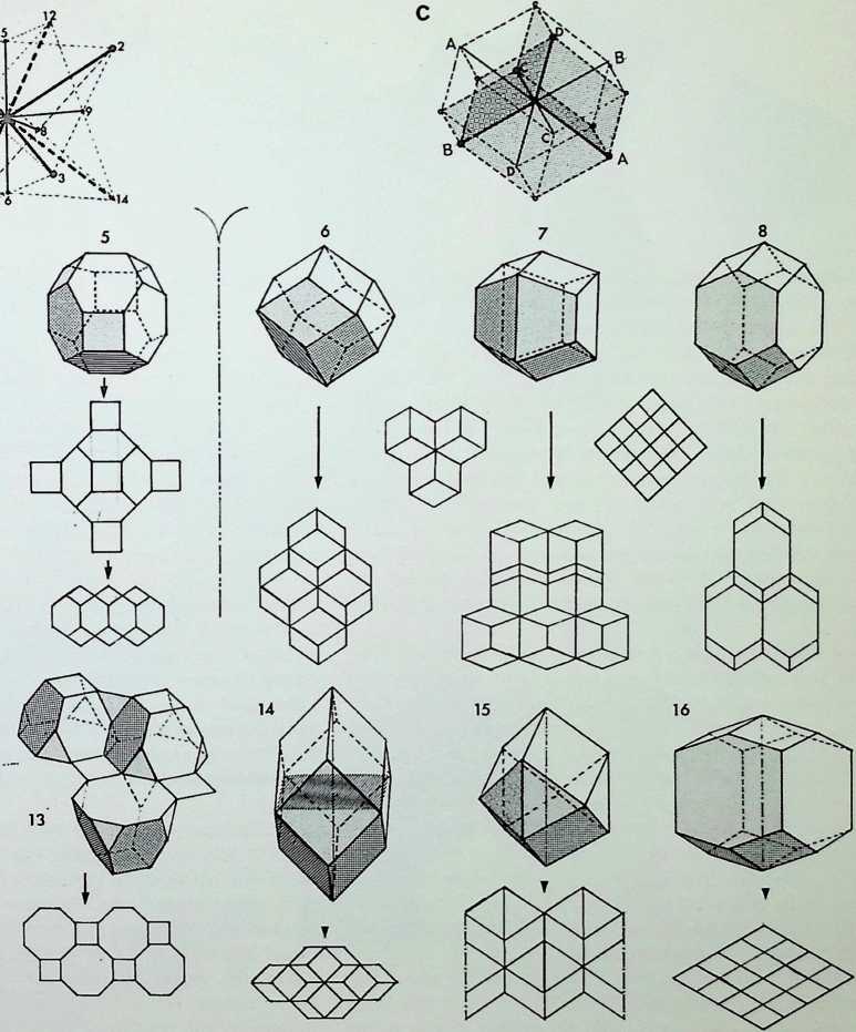
This page further demonstrates the subdivisible possibilities of one of the key all-space-filling solids the rhombic dodecahedron. At the top of the page drawings A and B the x, y. z, and a. b, c. d axes are numbered 1. Drawing C demonstrates how these two when put together can be viewed as the octahedron and cube interpenetrating. When all the points are joined in dashed line the rhombic dodecahedron emerges.
Drawing D at the centre of the page has certain central axes drawn through it (ae, oj, sq, gd, tr) which indicate axes for bifurcation. All the decomposite parts of the central figure are single all-space fillers, although in some cases enantiomorphic.
Drawing E shows the significant tetra- and octahedra which are single all-space fillers as in opposition to their regular counterparts which are only complementary allspace fillers. This diagram also demonstrates that the volume of the tetrahedron is % that of the octahedron.
A brief description of the remaining drawings follows:
F1 and F2 are two views of J rhombic dodecahedra with a hexagonal section:
G1 and G2 are further versions of half rhombic dodecahedra:
H1 and H2 are another possible bifurcation of the rhombic dodecahedra;
J1 and J2 are longitudinal bifurcations of the rhombic dodecahedra with a square section;
K’ and K2 are two views of J rhombic dodecahedra;
L1 and L2 are Fullers hexahedra, all-space-filling deltahedra made up of a J regular tetrahedron and a regular octahedron;
M is a J rhombic dodecahedron as is drawing N and the two views of O and O2;
P is yet another version of a i rhombic dodecahedron;
Q is of a rhombic dodecahedron being of the half H1;
R is another version of a £ rhombic dodecahedron;
S is a rhombic dodecahedron being drawing N;
T is also a rhombic dodecahedron being J drawing P;
U is -g- as it halves drawings O and O2;
V is J-2 of the rhombic dodecahedron being a solid version to the centre angle of each of its twelve faces;
W is Jg being £ of the drawing M :
X represented another type of tetrahedron being half the first mentioned - this tetrahedron needs to be enantiomorphic to be an all-space filler.
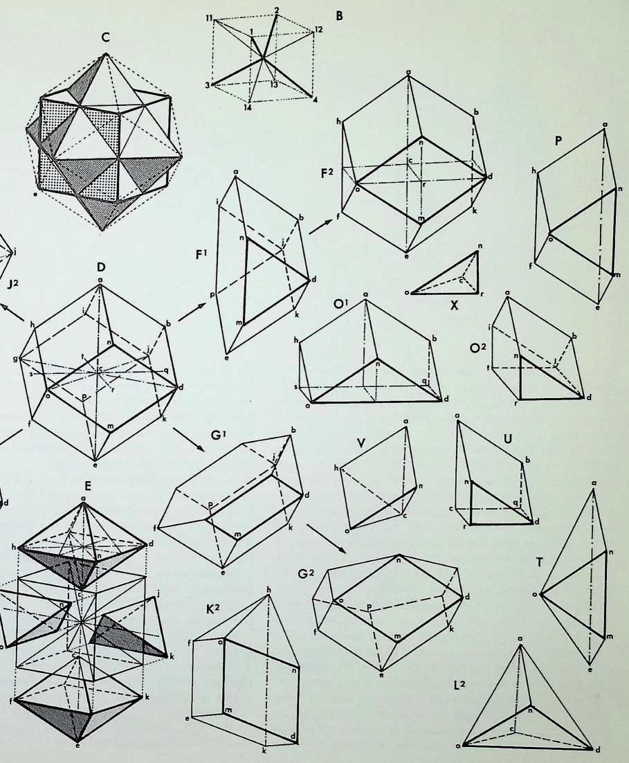
This page divides into three figures. The first, drawing 1. is the rhombic dodecahedron with the longer axes of each rhombic face dashed. This demonstrates the nature of the rhombic dodecahedron as being made up of one octahedron with eight % regular tetrahedra, as shown exploded in drawing 1A. From here it is possible to demonstrate the relationship of this construction to the pristine snubtetrahedron. If one takes away four of the i regular tetrahedra from the octahedron one is left with a figure as shown in 1 B. This is not in itself a single space filler. These can be demonstrated in the transformation, 1C, which shows that the octahedron face has to grow to become a hexagon. When this becomes regular, 1 D. then the pristine snubtetrahedron is arrived at. Only with equated edges of the hexagon is single close packing possible.
Drawing 2 shows an analysis of the snub-tetrahedron, a figure discovered by the author, in terms of subdivisions of regular octahedra and tetrahedra. Each component face of the octahedra is shown to have one outer % tetrahedron to make up the snub. Drawing 2A shows a method of bifurcation into a less regular all-space-filling polyhedron.
Drawing 3 shows the snub-tetrahedron with its basic axes of subdivision: 3A. 3B. 3C are taken directly out of the parent figure. The upper enneahedron is made up of three pentagons, three trapezoids and three triangles. The lower heptahedron, 3B. shows itself to be a quarter of the snubtetrahedron as with the enneahedron. The heptahedron has the interesting quality of being half the all-space filling 109° 28 hexahedron. 3C. The following names are suggested for these significant components of the snubtetrahedron: .the all-space-filling enneahedron, heptahedron and rhombic hexahedron.
Drawing 3D shows another method of bifurcation and is enantiomorphic as a single space filler.
Drawing 3E is a snub-tetrahedron.
Drawing 3F is another view of the heptahedron. with sectional axes added.
Drawing 3G is a snub-tetrahedron bifurcating the heptahedron.
Drawing 3H is a snub-tetrahedron and 3J halves this and is therefore a snub-tetrahedron.
Drawing 3K is a enneahedra. Therefore also a snubtetrahedron.
Drawing 3L is a bifurcation of 3K. therefore of the snubtetrahedron but enantiomorphic.
Drawing 3M is an ultimate particle of the snub-tetrahedron and is another view of 3L, the part of the snubtetrahedron.
All these decompositions of the parent figure can be regarded as all-space-filling solids.
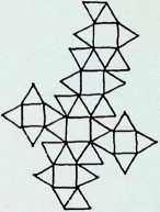
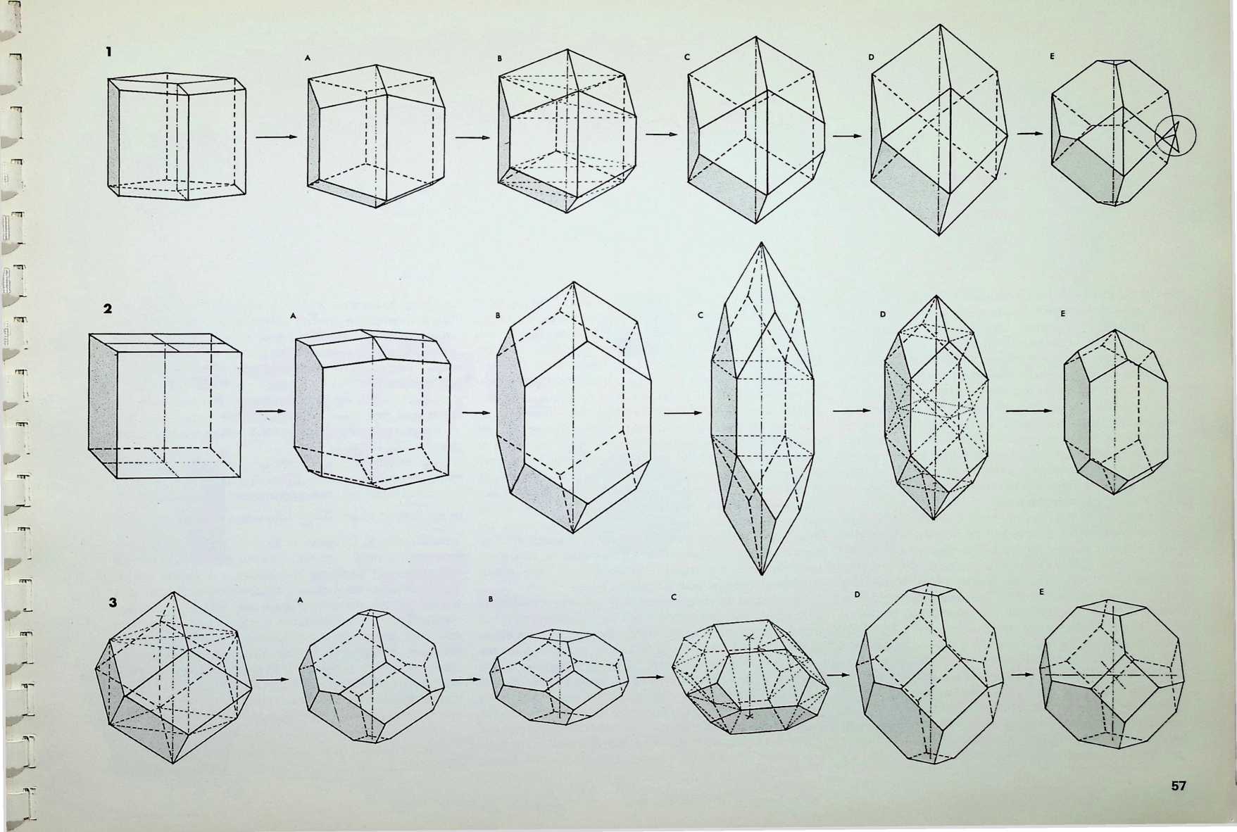
This page shows three series of transformations of single close-packing solids.
The top row starts with the hexagonal prism with its hexagonal face divided three ways, 1; 1A shows the beginning of a transformation towards 1B, which is the twist rhombic dodecahedron. The lighter dotted lines indicate an intrinsic pair of triangular prisms. In 1C a further transformation on the same axis is shown, and in 1 D the trapezoidal faces have become triangular; 1 E shows the ultimate result of a further series of transformations from 1 D, when the top three and bottom three rhombs are made to interpenetrate by contraction on the same axis. Only one of the interpenetrations, that ringed, shows the surfaces complete, where they have moved beyond the solid.
The middle row starts with the cube with its face divided four ways. 2; 2A shows an extension on the central axis, resulting in 2B, which is the equal-edged rhombhex dodecahedron. In 2C we see further transformation on the same axis, where the hexagon face has become a square plus two equilateral triangles, giving a cubic core to the solid. Keeping the same cubic core, the longitudinal axis can be reduced to result in 2D. which has 120° and 60° rhombs. The figure is made up of two dymaxions plus two half-octahedra, top and bottom, with four tetrahedra to complete the figure around the middle (dashed lines). Finally 2E retains the cubic core, but reduces the longitudinal axis further so that the angles of the hexagonal face are 120°.
The bottom row starts with the rhombic dodecahedron, 3, with its cubic core shown in dashed line. In 3A the four rhombic faces which meet at the top and the four which meet at the bottom apices have contracted on the polar axis and interpenetrated at the meridian, resulting in a complementary truncation of the two apices. Drawing 3B represents a further contraction on the vertical axis to an orthic equilibrium, and 3C shows a similar figure, viewed rotated slightly, to indicate that all hexagonal faces can be controlled by a regular square from two parallel edges, shown in dashed line. The relationship between these squares is determined by equilateral triangles. Drawing 3D shows an extension of the figure on the vertical axis until all the rhombic faces become squares. Contracted into equilibrium, this provides the master solid, the truncated octahedron. 3E.
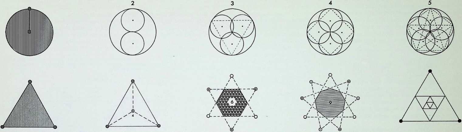
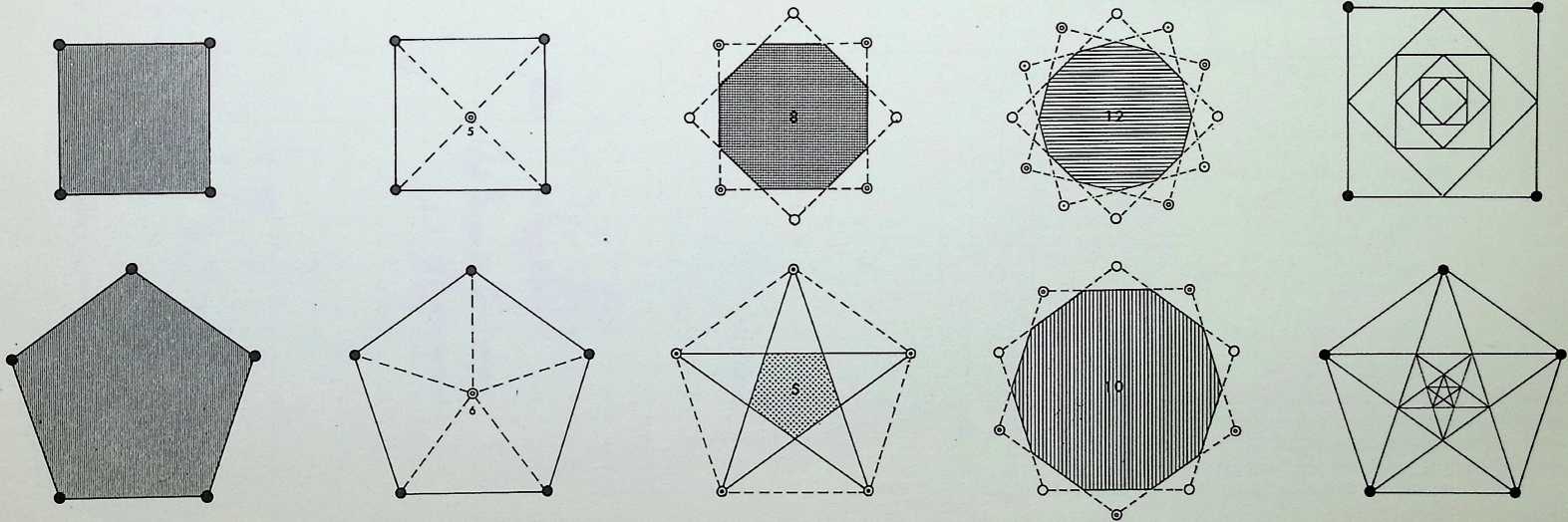
We return now from a consideration of solids defined by points in space to those shapes made up by the surface areas between the points. Very few basic shapes are required to order all the regular shapes.
The diagrams in the first column show, successively, the number of points required to determine the first four basic shapes two, the centre and the periphery, determine the circle, three the triangle, four the square, five the pentagon. The triangle, the square and the pentagon are related directly to the first three Platonic solids - the tetrahedron is a three-based pyramid, the octahedron can be viewed as three squares intersecting, while the pentagonal arrangement of points is the characteristic (with its Golden Mean properties) of the icosahedron.
The diagram at the top of column 2 shows, firstly, how two subsidiary circles, exactly half the radius of the greater, can fit within it and not intersect. This diagram is the basis of one of the oldest of Oriental symbols, the universal principle of Yin and Yang, the greater circle representing the Tao or way of the universe. The remaining diagrams in column 2 show that each of the other basic shapes or polygons has its controlling centre-point.
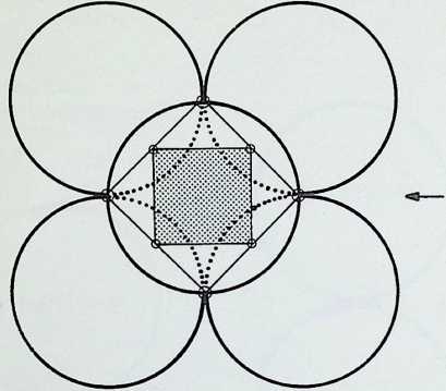
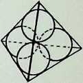
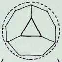
The diagram at the top of column 3 shows three circles, each half the radius of the greater circle, placed regularly within it. The lines joining the points of contact between the greater circle and the inner ones pass also through one of their points of intersection, delineating an inverted triangle exactly one-quarter the area of the triangle circumscribing the greater circle. A similar, but square, patterning occurs (column 4) when four subsidiary circles are introduced into the greater circle (also bisecting the sides of the square at their points of intersection), while five subsidiary circles (column 5) give the pentacle or 5-pointed star. In this instance a third point of intersection coincides with the centre-point of the cross-strokes of the pentacle 5.
The second diagram in column 3 shows the development of the hexagon or 6-sided polygon by overlapping two similar triangles the hexagon being their common area. The diagram below it shows the octagon resulting from the overlapping of two identical squares, while the result of joining all points of the pentagon, providing an inverted pentagon, is shown at the foot of the column. To the right, at the foot of column 4, is the decagon, 10, the figure resulting from the regular overlapping of two similar pentagons. Above this is the 12-sided configuration, the dodecagon, resulting from the regular overlapping of three similar squares. Above this is the nonagon or enneagon, resulting from the regular overlapping of three similar equilateral triangles with a common centre.
The second drawing in column 5 indicates a method of diminishing triangles successively by inscribing them one within another, each touching the centre-point of the edges of the previous one. This is known in architecture as the root three proportional system, particularly favoured by the builders of the Gothic cathedrals since it has obvious symbolic links with the concept of the Holy Trinity. The proportional system is generated by the tetrahedron in the solid, i.e. the proportion of the insphere to the circumsphere.
The third diagram in column 5 shows a similar diminishing pattern of harmonic squares, each successive square touching the centre-points of the edges of the previous one. The arrangement is known, architecturally, as the root two proportional system, the edges of successive squares diminishing by the square root proportion of the previous edge. The system was employed both by the architects of the Renaissance and by Chinese and Japanese Buddhist architects, the octagon being linked symbolically by the latter with the noble 8-fold path. The proportional ratio of an edge to a diagonal axis of the octahedron is also root two.
The bottom diagram in column 5 shows pentagons diminishing harmonically by linking up points of intersection of pentacles. The proportionate series that emerges x/5 + 1
is the Golden Mean, . In whole integers, this gives
us the harmonic progression 1, 1, 2, 3, 5, 8, 1 3, 21 …in which the sum of any two successive integers gives that following; conversely the subtraction of a smaller integer from that following it gives that preceding it. The series is known by the name of Fibonacci, that of the Italian mathematician who introduced it into Europe. The system has been noted in the architectural monuments of most historical civilizations. It has also been evidenced in botanical growth patterns.1 It is to be associated directly with the icosahedron, which can be considered as fifteen intersecting Golden Mean rectangles - that is a rectangle with adjacent sides in the proportion 1:1-6181.
1 DArcy Thompson. On Growth and Form: Lang. The Language of Mathematics.
Space-filling surface patterns
These have been called mosaics, tiles, grids, lattices and tessellations. They can be viewed as vertices or point conditions, lines or reticulations of the surface, or as the fitting together of regular shapes to fill a surface.
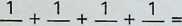
To cover a surface with regular shapes or polygons, leaving no spaces between the meeting-points of their vertices, if we take n as the number of sides each regular polygon will have, then the interior angles at each vertex of each polygon will be °. At each vertex there will be
n
360
7 - [2/7]{.underline} -0 4- [4]{.underline}
- -180 n - 2 n - 2
n
per vertex. In addition A, B, C, D, E and J can be eliminated as they can occur at only one point and will not provide a continuous pattern covering a whole surface. Thus there remain only eight conditions of meeting, which, it will be seen, give rise to twenty-two new patterns or grids. These can be divided by symmetry into those whose vertices are similar on each occasion and those whose vertices vary. There are eight semi-regular equipartitions of the plane surface and fourteen demi-regular equipartitions (see pages 79-83).
The eight combinations that give rise to the eight semi- and fourteen demi-regular equipartitions are given in table 2 in their new order as established in appendix 2. Seven of these eight combinations are employed in our definition
of the eight semi-regular partition numbers. The third and sixth are both arrangements of Q (marked Q1 and Q2 in the drawing): L qualifies only for the demi-regular patterns.
The fourteen demi-regular patterns can be classified as shown in table 3. Only thefifth of these patterns incorporates three vertex situations; four others (numbers 3. 8.11 and 1 2 in the table) together use three types of vertex, doubling on the combination of one of these. The remaining nine demi-regular patterns show the characteristics of using two vertex situations, and two of these (numbers 6 and 1 3) double on the combination of M and N respectively.
1 I am indebted to Professor Maurice Kraitchik for the basis of the mathematical formulae; see Mathematical Recreations (London. George Allen & Unwin. 1966).
such polygons. In order that this be a whole number for n greater than 2. n must have values equal to 3. 4 or 6. the regular shapes for figures with this number of sides being the equilateral triangle (1), the square (3) and the hexagon (2). These three are the only regular polygons that cover a plane surface, and are known as the regular equipartitions of the plane surface.
Earlier deductions have shown that there cannot be less than three polygons nor more than six around a vertex. The range of three to six polygons surrounding a vertex provides the equation
[pi ~2]
n2 - 2
n2
n3 - 2
n3
180° = 360°,
*n~y~* ***^n^2*** ***^n^3*** ***^n^4*** ***^n^3***
A •K
B L
C M
D N
E •P
F Q2
G R
H •s
J
Table 1
New number Code letter 7?1 n2 Faces n3 n4 "a
M
N
Q
G
R
E
H
L
Table 2
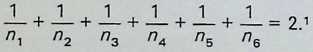
which gives us
±+±+J_=l.
n2
Following the same procedure, we can also say
/?2 ^3
and
and finally
± + ± + ± + ± + ±=3
^2 ^3 ^4 ^5 2
From this it follows that there are seventeen possible solutions in whole numbers, shown in table 1. Of these, the three marked with an asterisk (K, P and S) can be discounted as they were the first and only totally regular solutions, i.e. three hexagons, four squares and six triangles
                                          ***^n^3***   A.         ***^n^2***   ***^n^3***   A,   ***^n^s***   °6
 E+L
 L+(1)
 L+Q’
 N+G
 L+Q +(1)
 M + M’
 N+Q
 N + Q^2^+Q
 Q’+(1)
 Q’+(1)
 Q^2^ + Q^1^ + (1)
 Q^2^+Q + (1)
 N+N
 N + Q^2^
Table 3 • (t) = regular equipartition.
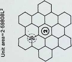
AREAS OF EACH SHAPE ARE INDICATED IN NUMERALS BASED ON UNIT EDGE LENGTH (L)
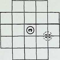
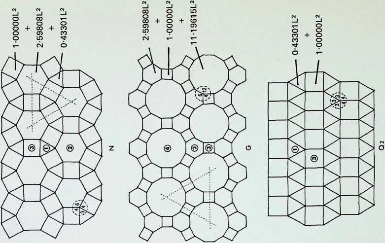
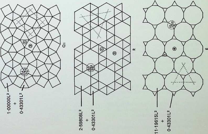
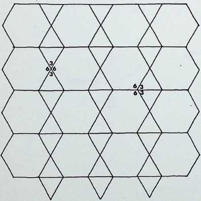
The first five of the fourteen demi-regular patterns are shown here with the nodal condition enumerated in figures; the ringed numbers in the centre of the polygons represent the analogy value to one of the eight semi-regular patterns.
Diagram 1 can be expressed as E + L. with nodal conditions 3, 12, 12; and 3, 4, 3. 1 2 analogous to pattern 8 of the semi-regular patterns.
Diagram 2 = L + (1). with nodal conditions 3, 3. 4, 12; and 3, 3, 3, 3, 3, 3 analogous to pattern 4 of the semiregular patterns.
Diagram 3 = L + Q’_ with nodal conditions 3. 4, 3. 12;
- 3, 4, 12; and 3, 4, 3, 3, 4 analogous to pattern 5.
Diagram 4 = N + G, with nodal conditions 6, 4, 3, 4; and 12, 6, 4 - analogous to pattern 4.
Diagram 5 = L + Q1 + (1). with nodal conditions 3, 3.
- 12; 3, 4, 3. 3, 4 and 3. 3, 3. 3, 3. 3.

J;
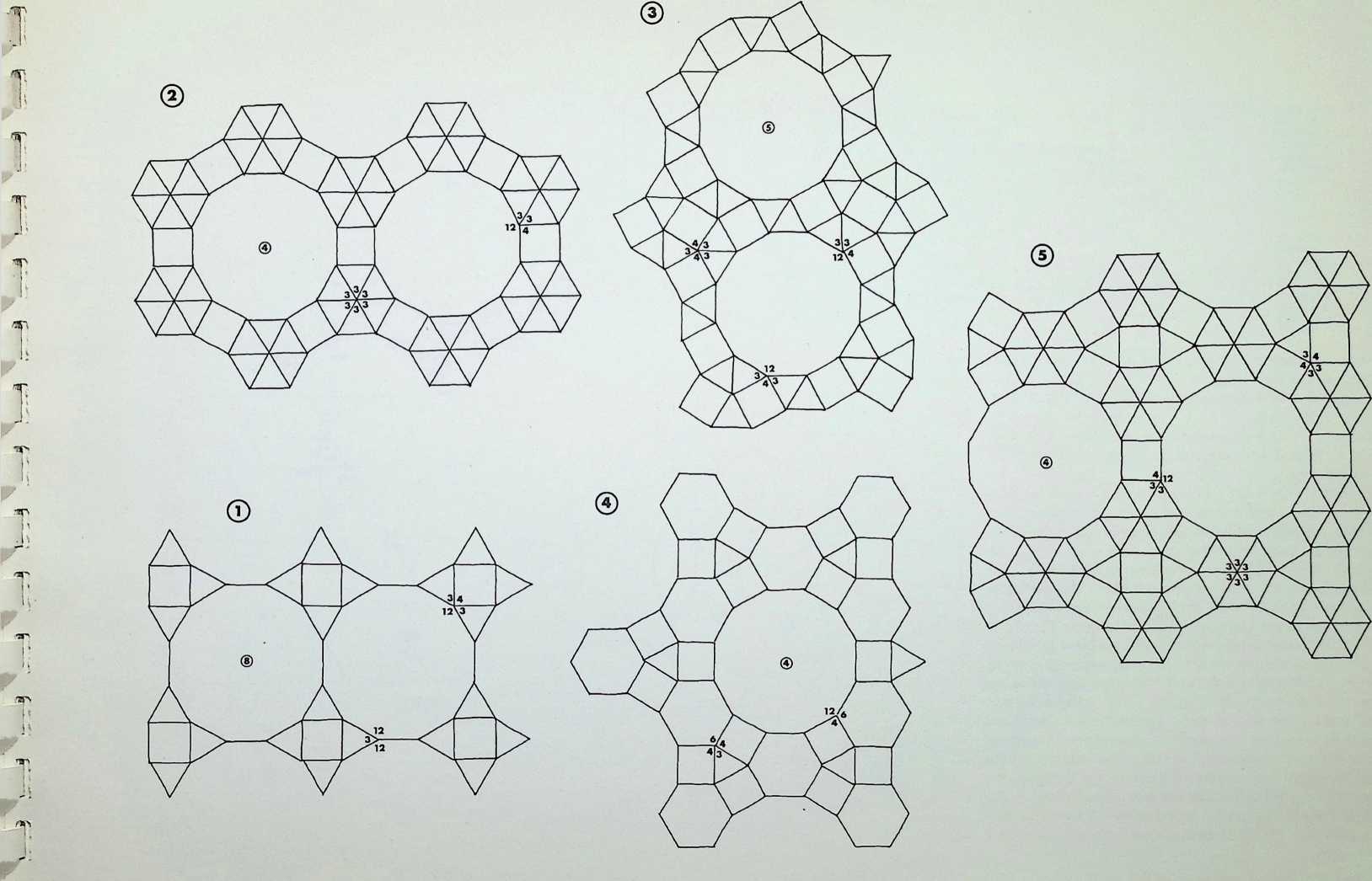
Numbers 6. 7 and 8 of the fourteen demi-regular patterns are illustrated on this page.
Diagram 6 = M + M. with nodal conditions 3, 6, 3, 6; and 6. 6, 3. 3.
Diagram 7 = N + Q1, with nodal conditions 4, 3. 4, 6; and 3, 4, 3. 3, 4 analogous to pattern 1 of the semiregular patterns.
Diagram 8 = N + Q2 + Q1, with nodal conditions 4, 3. 4, 6; 3. 3. 3. 4. 4; and 3. 3, 4. 3. 4 - analogous to pattern 3.
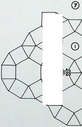
Above the main diagrams are laid out the nodal conditions of all fourteen of the demi-regular patterns, with the total range of polygons meeting at each point. The numbers follow the order of appearance in this particular arrangement starting with the regular equipartitions (1) following on to the eight semi-regular patterns (2). So in the first illustration on the right, where we have 9, instead of the numerical expression 3,12, 3,4 we have a full triangle, dodecagon, triangle and square fitting together around the common nodal condition (ringed). This schema follows for all the figures. Above these graphic nodal conditions there is the numerical values of the areas of the constituent shapes in terms of unit edge lengths. The numbers in the circles represent the number of sides of the polygon, the numbers following these give the area values when multiplied by the edge length (L) to the power of two. The total areas coming together at each ringed node are given as T above each.
T
I ■
T
11
+:-----------------+:-------------------+:-----------------+:----------------------+:-------------------------------------------------+
| ® = 11 19615L2 | © = 0-43301L2 x6 | © = 11 19615L2 | ::: minipage | © = 11 19615L2 © = 2 69808L2 ® = 1 OOOOOL2 |
| | | | > ® - 0 43301L2 x3 | |
| ® - 1 OOOOOL2 | | ® = 1 OOOOOL2 | > | |
| | | | > © = 1 -OOOOOL2 x2 | |
| @ = 0-86602L2 | | ® = 0 866O2L2 | ::: | |
±-----------------±-------------------±-----------------±----------------------±-------------------------------------------------+
| T = 13 06217L2 | T = 2 59808L2 | T = 13-06217L2 | T = 3 29903L2 | T = 14 79423L2 |
±-----------------±-------------------±-----------------±----------------------±-------------------------------------------------+
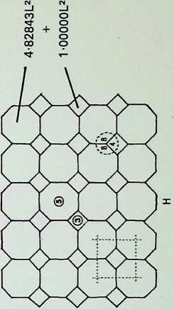
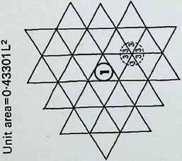
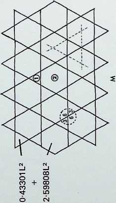
+:-----------------+:---------------------+:-------------------+:---------------------+
| = 2-59808L2 | ::: minipage | © = 1 OOOOOL2 x2 | ::: minipage |
| | > © = 2-59808L2 x2 | | © = 259808L2 |
| = 1 OOOOOL2 x2 | > | © = 0 86602L2 x3 | |
| | > © = 0 86602L2 x2 | | > ® = 1 OOOOOL2 x2 |
| = 0 86602L2 | ::: | | |
| | | | © = 0 86602L2 |
| | | | ::: |
±-----------------±---------------------±-------------------±---------------------+
| = 5-03109L2 | T = 6-06218L2 | T = 3 29903L2 | T = 5-03109L2 |
±-----------------±---------------------±-------------------±---------------------+
L=edge length T=total area covered by constituent polygons surrounding each node numbers indicate occurrence in regular, semi-regular and demiregular two- dimensional patterns


On this page the remaining six demi-regular patterns are illustrated.
Diagram 9 = Q1 + (1). with nodal conditions 4, 3. 4. 3. 3; and 3, 3. 3. 3, 3, 3 - analogous to pattern 6 of the semiregular patterns.
Diagram 10 = Q1 + (1), with nodal conditions 3. 3. 4. 3.
4 and 3. 3. 3. 3, 3, 3 analogous to pattern 2.
Diagram 11 = Q2 + Q1 + (1). with nodal conditions 3, 3, 3. 4, 4; 3, 3. 4. 3. 4; and 3, 3. 3. 3. 3, 3 analogous to pattern 6.
Diagram 12 = Q2 + Q1 + (1), with nodal conditions 3, 3, 3, 4, 4; 3, 3, 4, 3. 4; and 3, 3, 3, 3, 3, 3 analogous to pattern 4.
Diagram 13 = N + N, with nodal conditions 4. 4, 3, 6; and 4, 3, 4, 6 analogous to pattern 4.
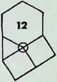
Diagram 14 = N + Q2, with nodal conditions 4, 3, 4, 6; and 3, 3. 3. 4. 4 analogous to pattern 7.
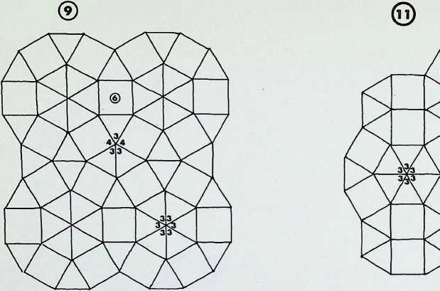
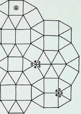
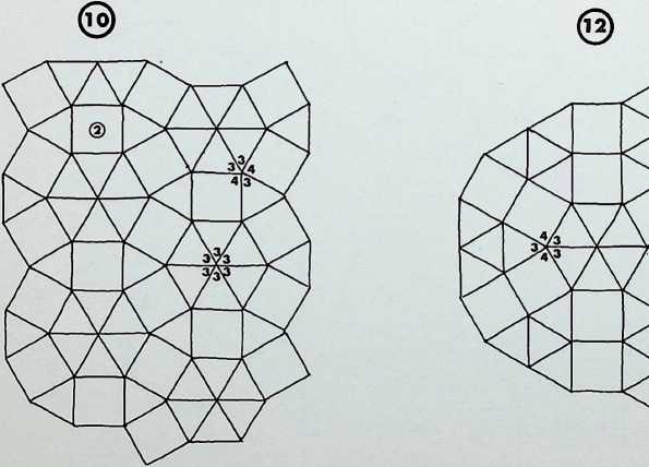
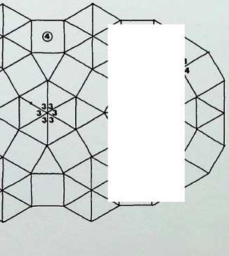
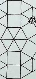
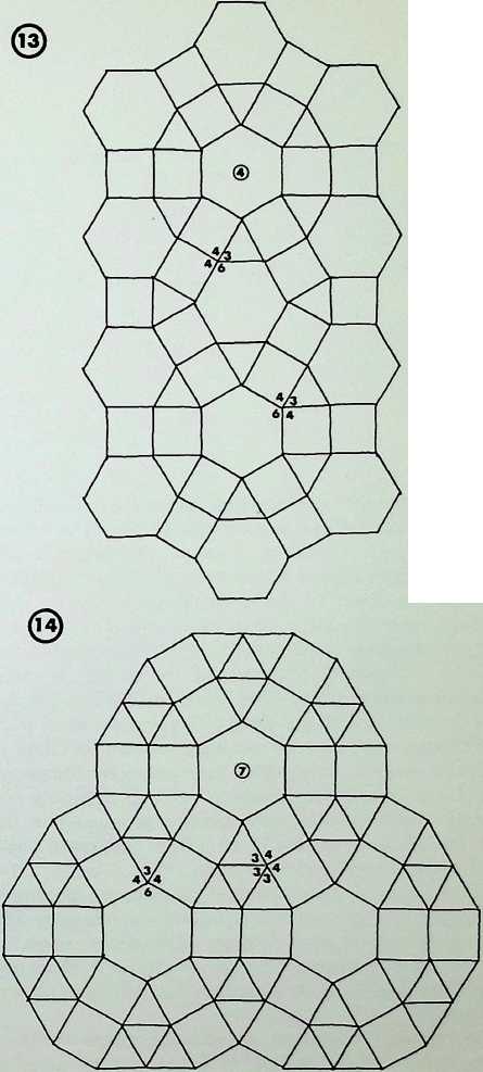
The shapes shown here represent patterns extracted from the semi-regular lattices, known mathematically as closed paths on a given lattice, i.e. a certain number of moves which completes a cycle within the grid and returns to the starting-point. Each of the different grids has its own infinite number of closed paths or shapes. These have a constant character determined by their governing lattices, and can in certain instances be combined as two- dimensional space fillers. They could be used as graphic signs or invested with the value of a symbol many have already been invested with symbolic content. Because of their mathematical universality they could be chosen as signs for a universal language existing alphabets and characters need not then suffer dilution by adaptation, but could still survive in parallel as the cultural heritage of a new world-wide communications system.
All the shapes or closed paths in the three groups shown here are derived from the first three semi-regular grids. The dotted lines show further possible subdivisions. There are fourteen, seventeen and nineteen shapes in each of the groups, but these are only a sample of an infinite number of possibilities.
The numerals contained within each shape represent the number of moves required to define it or the sides to the shape.
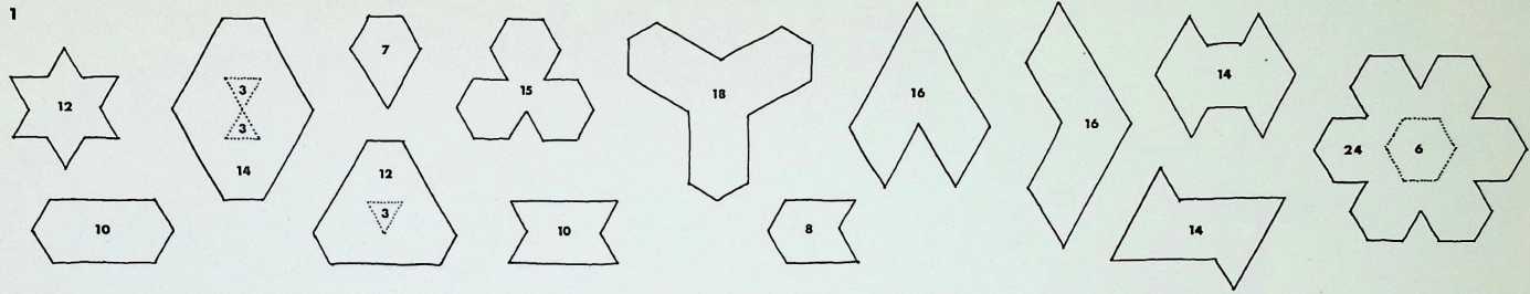
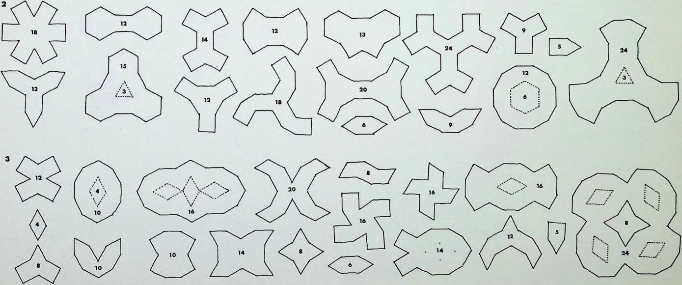
Groups 4, 5 and 6 of the semi-regular grids give us the sets of shapes or closed-path patterns shown here.
■ -T
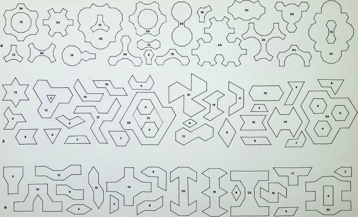
The remaining two families of shapes of the semi-regular lattices are shown here.
72
73
li
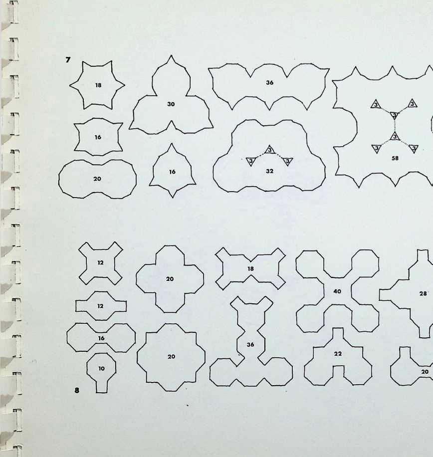
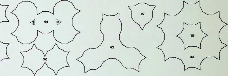
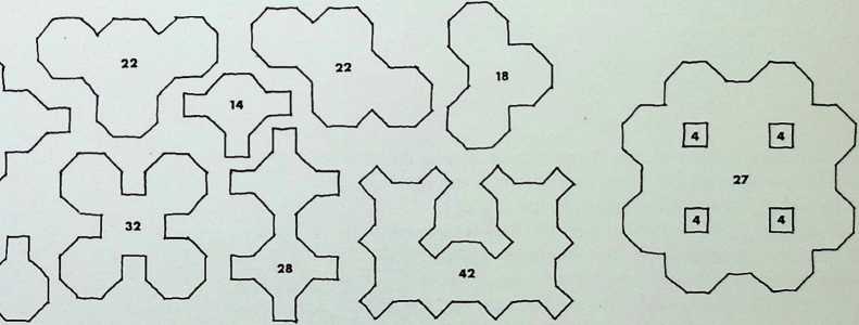
In the interpretation of the three regular and eight semi-regular patterns shown here, we revert to the concept of the touching of spherical points in the plane.
Drawings 1, 2 and 3 show the three regular ways spherepoints can be arranged. The triangular pattern, 1, is the closest packed for economy; the hexagon, 2. is the most economic for distribution over the surface; and the square. 3, takes a mid-position in coverage and packing.
The patterns of the semi-regular divisions of the surface are shown in drawings A-H. The spherical point shown here in each instance as a circle takes up the nodal position or vertex. On the right-hand side of the page are the results of analysing the eight patterns as inscribed circles a-h. The values of the circle radii given are related to the surrounding polygon having a unit edge length.
PATTERNS FORMED BY INSCRIBING CIRCLES IN THE EIGHT SEMI-REGULAR GRIDS
NUMBERS INDICATE RADII OF CIRCLES WITH UNIT EDGE LENGTH POLYGONS
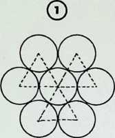
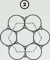
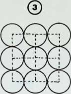
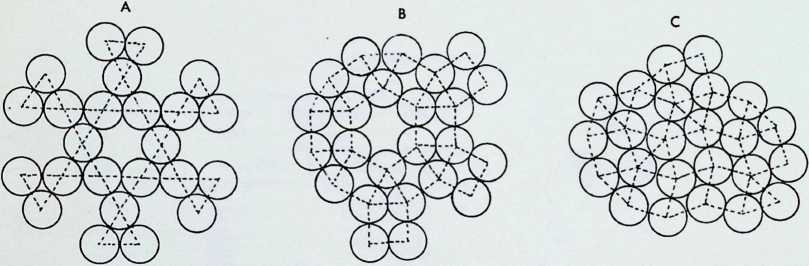
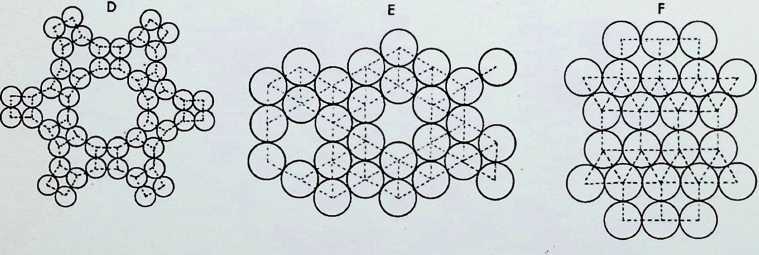
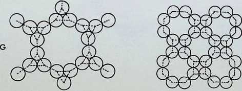
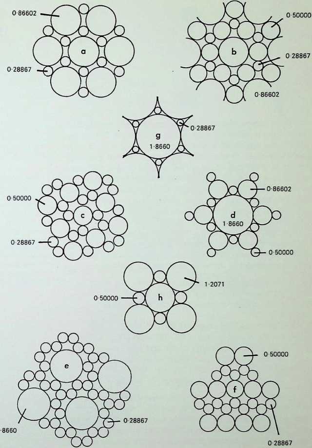
Here the nature of duality of the regular, semi-regular and demi-regular patterns is analysed. The dual is formed by taking the centre of a shape and regarding it as a new vertex or node; these nodes are linked so that the connections cross the edges of the original shapes half-way along at an angle of 90°. We find that the first two of the three regular equipartitions. A, B, C. reciprocate each other,
- e. the dual of the triangular pattern is the hexagon and vice versa. The square is its own dual.
The semi-regular patterns, 1–8, each have their characteristic dual. These are isolated on the top right-hand corner of the page and numbered according to their occurrence in the arrangement of the eight semi-regular patterns:
-
a diamond shape, can be seen to be the result of joining two equilateral triangles:
-
a kite shape, or trapezium, has angles of 60°, 90° and 120°;
-
a pentagon, has angles of 90° and 120°;
-
a triangle, has angles of 30°, 60°, and 90°;
-
a pentagon, has angles of 60° and 120°;
-
another pentagon, has angles of 30° and 120°;
-
a triangle, has angles of 30° and 120°:
-
another triangle, has angles of 45° and 90°.
In analysing the fourteen demi-regular patterns, one of which is shown middle right, we find that the regular hexagon (B) recurs, but only four new duals occur (9, 10, 11, 12). In the ninth of the fourteen demi-regular patterns shown here, the squares of the original are in tone and the duals in broken line. In demi-regular grids on the following pages only the duals have been indicated in tone to avoid confusion.
An analysis of the nature of the duality of the regular, semi-regular and demi-regular patterns; the dual is formed by taking the centre of a shape and regarding it as a new vertex or node.
In an analysis of the fourteen demi-regular patterns, one of which (the ninth) is shown on the right, the regular hexagon. B. recurs, but only four new duals occur , 10, 11, 12 as shown below. In the ninth demi-regular pattern the squares of the original are shaded and the outlines of the duals shown in broken line. In the demi-regular grids shown on the following pages only the duals have been indicated in tone.
6
7
8
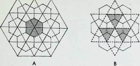
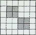
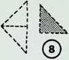


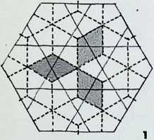
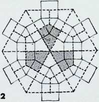
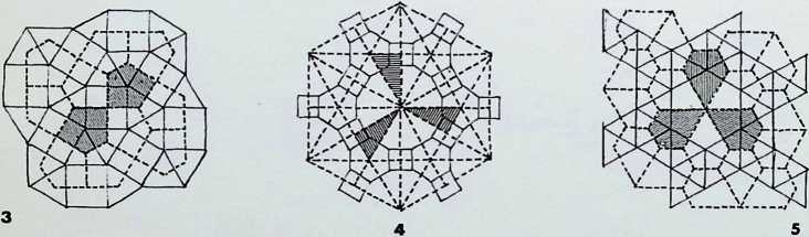
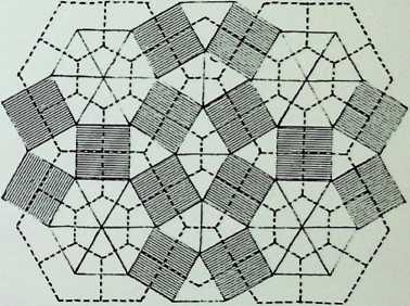
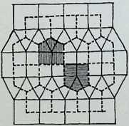
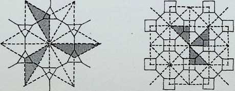


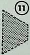
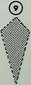
Five of the dual grids of the fourteen demi-regular two- dimensional space-filling lattices are illustrated here. Each lattice is characterized by numbering (ringed) relating to the isolated shapes on the previous page. The duals are shown shaded. The nodal or vertex conditions are characterized by the numerical system employed in the first equation for determining the regular, semi-regular and demi-regular patterns. In these cases, we get 5s appearing when they cannot occur in a regular sense, as the regular pentagon cannot space-fill two-dimensionally. When regular pentagons are placed edge to edge interstice shapes invariably occur.
The centre pattern is an enantiomorphic pattern, i.e. it can be mirrored to spin the other way. It will be readily seen that these grids give rise to an unlimited series of possibilities for closed paths or over-shapes.
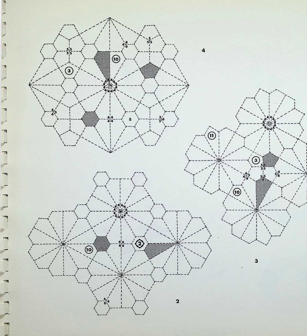
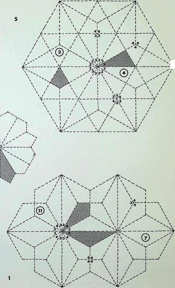
Five further examples of the dual lattices of the fourteen demi-regular divisions of a plane surface are shown here. As on the previous page, each dual is numbered and one example shown shaded. The nodal or vertex conditions are characterized with the numbers of side of each polygon meeting at that point. As before, many subsidiary patterns, closed-path circuits and over-shapes emerge from these and can easily be followed by the eye, e.g. A and B.
8
6
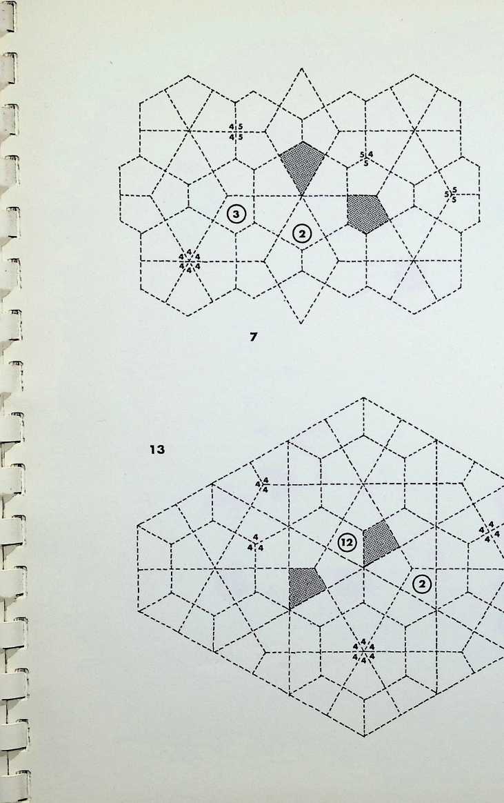
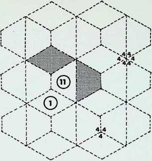
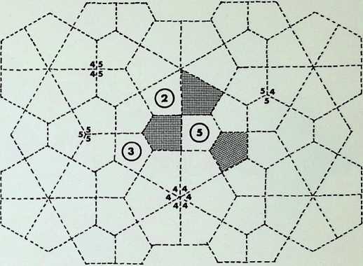
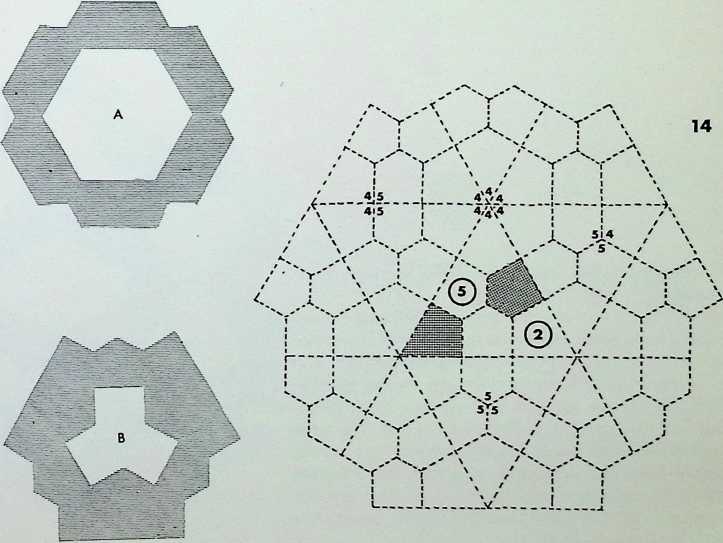
Shown here are the last four duals of the fourteen demiregular patterns.
The pattern at the top left is shown with a minimal closed-path circuit. Flanking the pattern at the top right is another, taken to include symmetrically both characteristic dual shapes. At the bottom centre of the page are the first five closed circuits on the top left grid pattern, each circuit enclosing and non-contacting the previous one. The fields between the paths are shaded alternatively. These can be visualized as infinitely generating rings from the first path. All patterns contain such encircling closed-path circuits. All the patterns on this page have the regular hexagon in common, characterized as A.
12
11
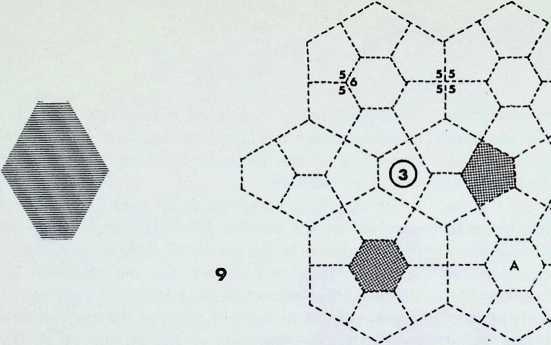
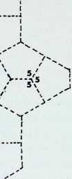
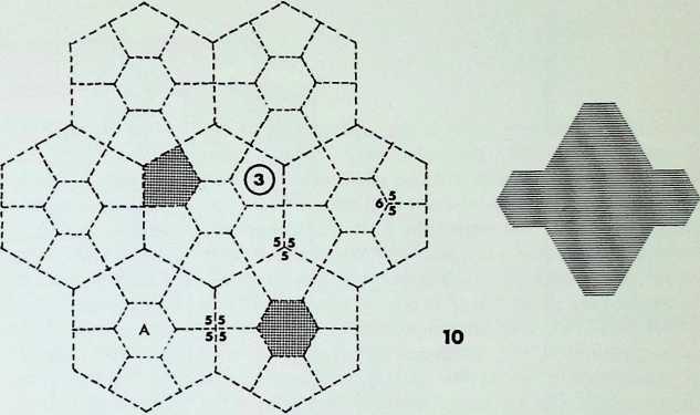
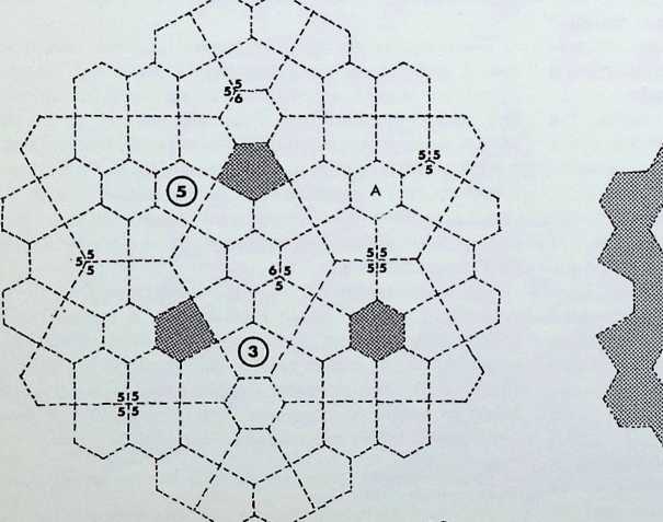
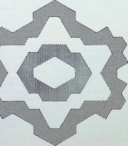
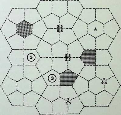
The proportional systems used in the architecture of the past were most probably generated from the two configurations of twelve spheres in close packing shown in A and B on the left. This can be expressed geometrically, on a plane surface, as in A1, where the relationship between diminishing proportional triangles and hexagons is shown. The mathematical ratio of 1 : V3 is expressed in the drawing by the lengths: from 1 to 2 = one unit, and from 1 to 3 = V3 or 1-732051. This system is particularly evident in Gothic architecture not altogether surprisingly in view of the importance given to the triangle and hexagon as Christian symbols. The equilateral triangle is regarded as the symbol of the Trinity; the hexagon the Christians inherited from Judaism, in which it appeared as the Star of David - the sixfold symbol of creation and perfection expressed in divine power, majesty, wisdom, love, mercy and justice.1
In the religions of the Orient we find the Hindu tri-unity, Brahma, Vishnu and Shiva, while for the Japanese Zen the triangle is the symbol for Heaven. Earth and Man. as it was for the ancient Chinese. Similarly the hexagon and six-pointed star have varying interpretations, all important, in Oriental symbolism, and this accounts for their use in the planning of temples. In India these figures are considered to be the interlocking of the two triangles of Shiva and Shaki, forming the wheel or chakra of Vishnu’. Further east, in the Chinese and Japanese traditions, the influence of the hexagram in the philosophical system known as the Book of Changes is expressed in hexagonal form.
Drawing A2 gives diagrammatic expression to the root 2 harmonic series, known in architecture as Pells series, based on the numerical ratios of 1, 2, 5, 1 2. 29. 70. etc. The numerical value of root 2 is 1-414214 the diagonal of a square with side equal to unit length.2 In drawing A2 from 1 to 2 is unit length, the diagonal from 1 to 3 is root 2. Thus one can follow the harmonic diminution. This system of proportion is associated also with the octagon, rstuvwyz, contained within the pattern. Both the square and the octagon are fundamental, and universal, cultural symbols.
Thus we have the four elements of the Ancients and of the Alchemists - Earth. Air. Fire and Water - and the four Gospels of Christianity, while the square is traditionally the geometric symbol of earth, the fabric of the architectural edifice. The square is also the predominant pattern for the Hindu and Buddhist man data or yantra. which is considered a basic psycho-cosmic symbol both on the individual scale and collectively on the temple scale. The number eight is associated with the sum of the seven planets and earth and with the notes of the musical octave; in Christianity eight is the number of the Resurrection, and this is reflected in the octagonal design of fonts.3 In the Sufi tradition emphasis is laid on the octagon as the arena, while in the Buddhist tradition the noble eightfold path may well be directly connected with the predominance of the octagon as a plan shape for the pagoda, the sacred edifice. In the Chinese classic of change, the / Ching, the full number of changes is eight to the power of two. i.e. multiplied by itself.
Drawing B1 shows a progression of pentacles; the diagram is self-illustrating in terms of the relationship of the stars to each other. The harmonic nature of the progression is expressed in the fact that the relationship between 1 (bottom right) and A is a Golden Mean proportion to the length between 1 and 2. Also the distance from A to 2 is equal to that between 2 and 3. This ratio is based on the extreme mean proportion, i.e. in any given line, say from A to B. there is a position, x. on the line so that the distance from A to x is greater than that from x to B and in the same proportion as the whole line AB is larger than the distance from A to x. This is expressed as a fraction
1 +y5 = 1-168033
2
and the result, like the other proportional fractions, is an irrational number,4 i.e. it will not resolve into a whole number. Pythagoras is credited with having discovered the proportional lengths of taut string to musical sound, and these relationships are associated with length proportions taken from drawing B1. As an architectural tool this system of proportioning has been extensively used in Western cultures - from the Egyptians onward. Its modern use was embodied in the work of Le Corbusier, in collaboration with Elsa Maillard.
On the right, drawings C. C1 and C2 show the method used to form a Golden Mean rectangle. The diagonal of half a square is the basis of unfolding a Golden Mean rectangle from that square. On the diagonal 3 of the Golden Mean rectangle thus formed (drawing C1) a right angle is struck at the mid-point of the original square. 4. to meet the extended side of the square at 5. The second rectangle thus formed is made up of two Golden Mean rectangles. The original square can be subdivided into four larger and eight smaller Golden Mean rectangles (drawing C2).
The combination A1 + A2 shows how the root 3 and root 2 systems can be integrated. A circle and inscribed square are drawn, and within this square a further circle and square are inscribed. From the second square two parallel sides are extended until they meet the first circle at 2 ; the rectangle formed is a root 3 rectangle, and a rhomboid based on two equilateral triangles is shown within it to emphasize the shape. This process is repeated three times in all in the drawing. This is thought to be a master diagram for Gothic cathedrals.
The combination A2 + B1 is a well-known method of reducing a Golden Mean rectangle by a square on the smaller side, leaving each time another Golden Mean rectangle whose longer side is now equal to the previous shorter side. This generates a logarithmic spiral commonly found in botanical structures. The drawing shows seven diminutions of this progression.
-
George Ferguson. Signs and Symbols in Christian Art (Oxford University Press. 1961).
-
Professor R. Buckminster Fuller has proposed that the diagonal should be regarded as unit length.
-
See George Ferguson, op. cit. (footnote 1).
-
Eudoxus, in the 4th century [bc.]{.smallcaps} gave the construction for the golden mean ratio of a given line. i.e. 1 :1.68033.
2

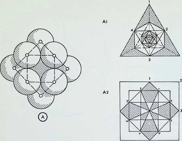
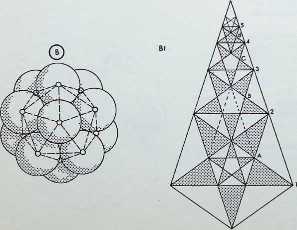
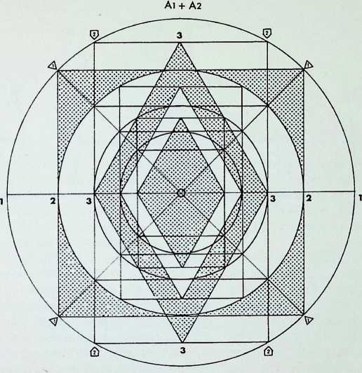
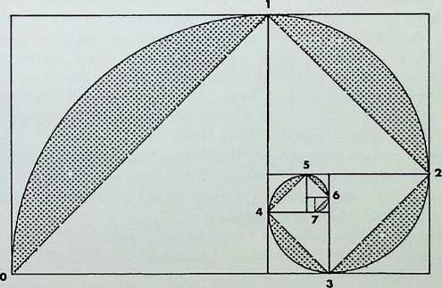

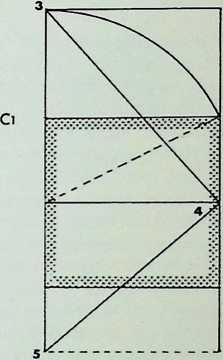
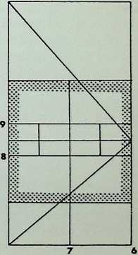
These drawings are to be considered as a possible extension of the methods of teaching spatial appreciation. Here we explore the integration of the first two members of the Archimedean families, the truncated octahedron and truncated icosahedron, (as set out in appendix 1), in relation to human spatial orientation.
This series is built up systematically on the fundamentals of human spatial experience and usage as defined for the charting of dance movements by Rudolf Laban. Central stillness is taken as the starting-point of all movement and its ultimate returning state.1 The first dimensional effort-action is based on the gravity/antigravity movement of growth and establishes relationships above and below the centre - A and B in the centre line of sketches. The next dimensional effort is the gesture of lateral expansion; the establishment of right and left, C and D. Following this is the third dimensional effort-action which establishes the forward and backward movement in relation to the centre E. F. Here the geometrical coordinates x, y, z have been given separate identity on each side of centre lines and are called the six dimensional directions (A, B, C, D, E and F).
Taking the first solid, the truncated octahedron. 1 (top left) as host figure, we can allocate a square to each of the dimensional directions (A, B, C, D, E, F).
In 2, a ‘corner truncated’ version of the three intersecting Golden Mean rectangles of the icosahedron is introduced (see page 31), each representing one of Laban s working planes. The up-down plane A, B, becomes the door plane. The left-right plane C. D. becomes the table plane and the front-back E, F, becomes the wheel plane. The truncation of the planes accords with the use of the truncated icosahedron within the host figure.
In drawing 3 are shown the eight diametrical effort-actions which take up the corners of a cube; to each is allocated a hexagon, i.e. one of the eight hexagonal faces of the truncated octahedron. The eight diametrical effort-actions are gravity-resisting above and gravity-complying below, they are known as: (above) slide, dab. float, and flick (jklg); and (below) press, punch, slash, wring (mnih).
In the next drawing, 4. are introduced the concepts of weight, space and time, relating to the x, y, z axis of the first allocation. This now links weight to gravity or up and down. Space to extension right and left and time to movement forward or back. The qualities controlling the eight effort-actions become light or strong on the weight axis, direct or flexible on the spatial axis, and quick or sustained on the time axis. This drawing shows that eight of the hexagons of the truncated icosahedron sit on faces of the truncated octahedron.
The next drawing. 5, shows how one point of each of the pentagonal faces of the truncated icosahedron touches a square face of the host solid. These pentagons, twelve in all. take up strategic positions, one for each corner of each of the dimensional working planes, thereby giving the ‘door’, table and wheel’ planes thickness and body.
Drawing 6 shows the door and table planes. With linking broken lines indicating the thickness factor. The third or wheel plane is shown separately in 7 to avoid confusion.
Drawing 8 shows the development of movement scales devised by Laban for the dancer to follow through the full patterns and effort scale of the whole of his working space.2
’An interesting parallel to the thirteenth note of silence in John Cage s work in relation to the nuclear sphere - the thirteenth - discussed in this book.
2 For a more detailed study on the work of Laban, see Jane Winearls. Modern Dance (A. & C. Black), and the notes of Laban, Choreutics. edited by Lisa Ullmann (Macdonald and Evans, 1966).

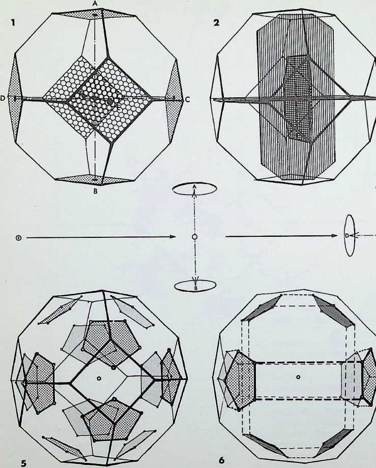
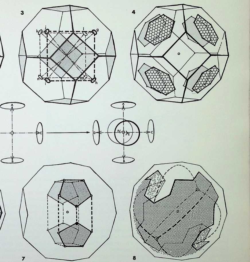
Figure 1 illustrates a multi-directional proportional system, to human scale, based on the truncated octahedron, A-H. The solid is made up of six square faces and eight equal hexagonal faces. The hexagon, as we have seen earlier, has a root 3 ratio of its diagonal to a unit edge. y. The square has a root 2 ratio of its diagonal to a unit edge, x. The ?5 + 1 diagonal of half the square is given as or the Golden Mean ratio to a unit edge, z. Thus the truncated octahedron can generate the root 3 system in thirty-two directions, i.e. from its centre outwards through each of its thirty-two edges. The Golden Mean is generated in eight ways for each of the six square faces; the root 2 system can be generated in two ways in the six directions, from the centre through the six square faces. For example the vector angle for each edge subtended from the centre of the figure is 36° 52, and the vector angle for the diagonal of the square 53° 8.
From this it can be seen that it is possible to generate proportional relationships multi-directionally from a given centre or within a network of events.
The drawing on the right employs the truncated octahedron as an anthropometric and ergonomic space unit. The truncated octahedron is proposed as a basis for determining ergonomic effort assessment and body posture support mechanisms, with the ranges of adjustment required between the three basic postures. The unit can be treated as its own gravitational system or related to a larger gravitational system. The unit gives the possibility of 360° viewing. The theory of this chamber was developed in 1962 with E. Robinson, methods engineer of B.O.A.C. and B.A.C., at Hammersmith College. London.
89
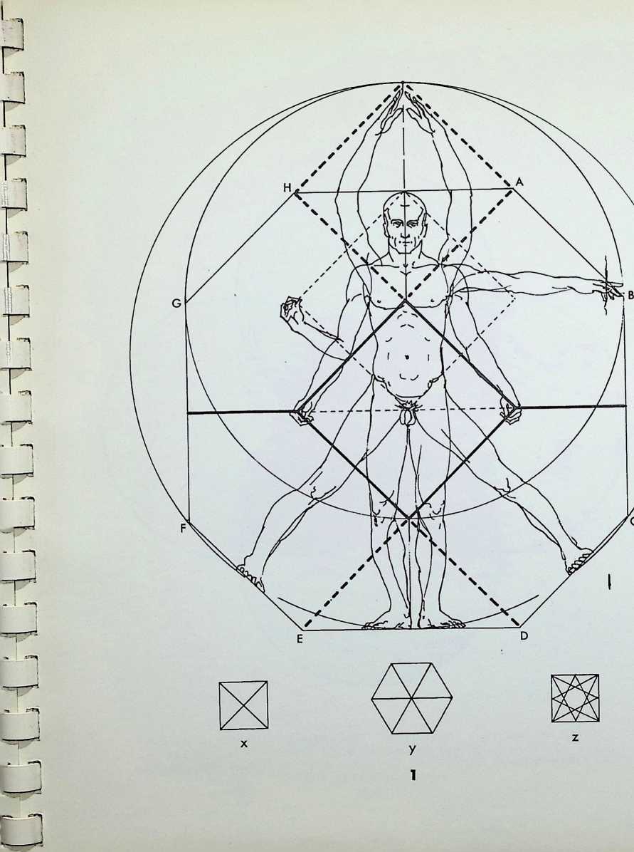
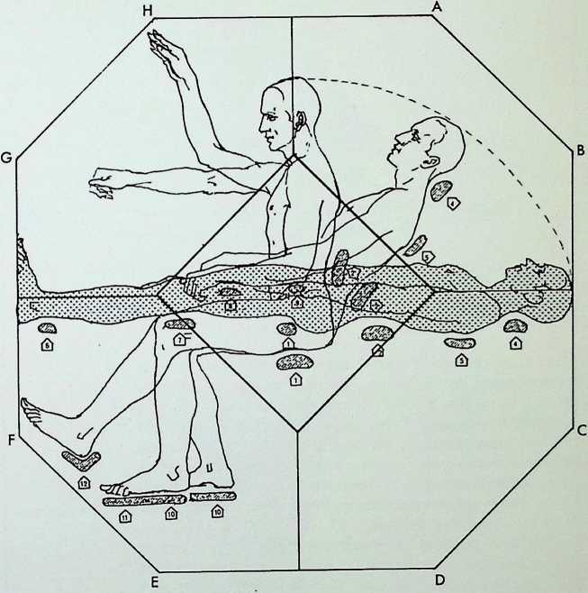
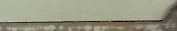
The largest circles in figure 1 represent the primary spheres in tetrahedral configuration, the next in size are overlaid as zones of the points of contact representing the octahedral grouping. These generate the twelve points of contact, represented by the smaller circular zones, making up the dymaxion and consequently icosahedral grouping. This overlay is one way of representing the relationship in a scale which we can describe as three octave diminutions from the initial four spheres.
The next drawing. 2, integrates these three scales of circles with the proportional figure shown in drawing 1 on the previous page. This uses the circles or spheres in a 3, 6, 8 proportion (on the right) to harmonize with a 4, 8,10 system (on the left) derived from the truncated octahedron. Other factors emerge from this system; notably that the edge length of the equilateral triangle from horizontal finger-tips to heels is in root 2 relationship to the edge of the larger square, that is the one inscribed from the knees to the upheld finger-tips. This relationship parallels the edge length of the tetrahedron within a cube of unit edge, which is root 2 to 1.
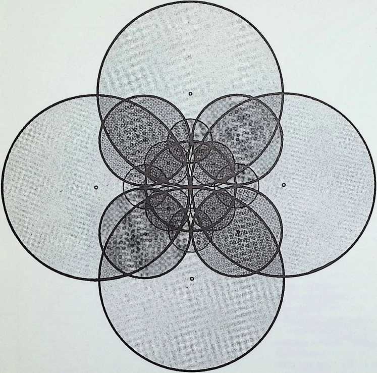
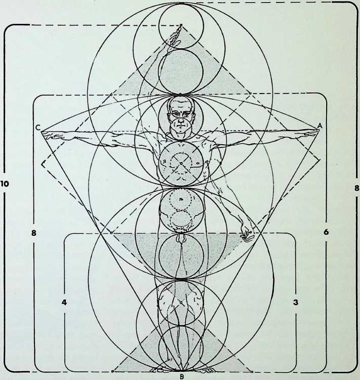
THE OVERLAID POINT-SPHERES OF THE PRIMARY PATTERNS OF ORDER
IN SPACE, THE TOUCHING FOUR BECOMING THE SIX SPHERES OF THE
OCTAHEDRON WHICH IN TURN PRODUCE THE TWELVE POINT-SPHERES OF
THE CUBOCTAHEDRON USING THE THREE OCTAVES OF DIMINUTION SHOWN IN FIGURE 1
AS MODULES IN A ’MAN SCALE
Here, the full rotational lines of symmetry on the icosahedron are analysed.
Thus far we have established that the tetrahedron is the prime plane solid, it is the minimum definition of solid space, and is also the strongest configuration to resist forces from without. The octahedron and the icosahedron complete the range of the three triangulated and structural regular solids. These three figures are the regular representatives of 2, 3, 3-symmetry, 2. 3. 4-symmetry, and 2, 3, 5-symmetry in the solid. The other two regular solids, the cube and dodecahedron, are the duals of the octahedron and icosahedron respectively. The three proportional systems traditionally used in architecture, the root 3. the root 2 and the Golden Mean system, relate to the tetrahedron, octahedron and icosahedron respectively.
From the evolution of the regular solids we further discovered that each of the three triangulated regular solids generated semi-regular figures by truncation, that is by regular cutting off. The tetrahedron produces one figure, the octahedron and icosahedron six each. The unfolded nets of these can be related to the eight semi-regular divisions of a plane surface. From this the idea of duals for both surface figures and solid figures was developed.
From this study of individual characteristics growing out of our initial point, we will now take the icosahedron as the last stage in our evolution, and show how one arrives at the full lines of symmetry on this figure. In 1. at the top left, we have an icosahedron poised between two arrows, with a line of symmetry a a, or meridian, passing through ten faces. The process can be repeated six times, one for each set of poles, giving a set of six meridians. Next we take for poles’ the centre faces of the figure shown in 2. As the faces are parallel to the picture plane, one has to imagine the figure resting on a face as base. By rotation, as before, and inscribing a line around the meridian, we get another set of symmetry lines passing through twelve faces on each full rotation. This can be repeated for each set of polar faces giving ten additional meridian lines. We follow this with rotation on the centre-point of opposite edges as poles’ shown in 3. and find that our symmetry lines pass through four faces and along two edges on each full rotation. This can be repeated fifteen times for each polar set of edges. The combination of this last set of meridians has been shown separately in 4. This process divides each face of the icosahedron into its component 30°. 60°. 90° triangles giving in all sixty light and sixty dark triangles of this type, as shown in the centre drawing. This is the greatest number of equal triangles that an icosahedron can be divided into.
This central drawing gives the full icosahedral lines of symmetry viewed on the 5-fbld axis. The component triangles in dark and light tone respectively (generated from the edge rotation) each contain an equal pattern of dissection by the other lines of symmetry. Those generated by the six apex rotations, indicated by evenly broken lines, quarter each face of the icosahedron. The long and short broken lines are the ten rotations of the face-centred poles. Having obtained these lines of full symmetry and because the icosahedron is the largest number of equilateral triangles that a sphere can be divided into, we return to our beginning to project and analyse this pattern on the sphere in the final drawing, overleaf.
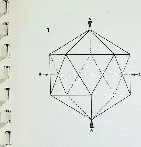
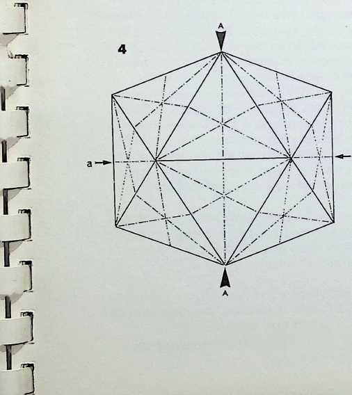
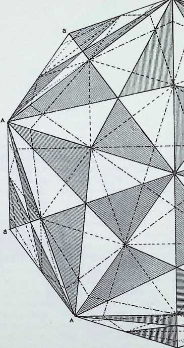
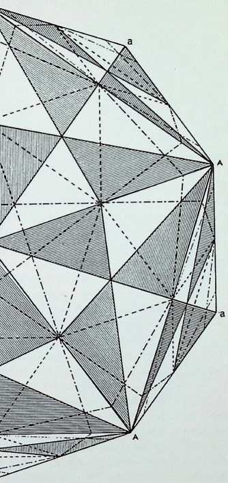
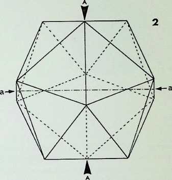
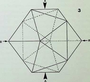
Drawings 1 to 3 repeat, in spherical projection, the rotations of symmetry of the icosahedron, determined on the previous page on the plane figure. It is evident that on the sphere all meridian lines become equal in length and are great circles a great circle being the largest section that can be taken through a sphere, invariably passing through the centre. On the surface of the sphere the shortest, hence most economical, distance between any two points will be on the path of a great circle. This standard of economy is known as geodesics.[11]
Having determined all the great circles of symmetry by the same procedure as for the plane figure, we arrive at six great circles generated from rotation on the points or apices of the icosahedron, ten great circles generated by the centre faces of the icosahedron in 3. and fifteen great circles generated from the centre edges of the figure.
The large central drawing shows a full projection of all the meridian great circles. The icosahedron is shown in its 3-fold axis, that is with the centre of a triangular face towards the eye, outlined in heavy broken line. If we analyse the relationships, we find that we have come to a series of divisions of the sphere on which all the primary figures of our geometric evolution can be described. If we start with the icosahedral face, marked with the symbol I within a triangle, we can see that it is composed of three dark and three light triangles as in the plane version, on the previous page.
If we add three more such triangles to each edge of this face of the icosahedron we can see that we have a larger spherical triangle. O or 0. composed of fifteen of the basic triangles. As we know that there are 120 such basic triangles in the whole sphere, we also know that fifteen divides the whole into eight. Hence we know that our second spherical triangle is the face of the spherical octahedron. If we now take the half-way point of the octahedral face, indicated by a small c in a triangle, and follow the paths of the lines of symmetry across the face each way, we find we have another triangle exactly one- quarter the size of the spherical octahedron face if we follow this around the sphere, we find it to be the spherical dymaxion or cuboctahedron, that is the pattern of the twelve points around a nuclear point, and the points of contact between the octahedral spheres. If we return to our initial icosahedral face, we find that it too is intersected half-way along each edge by the six great circles. This truncates the icosahedron and is the figure we found described between the points of contact of the icosahedral spheres. So we also have the spherical icosidodecahedron (see page 37, drawing 8).
If we reconsider both positions for the octahedral face, and follow the great circles on which its points rest until they meet, we arrive at three points, marked T, falling just inside our projection. If we carefully add up the basic triangles that make up this largest spherical triangle, we find that it contains 30. Again if we divide our whole number for the sphere of 120 basic triangles, we find that 30 is exactly one-quarter of the whole and therefore this is the spherical projection of the tetrahedron.
In 4 a face of the spherical tetrahedron is isolated; in 5 a face of the spherical octahedron in one of its two possible positions is shown (within the outline of the tetrahedral face), while in 6 the spherical cuboctahedron or dymaxion is shown, the icosahedral face being indicated by a dotted line 1. Because of the two possible positions for the spherical octahedron it follows that there are two positions for the spherical dymaxion marked in figure 6 with a small triangle, one for each face position of the octahedron.
The tetrahedron and the icosahedron faces have one position each, within this pattern, reflecting the beginning and end of our first evolution (page 11). The movement or apparent gyration between the positions of the spherical dymaxions and the icosahedron reflects the gyration that takes place in the closing down from the twelve spherepoints of the dymaxion into the structural configuration of the icosahedron.
This concludes our explorations, showing that the sphere can be both a starting-point for evolving a hierarchy of the individual finits plane geometries and a resolution of them into the normality of spherical unity.
Be expansive, like the points of the compass, boundless without a limit. Embrace all creation, and none shall be more sheltered or helped than another.
Chuang Tzu. ch. xvii (4th century [bc).]

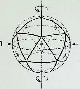
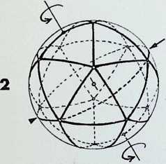
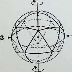
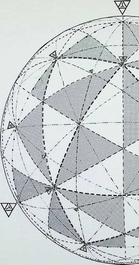
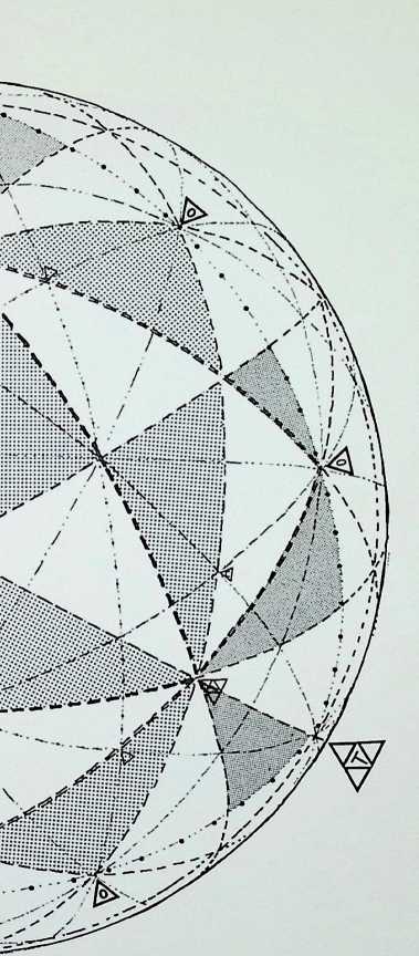
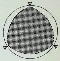
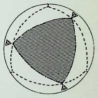
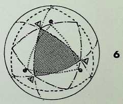
appendix 1
A PERIODIC ARRANGEMENT OF THE ELEMENTS OF SPATIAL ORDER (compiled by the author, 1965)
MEMBERS OF
2, 3, 4-FOLD o
SYMMETRY
Apices
Edges
Faces
Face angles °
Dihedral angles ° 32 3
Circumsphere radius -7321
Intersphere radius
Insphere radius -5774
Centre angle 0 ° 28
Volume -11785 P
THE FIRST REGULAR SOLID
THE TETRAHEDRON or PRIME PLATONIC SOLID
THE SECONDARY REGULAR ‘PARENT SOLIDS
COMPLETING THE FIVE PLATONIC FIGURES
OCTAHEDRON
CUBE or
HEXAHEDRON
Ap. 8
E. 12
SIX TRUN
F.
F.a.
D.a.
C’s.r.
Int’s.r.
Ins.r.
8
60°
109° 28 ’
1-4142
Int’s.r.
0-8165
90°
0-4714013
TRIGONAL PRISM
shown with equal edge lengths
90°
90° J
1-2247
0-7071
C.a. 0 70° 32
Vol. 1 -00000 P
Ap. Ap
E. E.
F. F.
F.a. ° 120° F.a
D.a. ° 16e 109° 28s D.,
C’s.r. -0541 C’
Int’s.r. I nt’
Ins.r. -9487 Ins
C.a. 0 ° 52 C.
Vol. -71 P Vo
PERIODIC ARR
HEXAGONAL PRISM
shown with equal edge lengths-
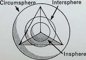
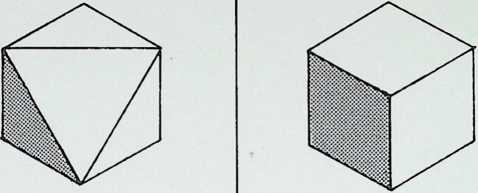
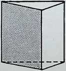
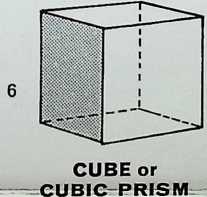
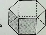
                                                                y/ 7K
                                                                Z \\ / \\ / \\A

     **JBOCTAHEDRON or ‘DYMAXION’**                             **SNUB CUBE**                               **TRUNCATED CUBE**
• Ap. Ap. Ap. Ap.
E. E. E. E.
F. F. F. F.
° 90° F.a. ° 120° 135° F.a. ° 90° F.a. ° 90° F.a.- ° 135°
• ° 16J D.a. ° 44 135°° 16 D.a. ° 14 142° 59 D.a. ° 44 135° 5 D.a. ° 16 90° 5
s.r. -1547 C s.r. -0241 C’s.r. 0773 C’s.r. -0707 C’s.r. -0420
s.r. Ints.r. Ints.r. Int s.r. Int’s.r.
.r. -8660 Ins.r. -9765 Ins.r. -9282 Ins.r. -9340 Ins.r. -9597
. 0 ° C.a. 0 ° 55 C.a. 0 ° 41 C.a. 0 ° 53 C.a. 0 ° 39
. -37 /3 Vol. -63 /3 Vol. -68 /’ Vol. -74 /3 Vol. -76 /3
ANGEMENT OF THE SINGLE ALL-SPACE FILLING SOLIDS
hierarchy of vij minimal surface to V maximum interior space
SNUB TETRAHEDRON
TRUNCATED
4
TWIST RHOMBIC DODECAHEDRON
RHOMBHEX
DODECAHEDRON
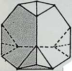
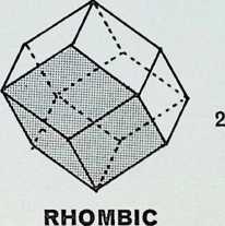
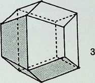
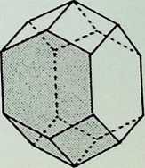
o ar.
<
LU
W ZP z
uu
X
Apices Ap. Ap. A
Edges E. E. E.
Faces F. F. 8 F.
Face angles ° 90° F.a. ° F.a. ° 120° F,
Dihedral angles ° ‘ 90°4 D.a. ° ‘ D.a. ° 4 90° 4 D
Vol. -00000E3 Vol. -86603H3 4-50000E3 _V
THE THIRTEENTH or NUCLEAR ARCHIMEDEAN SOLID
1 2 3
NOTES ON TERMS USED IN THIS CHART
Regular means that all faces, angles and angles between faces are the same. There are only five, without admitting interpenetration: three are triangulated. Semi-regular means that the faces which make up the solid are in themselves regular, but that there is more than one type of face. Both regular and semi-regular figures lie with all vertices or points in a containing sphere, the circumsphere.
Dihedral means between two faces.
Insphere means the sphere touching the centre of the faces inside the solid.
Intersphere touches the centre edges of the figure.
Apices
Edges
Faces :4
Face angles ° 120°
Dihedral angles 70° 32 s 109° 28s
Circumsphere radius -1055
Intersphere radius
Insphere radius -9045
Centre angle 0 ° 28
Volume -394 P
THE TRUNCATED TETRAHEDRON
with twelve independent axes
MEMBERS OF
2, 3, 5-FOLD
SYMMETRY
Ap.
E.
F.
F.a.
D.a.
C’s.r.
Ints.r.
Ins.r.
C.a. 0
Vol.
12
30
20
[60°]
138° 11
1-1756
1
0-9342
63° 26 •
2-18170 /3
Ap-
E.
F.
F.a.
D.a.
C’s.r.
Ints.r.
Ins.r.
C.a. 0
Vol.
20
30
12
90°
116° 34 5
1 -0705
1
0-8507
41° 49
7-66312 I3
[Ap.]
E.
F.
F.a.
D.a.
C’s.r.
Ints.r.
Ins.r.
C.a. 0
Vol.
32 F
108° 120° F.
142° 37 ‘ 138° 11 e D
1-0210
[1]{.underline} I
0-9794 lr
23° 17
57-56 P
ICOSAHEDRON
DODECAHEDRON
TRUNCATED
ICOSAHEDRON
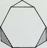
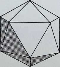
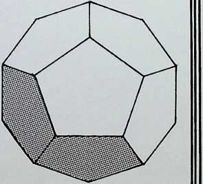
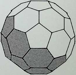
|
Ap. | Ap. | Ap. | Ap. |
|
||||
| (18 unit, 12 lesser) | E. | E. | E. | (18 unit, 3 larger, 3 lesser) | E. | ||||
|
F. | F. | F. | F. | |||||
| • | ° 28 35° 16 120° | F.a. | ° 120° | F.a. | ° 28 | F.a. | ° 28 | F.a. | ° 28° 32 125’ 16 |
| . | ° 44j 70° 32 s | D.a. |
|
D.a. | ° < | D.a. | °, | D.a. | ’ ‘ 120° |
| . | -18198E3 13-85638E3 | Vol. | -31371E3 | Vol. | -07921E3 | Vol. | -079E3 10-388E3 1-299E3 | Vol. | -74586E3 |
4 5 6 7 8
30
60
32
60° 108°
a. 142° 37s
s.r. 10515
’s.r. 1
s.r. 0-9511
a. 0 36°
I- 14-31 I3
ICOSIDODECAHEDRON
Ap. 120
180
150
Ap. 60
E. 120
90
Int’s.r.
Ins.r.
C.a. 0
Vol.
90° 120° 144°
159° 6: 148° 17
142Z-37°
1 -0087
60° 108°
164° 11 152° 56s
1 0280
F. 62
F.a. 60° 90° 108°
D.a. 159° 6’ 148° 17
32
60’ 144°
142° 37 116° 34
Int’s.r.
0-9914
15° 6
21-7913
TRUNCATED
ICOSIDODECAHEDRON
C.a, 0
Vol.
26° 49
37-7213
SNUB DODECAHEDRON
C’s.r.
Int’s.r.
Ins.r.
C.a. 0
1-0260
1
0-9747
25° 52
Int’s.r.
1-0145
Vol. 42-01 I3
RHOMBICOSIDODECA-
[HEDRON]
Ins.r.
C.a. 0
Vol.
0-9857
19° 24
97-4513
TRUNCATED
DODECAHEDRON
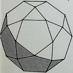
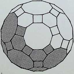
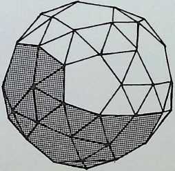
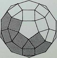
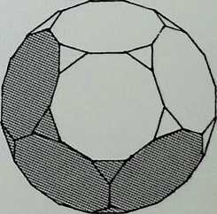
U)
Q
O
CO
CD CD [lA]
CD
CD

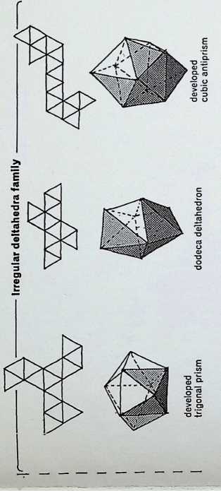
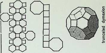
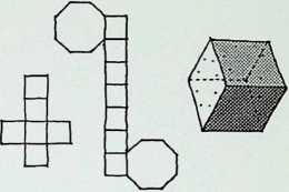
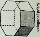
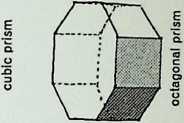
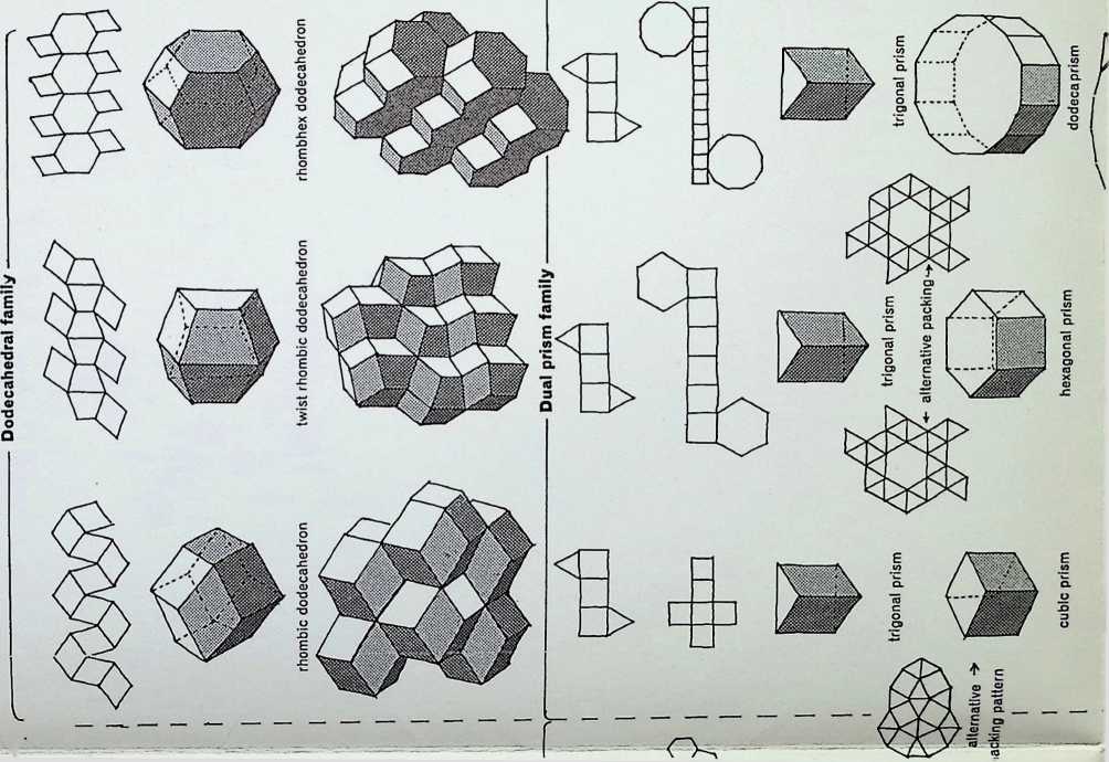
pa?
trigonal prism trigonal prism hexagonal J>nsm
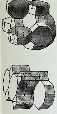
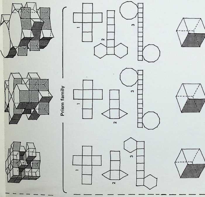
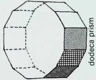
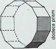
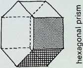

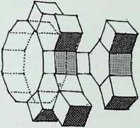
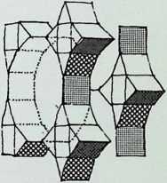
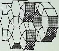
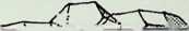
The eight triple all-space filling solids

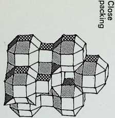
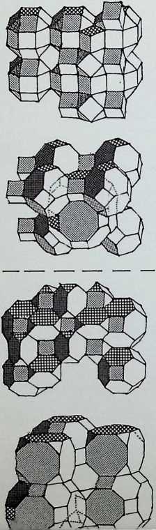
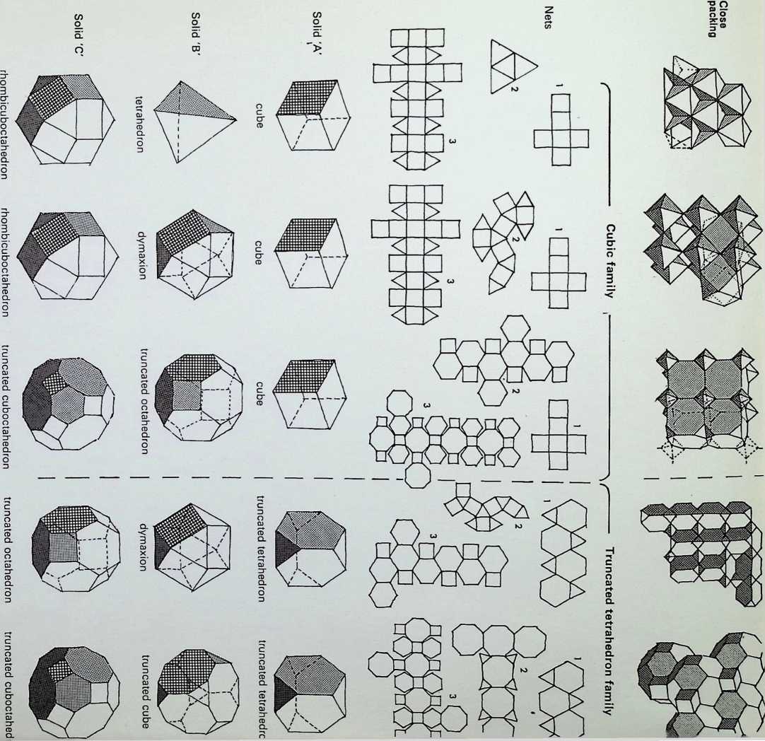
The ten dual all-space filling solids
The eight self all-space filling solids
Multi combination all-space* The eight deltahedra
EXHIB
APPENDIX 3 ASPECTS AND DEFINITIONS
THE FIVE FACTORS OF A CIRCLE
THE FIVE CONIC SECTIONS
arrows indicate line of section through cone.
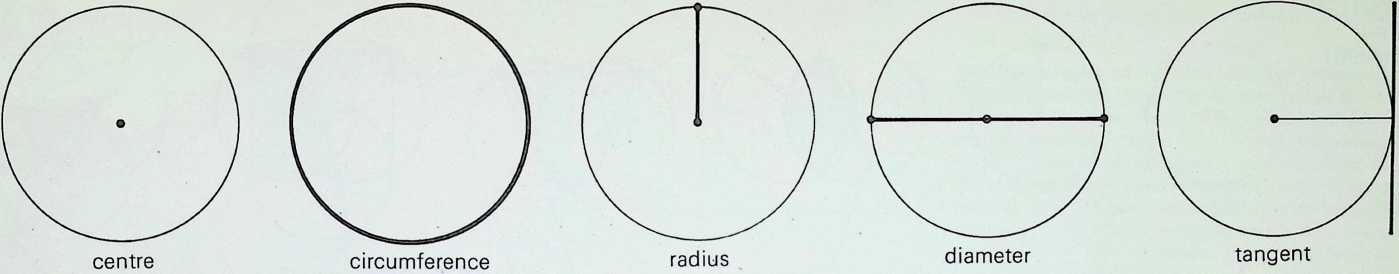
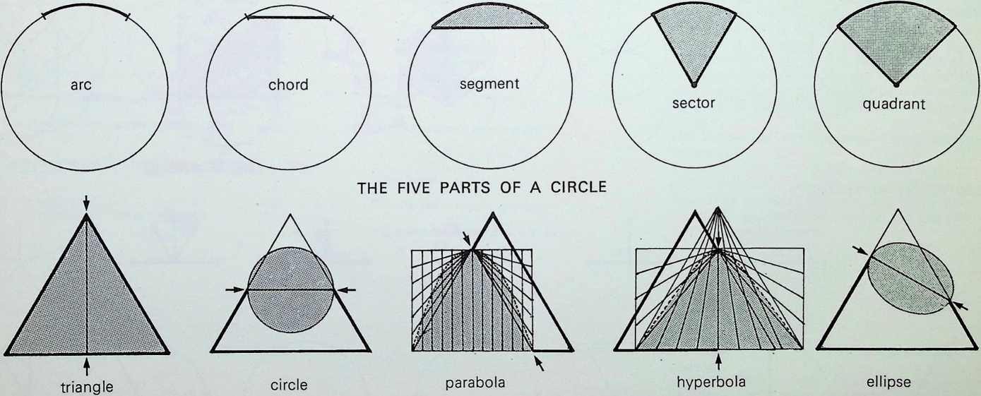
TRIANGULAR EVOLUTION
RHOMBUS
(60° coordination)
TRAPEZIUM
PARALLELOGRAM
QUADRILATERAL
ISOSCELES TRIANGLE
SIGNIFICANT ANGLES
right
acute
DEFINITIONS
supplementary
complementary
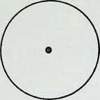
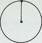
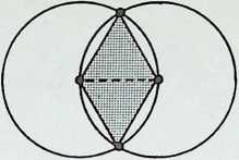
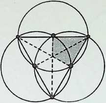
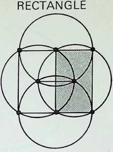
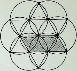
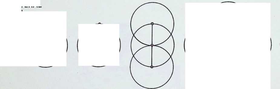
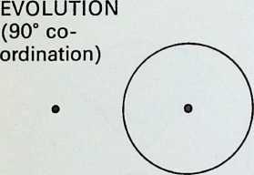
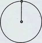
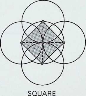
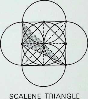
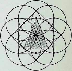


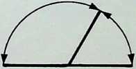
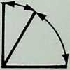
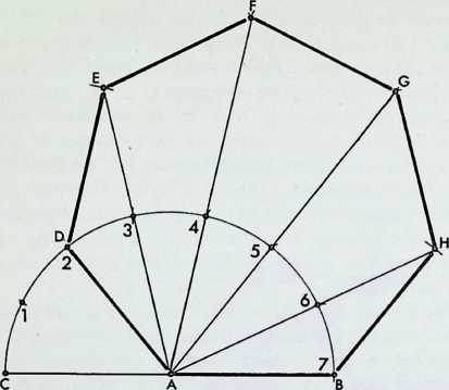
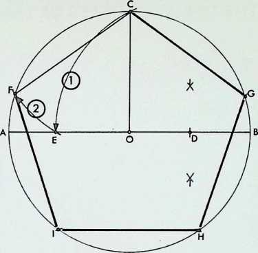
TO CONSTRUCT A REGULAR POLYGON GIVEN EDGE LENGTH
TO CONSTRUCT A REGULAR PENTAGON WITHIN GIVEN CIRCLE
AB=given edge length of regular polygon
A=centre of arc from B through 180° to C
Arc CB is divided by the number of sides of the required polygon
From A produce lines through arc divisions 2. 3.
4, 5. 6
Cut off side lengths at D. E. F. G. H, and join to form polygon, here a heptagon (7 sides)
AB=^ circle or diameter
C=upright from centre. 0. at 90’
D = midway point on radius OB
E=arc from D with radius CD
F=arc from C with radius CE
FC=one side of regular pentagon
CGHIF is completed pentagon within circle
SEMI-REGULAR SOLIDS
The semi-regular solids may be defined in the following three categories:
- Spherically as morphic number patterns
Defined under this heading as representatives of the twelve degrees of freedom around a central nuclear position, as the circumspheres of the semi-regular polyhedra viewed as the closed set of distribution patterns of the spherical surface, morphically as close-packing relationships of these spheres. This has been demonstrated as being a threefold behaviour pattern from truncated tetrahedron, through the equilibrium of the dymaxion. into the final locked icosahedral pattern.
- Linearly in the woven pumping geometry
Each pattern integrity of nodals or zero phases in space describing a semi-regular configuration is a basis for demonstrating the behaviour of pumping geometry. These linear constructions are composed of the interweaving of tetracaps, octacaps and icosacaps and they demonstrate the threefold nature of (a) dominant regular pattern, (b) recessive regular pattern and © intermediate semiregular pattern. The time transformation characteristic of these figures displays the three interdependent solids in action.
- Solidly as the resulting figure after intertruncation
The set of thirteen can also be viewed as the resultant solids after intertruncation between the regular dual solids. These occur once between tetrahedron and tetrahedron and six times between octahedron and cube and icosahedron and dodecahedron respectively.
Overleaf
Models to illustrate right- and left-handed complementary truncated tetrahedral pumping geometry. The axes for a matrix are indicated where the two models meet centrally. The action within the matrix would be complementary or self-compensating, with one configuration contracting as the neighbouring configurations expand, and vice versa. All component members are non-interfering with other members.
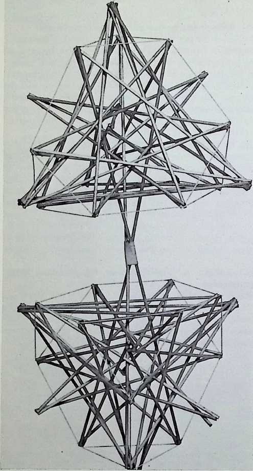
Model: F. Hussain Photo: Tony Jenkins
APPENDIX 4
AN INVESTIGATION INTO ASPECTS
OF THE TWELVE DEGREES OF FREEDOM
The text and drawings contained in this appendix were prepared in 1967 under the auspices of a Shell International Research Scholarship.
We will begin this appendix by taking the minimal expression of points describing volumetric space - four points as spherepoints of the tetrahedron. This configuration divides precessionally into two pairs at 90° to each other. To express the degrees of freedom of regularity in the division of space polyhedrally. we can allocate to these primary spherepoints the icosahedron and dodecahedron. as the co-members of the 2, 3, 5-fold symmetry, and the octahedron and cube as the regular representatives of 2. 3. 4-fold symmetry. The over figure or embracing form, the tetrahedron, completes the full five possible regular polyhedral divisions.
If we now proceed to surround this configuration with the next sphere or shell of close-packed spherepoints we find that we can fit exactly twelve. By the same principle of allocation, we now assign to each of these an Archimedean or semi-regular solid; we find the families divide into six of 2, 3. 5 and six of 2. 3, 4-fold symmetry. The thirteenth, the truncated tetrahedron, completes as the over figure, in the same way as the regular tetrahedron completed the pattern of five regular figures.
We now extract the nuclear tetrahedron of spherepoints, and find ourselves left with twelve spherepoints in unstable equilibrium. This pattern the truncated tetrahedron is the first expression of the twelve degrees of freedom as it is the only one of the Archimedean solids that has twelve independent axes from its centre through its vertices.
It can also be seen to be the first phase of the wind-in which encompasses the dymaxion, at vectorial equilibrium, moving through to the structurally complete and stable icosahedral configuration. We can now present a way of viewing the range from least stable and independent axes, through equilibrium into stability, having traversed the basic symmetries found in nature - starting with the 2. 3. 3- fold (or tetrahedral), through to the 2, 3, 4-fold (or octahedral) into the 2, 3. 5-fold (or icosahedral) symmetry. A certain validity is added to the allocations of the Archimedean solids as they are definite by the fact that their nodes lie in a containing sphere, hence they could be regarded as the economic distribution patterns of points lying in the spherical surface.
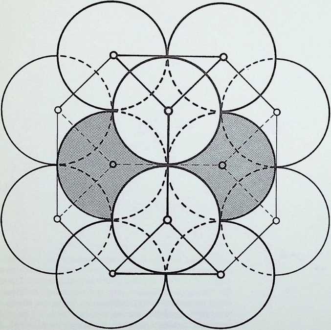
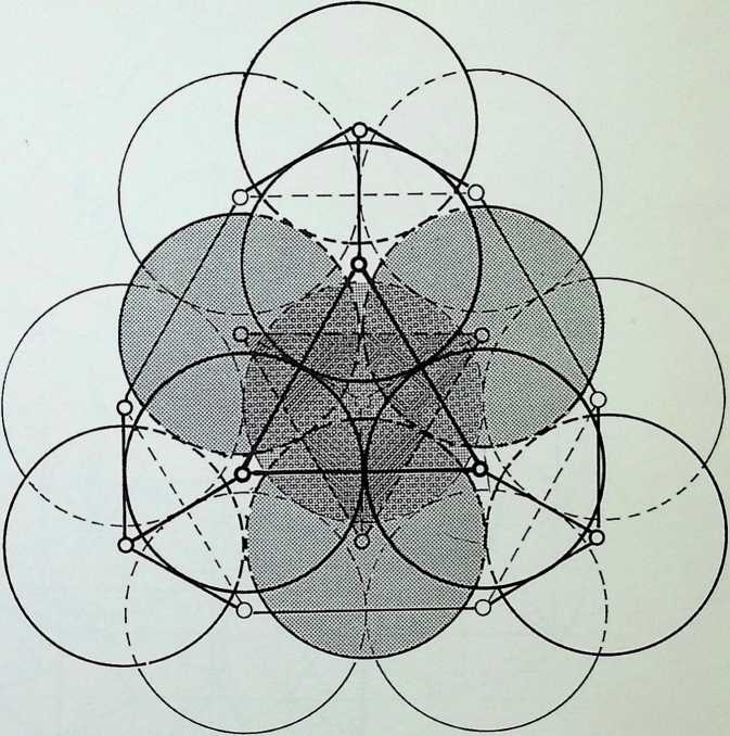
Figure I (1) shows the truncated tetrahedral configuration of closest packed spherepoints around the tetrahedral nucleus (shaded). This drawing is shown on its 2-fold axis, and the centres of the outer truncated tetrahedral grouping have been linked.
Figure I (2) viewsthewhole group of sixteen spherepoints, with the nuclear tetrahedron shaded and the second shell sitting in four groups of three on the four nodal axes, or triangular faces, of the truncated tetrahedron. The centres of the tetrahedral grouping are centre-linked as are the outer centres of the truncated tetrahedron.
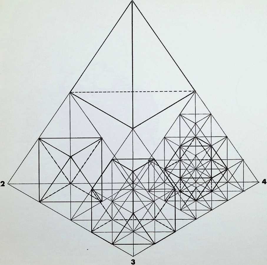
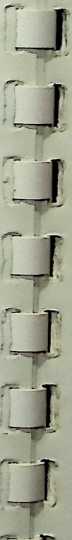
Figure I (4) indicates the nature natural closing in to tighter configui constituent spherepoints. This rotatk place to the right or left. The spherepoir 6 twice to indicate the nature of the all octahedral symmetry and six to the icos the Archimedean figures. Those of the. are shown in the drawing with the nu. (4). (6). (2) is rotating anti-clockwise while group (5). 2.1. and group (1). 3. This gives rise to the conditions where each other (at the centre of the edges o tetrahedron), with three moving in (marked ss) and three moving in (marked oo).
Figure I (3) is one large tetrahedron, subdivided to show the frequency subdivision from one to three. The nodes are numbered 1 to 4: 1 is the undivided tetrahedron; 2 is the first frequency subdivision, giving the octahedral nucleus; 3 is the second frequency subdivision, giving the truncated tetrahedral configuration as nucleus; and 4. the third frequency subdivision, gives a nuclear condition of the dymaxion or cuboctahedron. The drawing contains all the direct neighbour linkages in fine line to show the octahedral and tetrahedral packed nature of the subdivisions.
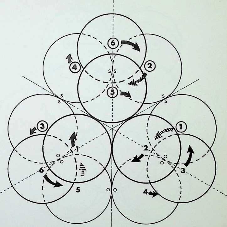
Figure I (4) indicates the nature of the wind-in or natural closing in to tighter configuration of the twelve constituent spherepoints. This rotation inward can take place to the right or left. The spherepoints are numbered 1 to 6 twice to indicate the nature of the allocations of six to the octahedral symmetry and six to the icosahedral symmetry of the Archimedean figures. Those of the octahedral symmetry are shown in the drawing with the numbers ringed. Group (4). (6), (2) is rotating anti-clockwise as is group (3), 6, 5. while group (5). 2.1, and group (1), 3, 4. rotate clockwise. This gives rise to the conditions where the groups contact each other (at the centre of the edges of the basic truncated tetrahedron), with three moving in the same direction (marked ss) and three moving in opposite directions (marked oo).
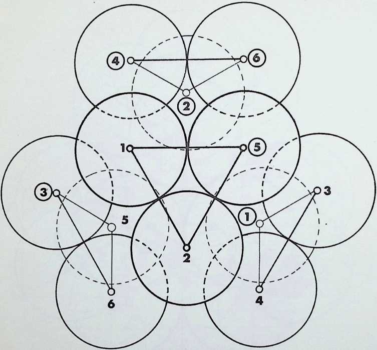
Figure I (5) illustrates the new positions of the spherepoints after rotation by 60°. but placed around the same centre, not having yet moved in toward the centre of the system. In fact the wind-in rotates and spirals in simultaneously. We have kept these movements separate for clarity. It can be seen that the triangular groups now have an edge facing each other which, if linked, would form a system of triangles and rectangles instead of the hexagons of the truncated tetrahedron which it rotated from.
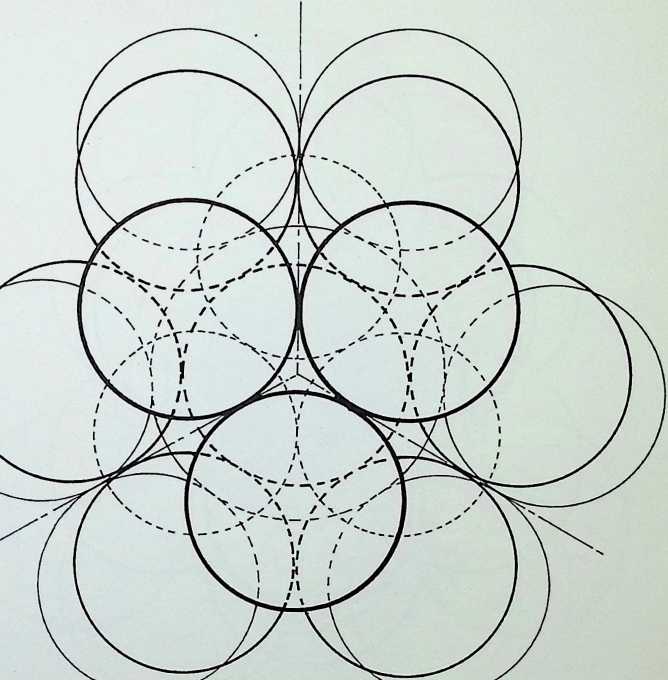
Figure I (6) illustrates the closing in towards the centre from figure I (5) in lighter line to the dymaxion or cuboctahedron in heavier line. Also it has been indicated at this stage of equilibrium that we have the exact space for a nuclear spherepoint, which in terms of the allocation of strictly one spherepoint per Archimedean solid gives us thirteen of equal size, the truncated tetrahedron taking the nuclear position.
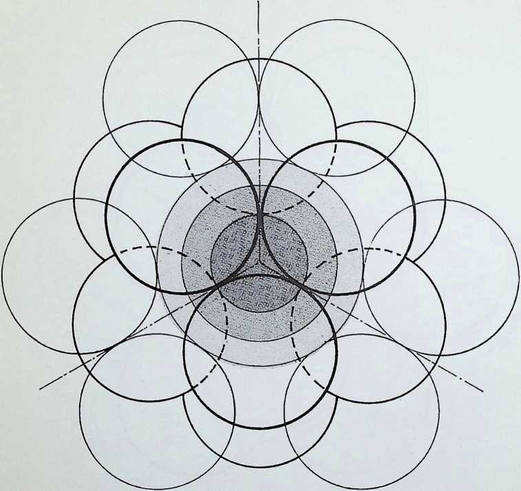
Figure I (7) illustrates the two extremes of the total three-phase wind-in from truncated tetrahedral open to icosahedral closed. The shaded nuclear region shows the nature of the changes in possible size of the nucleus in each position: the larger size for the open truncated tetrahedral position, the mid or equilibrium of the dymaxion with nucleus of equal size to the spherepoints, and finally the smaller nucleus of the icosahedral position. The whole is viewed as indicated on the 3-fold axis.
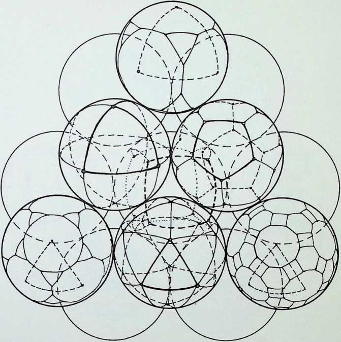
In the second aspect of this exploration figure II (1) demonstrates the nature of the allocations. The central nuclear tetrahedral group is allocated the regular divisions of octahedron, cube, icosahedron and dodecahedron, the over figure being the fifth, the tetrahedron. The top three spherepoints have been lifted off the 3-fold axis of the truncated tetrahedral grouping to reveal the nuclear regular solids, and three neighbouring semi-regular solids have been projected on to the spherepoints of the outer shell. Those shown are truncated cube (top), truncated icosidodecahedron (bottom right), and truncated dodecahedron (bottom left).
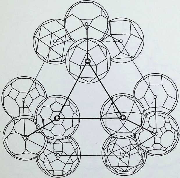
Figure II (2) is an expanded view of all the outer shell spherepoints with their respective Archimedean solid allocations. This excludes the truncated tetrahedron which takes up the over figure as in the regular nucleus. A total number of six representatives of octahedral symmetry and six of icosahedral symmetry are grouped in families, with the icosahedral family positioned in a hexagonal ring below.
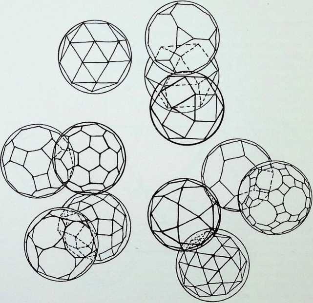
Figure 11(3) shows the rotational action of the spheres as the figure begins its transformation towards the dymaxion or cuboctahedron.
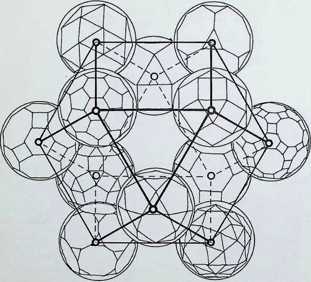
Figure II (4) shows the configuration of equilibrium or dymaxion with the possibility of locating the truncated tetrahedron as nucleus of the same size as the other spherepoints. We have not drawn it in this figure, as it represents a moving stage towards the further contracted icosahedral position where it locks. If the nuclear spherepoint is in position no further contraction can take place.
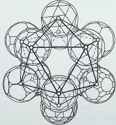
I
J
J
i I
J
J g j
j J j J
Figure II (5) shows the full transformation into the fully locked structural shell in icosahedral pattern. At this point the twelve representative degrees of freedom or twelve possible outer representatives of the semi-regular subdivision of the spherical surface have traversed the three symmetries found in nature’s structuring strategies from the 2. 3. 3-fold (or tetrahedral), through to the 2. 3, 4-fold (or octahedral), and finally into the 2, 3, 5-fold (or icosahedral) symmetry.The parent solids ofthesesymmetries are the three possible configurations of equilateral triangulation of solid space. The structural significance of which has been emphasized by R. Buckminster Fuller.
Summary
In conclusion, we have shown that analogy can be drawn between the behaviour of morphic number (sphericality), the degrees of freedom, and the twelve possible truncations of the regular solids viewed as economic distributions on the circumspheres of the Archimedean solids.
Together with this morphic allocation we have drawn attention to the behaviour pattern of the three major transformations from the truncated tetrahedral packing around a tetrahedral nucleus through to the equilibrium of the dymaxion or cuboctahedral configuration, and finally into the locked icosahedral pattern, traversing the three major omnidirectional symmetries employed in nature. All can be considered phases in the disposition of the twelve degrees of freedom, or the fundamental origin of the twelve orientations of each symmetry, the truncated tetrahedral starting-point being unique in having twelve independent axes from each node to the centre.
Bibliography (in approximate order of complexity)
The Number Story by H. and A. Taussig-Freitag (National Council of Teachers of Mathematics, Washington, D.C.) Mathematical Puzzles and Diversions and More Mathematical Puzzles and Diversions by Martin Gardner (Pelican, Harmondsworth)
Mathematics for the Million by Lancelot Hogben (Pan Piper. London)
Geometry (at the Junior High School Grades and the Waldorf School Plan) by H.V. Baravalle, Ph.D. (Waldorf School, Adelphi College, Garden City, New York)
Practical Geometry for Junior Builders by L.A. Lee and R.F. Reekie (Edward Arnold. London)
Geometry of Construction by T. B. Nichols and N. Keep (Macmillan, London, 1966)
Space Enclosure Systems by D. G. Wood (Eng. Exp. Sta. Bulletin 203, Ohio State University)
Change in Space-defining Systems by Myron A. Guran (University of Oregon)
Mathematical Models by Cundy and Rolled (Oxford University Press)
Hints for Crystal Drawing by M. Reeks (Longmans, London, 1908)
The Elements of Dynamic Symmetry by J. Hambridge (Dover, New York)
The Beautiful Necessity by C. Bragdon (The Manus Press, Rochester, N.Y., 1901. now Alfred A. Knopf)
Perpetual Motion by A.T. Stewart (Heinemann. London. 1968)
Elphyma Tables by E. Ingelstrom and S. Sjbberg (John Wiley. London. 1964)
Solid Geometry by J.S. Hails and E.J. Hopkins (Oxford University Press. 1957)
The Third Dimension in Chemistry by A. F. Wells (Oxford University Press. 1956)
Chemical Bonding and the Geometry of Molecules by
- Ryschkewitsch (Reinhold, New York. 1963)
The fifty-nine Icosahedra by H.S. M. Coxeter, P. du Vai,
- T. Flather and J. F. Petrie (Toronto Univ. Press. 1951)
Handbook of Mathematical Tables (2nd ed.) by R. C. Weast, S.M. Selby and C. D. Hodgman (The Chemical Rubber Co… Cleveland, Ohio)
Vielecke und Vielflache by Max Bruckner (Leipzig, 1900). p. 123
Topology by E. M. Paterson (Interscience Publishers Inc., New York)
Ideas and Integrities by R. Buckminster Fuller (Prentice Hall, New York, 1963)
Spatial Arrangement and Polyhedra with Curved Surfaces and their Architectural Applications by M. Burt (Technion, Haifa, Israel)
Geometry and the Imagination by D. Hilbert and S. Cohn- Vesson (Chelsea. N.Y., 1952)
£2 2s (£2 10) net in UK only
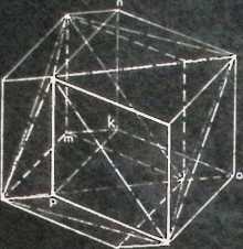
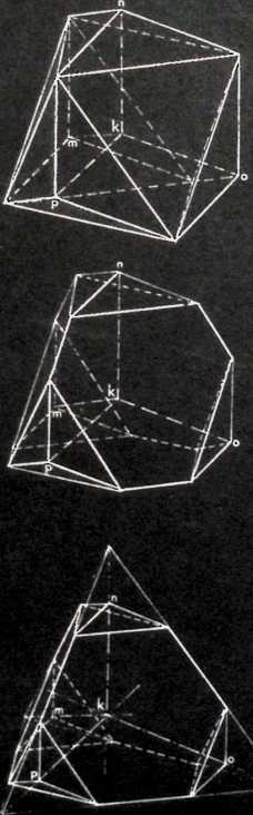
Keith Critchlow has one of the centurys rare conceptual minds. He is continually inspired by the conceptioning of both earliest and latest record. He lauds the work of others while himself pouring forth, in great modesty, whole vista-filling new realizations of natures mathematical structuring. Keith Critchlow has added a new all-space filling snub-tetrahedron to the set of such known polyhedra - the cube, the rhombic dodecahedron, the asymmetric tetrahedron and the asymmetric hexahedron (which latter two I had the good fortune to discover). He is one of the most inspiring young scholar-teachers I have had the privilege to know.
Buckminster Fuller
About the author
Keith Critchlow ARCA was born in 1933, and studied at the Chelsea School of Art. St Martin s School of Art and the Royal College of Art Currently he is Lecturer in the Art and History Department and the Department of Structures at the Architectural Association School.
London. For some years he has also been teaching at the Royal College of Art, the Slade School of Fine Art and at many other art schools, and he was for a period a visiting lecturer at Kumasi University, Ghana. He was awarded a Shell International Research Scholarship in post doctorate mathematics (1967-68). also a Royal Institute of British Architects grant for research in space structures (1968 69)
About this book
This book offers fresh and imaginative insight into the area where mathematics and the arts meet. It can also be used as a practical tool by the architect, designer or scientist who has to deal with such problems as space defining, distribution patterns, space-filling properties, packing and stacking, economy grids and communication linkages.
The author provides a systematic analysis of those space-defining geometries that are relevant to solving design problems and understanding the ordered division of space He develops this thesis from the point of view of the ’experimental mathematician - a term coined to describe one aspect of the work of Buckminster Fuller By means of full-page illustrations, diagrams and charts he presents those mathematical facts and formulae, many of them not previously published, which bear on the definition and understanding of space The material, which can be used in models and projects is accompanied by an explanatory text and precise numerical values
with 45 full-page drawings,
10 photographs. 4 illustrated appendices
Thames and Hudson
30 Bloomsbury Street London WC1
¶ eBook Formats
Chuang Tzu. ch. xvii (4th century sc). ↩︎
LA. Govinda. The Psychological Attitudes of Early Buddhist Philosophy (Rider. London. 1961). ↩︎
Lao Tzu. Tao Teh Ching, ch. ii. trans. Dr J.C. H. Wu (St Johns University Press. Brooklyn. New York. 1961). ↩︎
E. L. Schatzman. The Structure of the Universe, p. 209 (Hutchinson. London: World University Library). ↩︎
J.G. Bennett. The Dramatic Universe (Hodder & Stoughton. London). ↩︎
E. L. Schatzman. The Structure of the Universe, p. 201 (Hutchinson. London: World University Library). ↩︎
We do not avoid the fact that the tetrahedron so traced is a particular one with three straight and three curved edges, and two flat and two double curved surfaces. For convenience we bring the whole into its most economic expression without changing its topological nature. ↩︎
An observation from atomic physics: if we take the simplest and nuclear electron shell of all atoms, the S subshell, we find that the probability distribution (or the time average of electron charge density) is independent of direction in space and varies only in distance from the nucleus The distribution is therefore symmetrically spherical in form. ↩︎
-in the lower drawing, each as a proportion of the unit edge of the contained figures. ↩︎
En-Syn Geometry Chart 1944. See John McHale. R. Buckminster Fuller, p. 38 (Prentice Hall. New York). ↩︎
On geodesics: The essential aim of general relativity is to link the geometrical properties of space with the distribution of matter in space. In relativity the shortest distance between any two points is the path which would be followed by a ray of light, so that light rays in space always follow geodesics. (E. L. Schatzman. The Nature of the Universe, p. 201). ↩︎