Artifacts of R Buckminster Fuller
Volume Four: The Geodesic Revolution, Part 2, 1960-1983
James Ward (Editor)
Garland Publishing, Inc. | New York and London
ISBN:
ISBN-10: 0-8240-5085-1
Updated: 2024-07-14 19:18
Copyright © 1984
All rights reserved. No part of this book may be reproduced or transmitted in any form or by any means, electronic or mechanical, including photocopying, recording, or by any information storage and retrieval system, without permission in writing from the Publisher.
ENCODED IN THE UNITED STATES OF AMERICA
¶ Contents
■ fflffifeS;
itM
ns and 'Drawing;
7-feffi;
zHrKSS
»fili«P»»s«
!- ■;
?ww.
'IO
‘7,‘j-i
■rr; 4 * ,*’ >T’ - <tc‘. A: ‘ S <> r'j ;J
:-t-.‘_~*
siiSO
________________
This volume is submitted
FOR REVIEW
Date of
Publication
Please forward two clippings of any review that is published to:
Vance Allen Promotion Division
GARLAND PUBLISHING, INC.
136 Madison Avenue
New York, NY 10016
(212) 686-7492
THE ARTIFACTS OF
R. BUCKMINSTER FULLER
A Comprehensive Collection of His Designs and Drawings in Four Volumes
Edited with descriptions by James Ward
A Garland Series
Contents of the Set
Volume One. The Dymaxion Experiment, 1926–1943
Volume Two. Dymaxion Deployment, 1927–1946
Volume Three. The Geodesic Revolution, Part 1, 1947–1959
Volume Four. The Geodesic Revolution, Part 2, 1960–1983
THE ARTIFACTS OF
R. BUCKMINSTER FULLER
Volume Four: The Geodesic Revolution Part 2, 1960–1983
Edited with descriptions by James Ward with an Appendix by D. L. Richter
Garland Publishing, Inc.
New York and London 1985
ABOUT THE EDITOR
Janies Ward is presently a visiting professor at Trinity College. Hartford, Connecticut. He studied engineering as an undergraduate and received his Ph.D. in the history of art from the Institute of Fine Arts of New York University. His dissertation was on Le Corbusiers villa. Les Terrasses. He has published articles on early modern architecture in Europe and has compiled a directory of New York architects before World War II.
Copyright © 1984 by the Estate of R. Buckminster Fuller ‘‘Working with Buckminster Fuller.’’ by Don Richter, © 1984 by Don Richter
Library of Congress Cataloging in Publication Data
Fuller. R. Buckminster (Richard Buckminster), 1895–
The artifacts of R. Buckminster Fuller.
Includes bibliographies.
Contents: v. 1. The Dymaxion experiment, 1926–1943—
v. 2. Dymaxion deployment, 1927–1946—v. 3. The geodesic revolution, part 1, 1947–1959—[etc. ]
1. Engineering design—Collected works. 2. Fuller.
R. Buckminster (Richard Buckminster). 1895- —
collected works. I. Ward, James. II. Title.
TA174.F86 1984 620'.00425 84-21039
ISBN 0-8240-5085-1 (v. 4: alk paper)
Book design by Jonathan Billing
The volumes in (his series have been printed on acid-free 250-year-life paper.
Printed in the Uniled States of America
Proposed Geodesic Dome for a Shopping Center in Montreal, Canada, 1960 1
Yomiuri Golf Club Geodesic Dome, Tokyo, 1961–1963 3
Octet Truss Patent, 5/30/61 29
Residence of R. Buckminster Fuller and Anne Hewlett Fuller, Carbondale, Illinois, 1960 32
Tensegrity Patent, 11/13/62 36
Submarisle (Undersea Island) Patent, 3/12/63 40
Tensegrity Chandelier for Princess Margaret, 1964 43
Fuller & Sadao, 1964–1983 44
Tensegrity Dome for Israel, Fuller & Sadao, 1964 46
Aspension Geodesic Structures Patent, 7/7/64 48
Geodesic Dwellings for General Electric, Fuller & Sadao, 1964 51
Geodesic Domes for the Brookhaven National Laboratory, Fuller & Sadao, 1964 54
United States Pavilion Designed for Expo ’67 (Trabeated Truss), Fuller & Sadao,
1964.
55
Harlem Redesign, New York City, Fuller & Sadao, 1964 61
Fine Arts Gallery of the University of Colorado, Fuller & Sadao, 1965 62
Price and Rutzebeck Dome, Fuller & Sadao,
1965.
64
Monohex Geodesic Structures Patent, 8/31/65 72
Laminar Dome Patent, 8/31/65 76
Octa Spinner Patent Application, 1965 81
Yomiuri Tower, Japan, Fuller & Sadao,
1966.
83
Tensegrity Joint, Fuller & Sadao, 1966 92
United States Pavilion Designed for Expo ’67, Montreal, Canada, Fuller & Sadao with Geometries, Inc., 1966–1967 95
Star Tensegrity Octahedral Truss Patent, 11/28/67 139
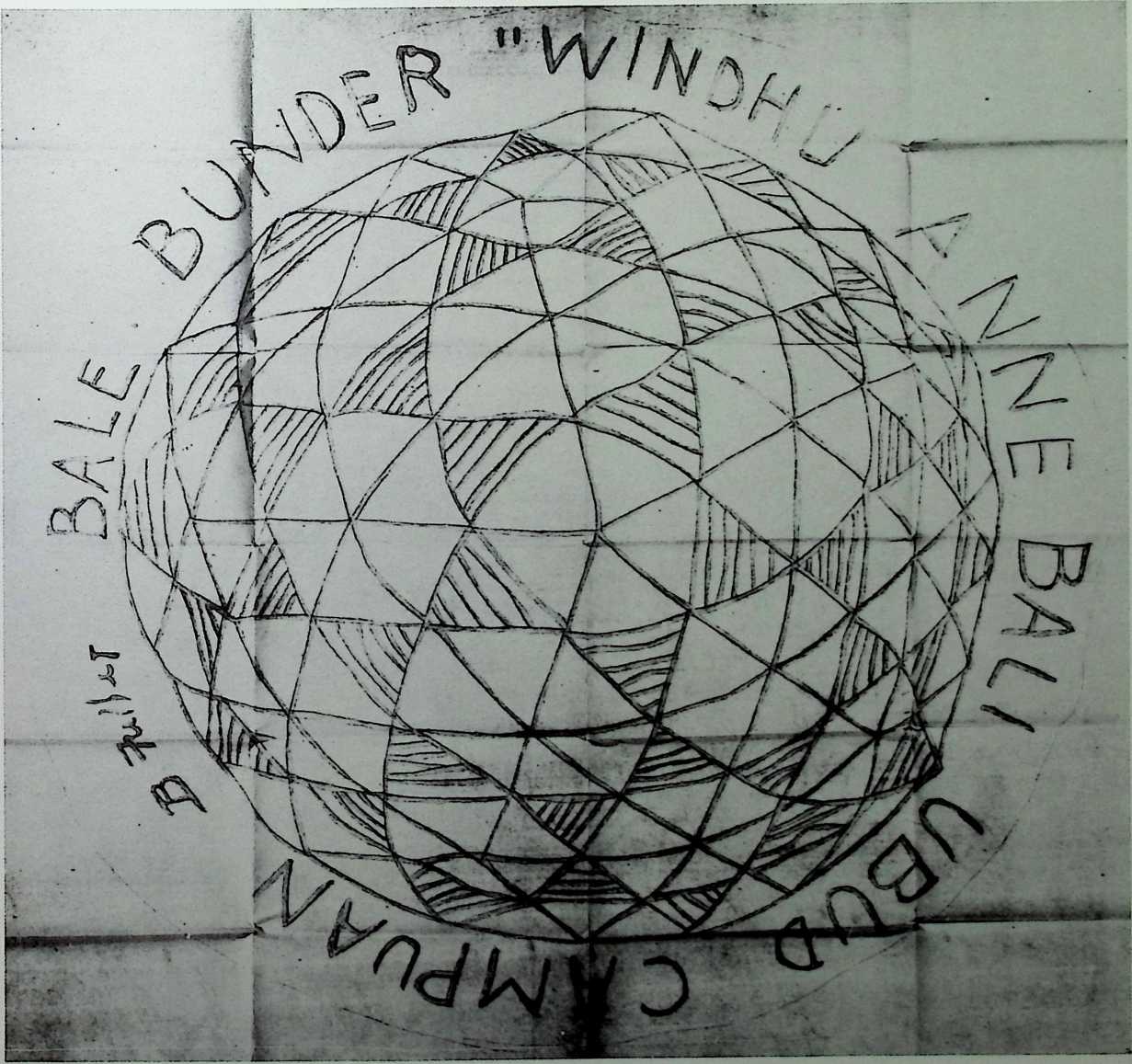
‘‘Bale Bunder Windhu Anne Bali Ubud Campuan’’ Dome, 1967 143
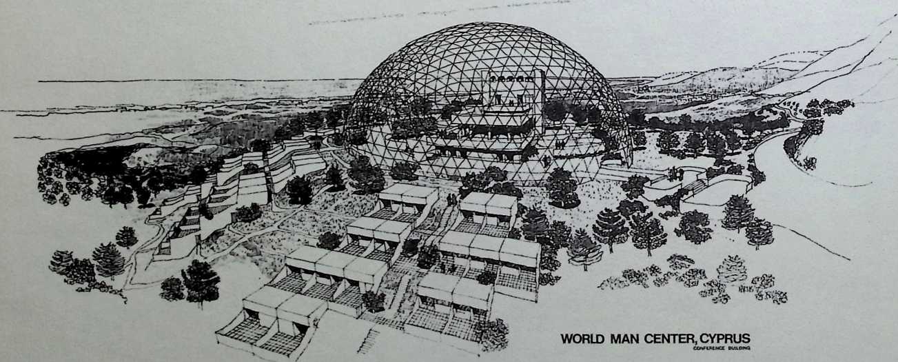
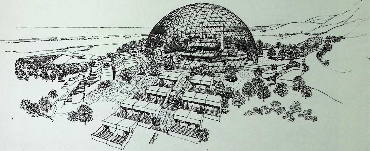
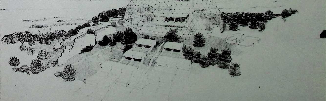
World Man Center Conference Building, Cyprus, Fuller & Sadao, 1967 144
The Cobum Classical Institute, Waterville, Maine, 1968 147
Main Observation Tower, Government of Kuwait, Ministry of Electricity and Water, Fuller & Sadao with Geometries, Inc., 1968 162
Triton City, Triton Foundation, Fuller & Sadao, 1968 175
Piedmont Panorama Center for the South Carolina Tricentennial, 1969–1970 181
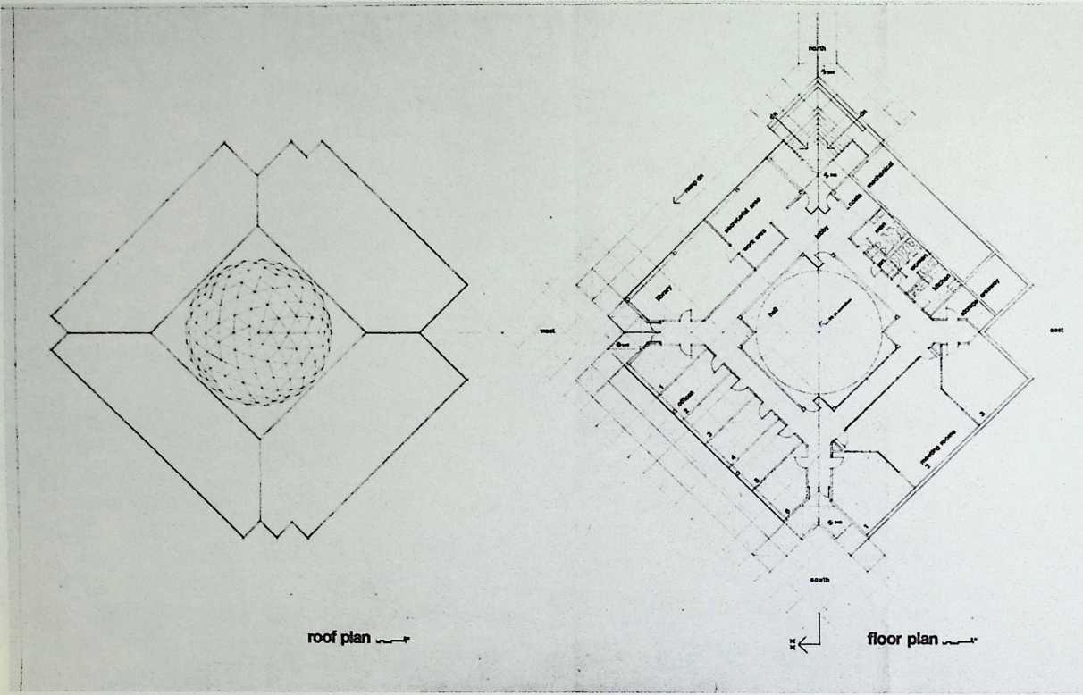
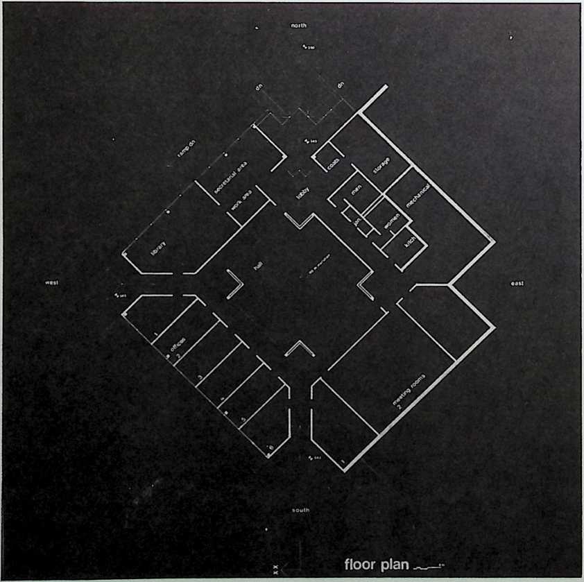
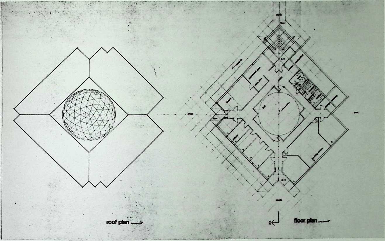
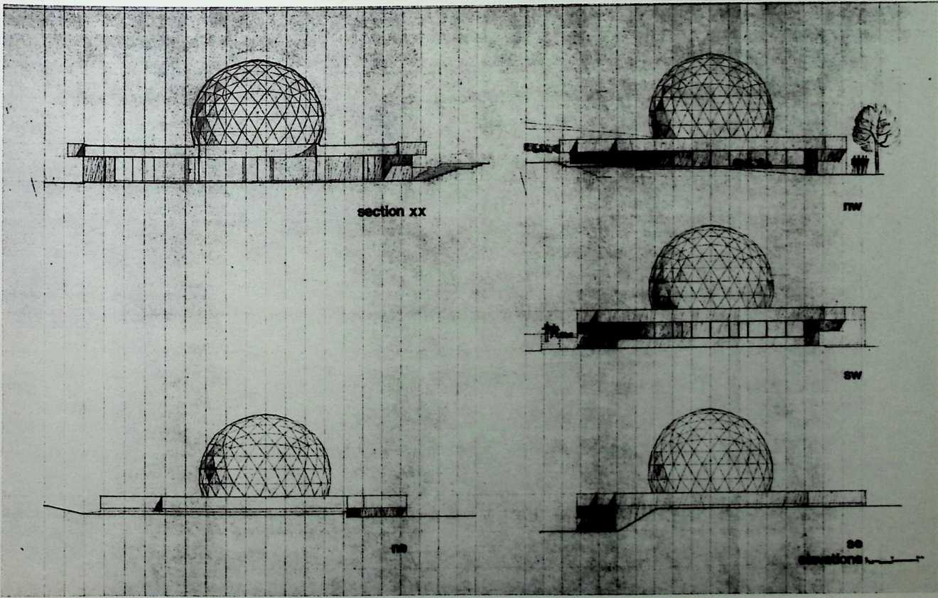
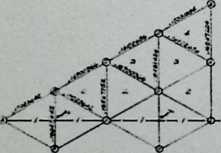
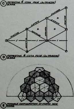
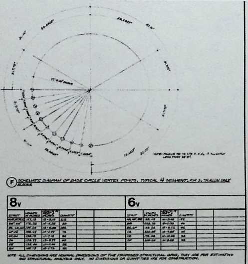
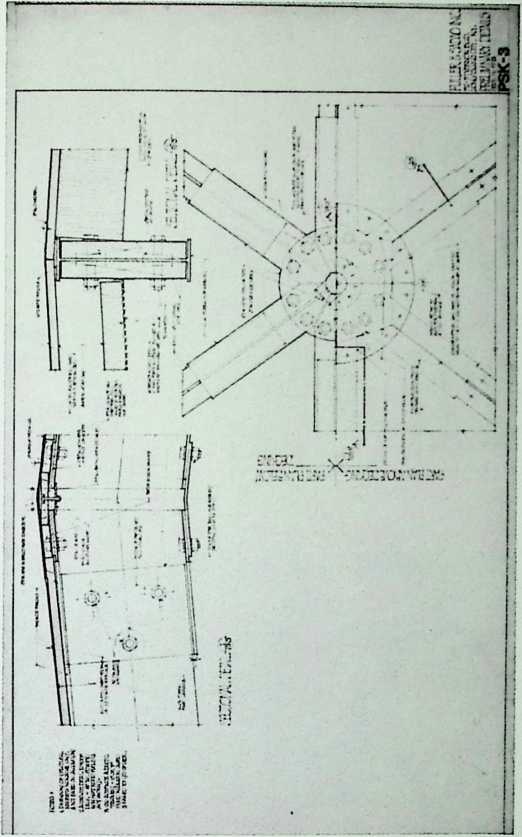
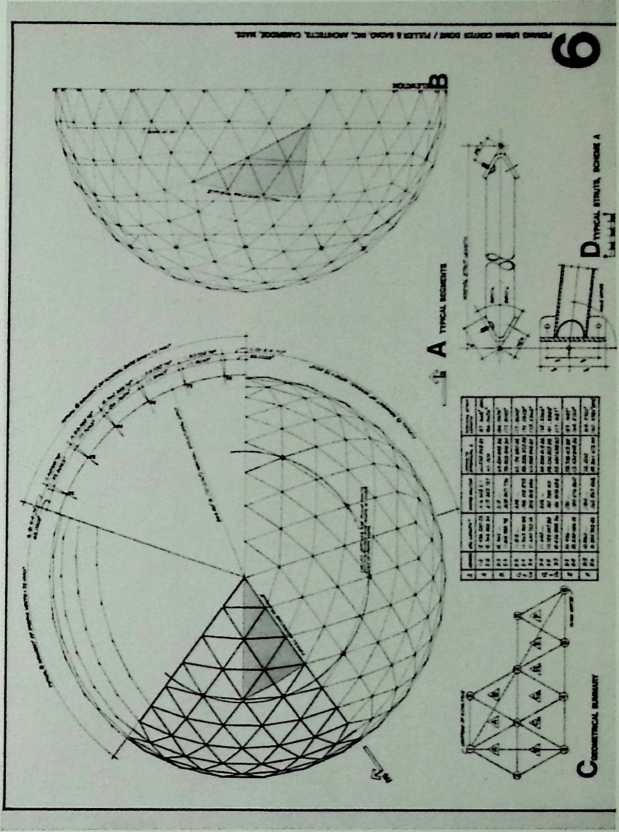
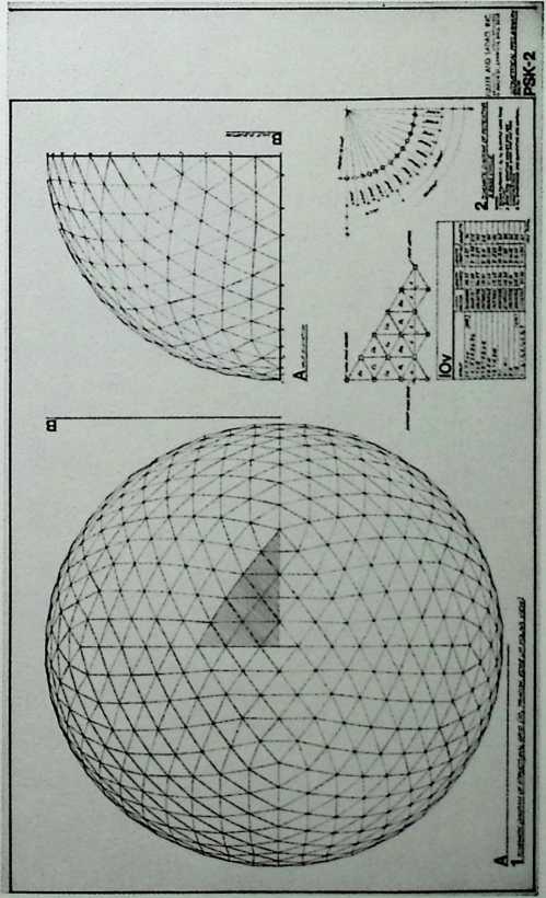
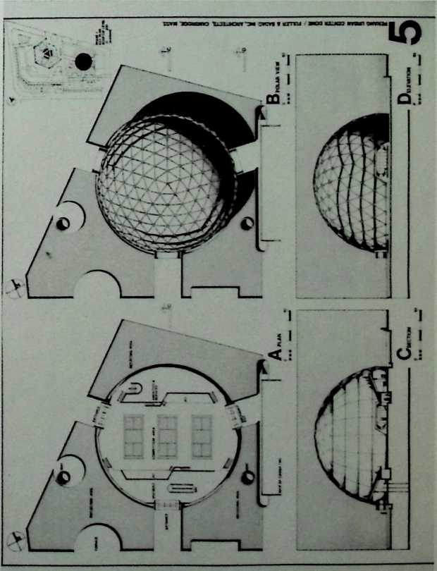
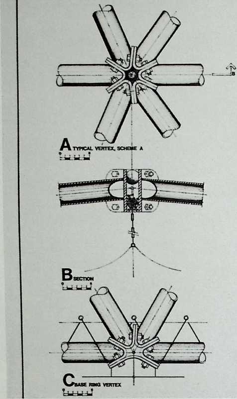
Campus Religious Center, Southern Illinois University, Edwardsville, Fuller & Sadao (Designed by Shoji Sadao and Karlis Grinbergs), 1969 192
Vault for Quincy Market, Boston, Fuller & Sadao, 1969 216
Three Utopian Projects, 1960–1970 217
Cultural Community Center, Kfar Menachem. Kibbutz Kashomer, Hatzair, Israel, Fuller & Sadao, 1970 219
Project Spadina, Toronto, Canada, Fuller & Sadao, 1970 223
Rowing Needles (Watercraft) Patent. 8/18/70 229
Project Pearland, Pearland, Texas. Fuller & Sadao, 1971 233
Bangor-Punta Production Domes, Fuller & Sadao, 1971 235
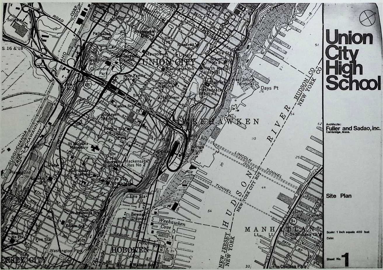
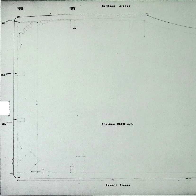
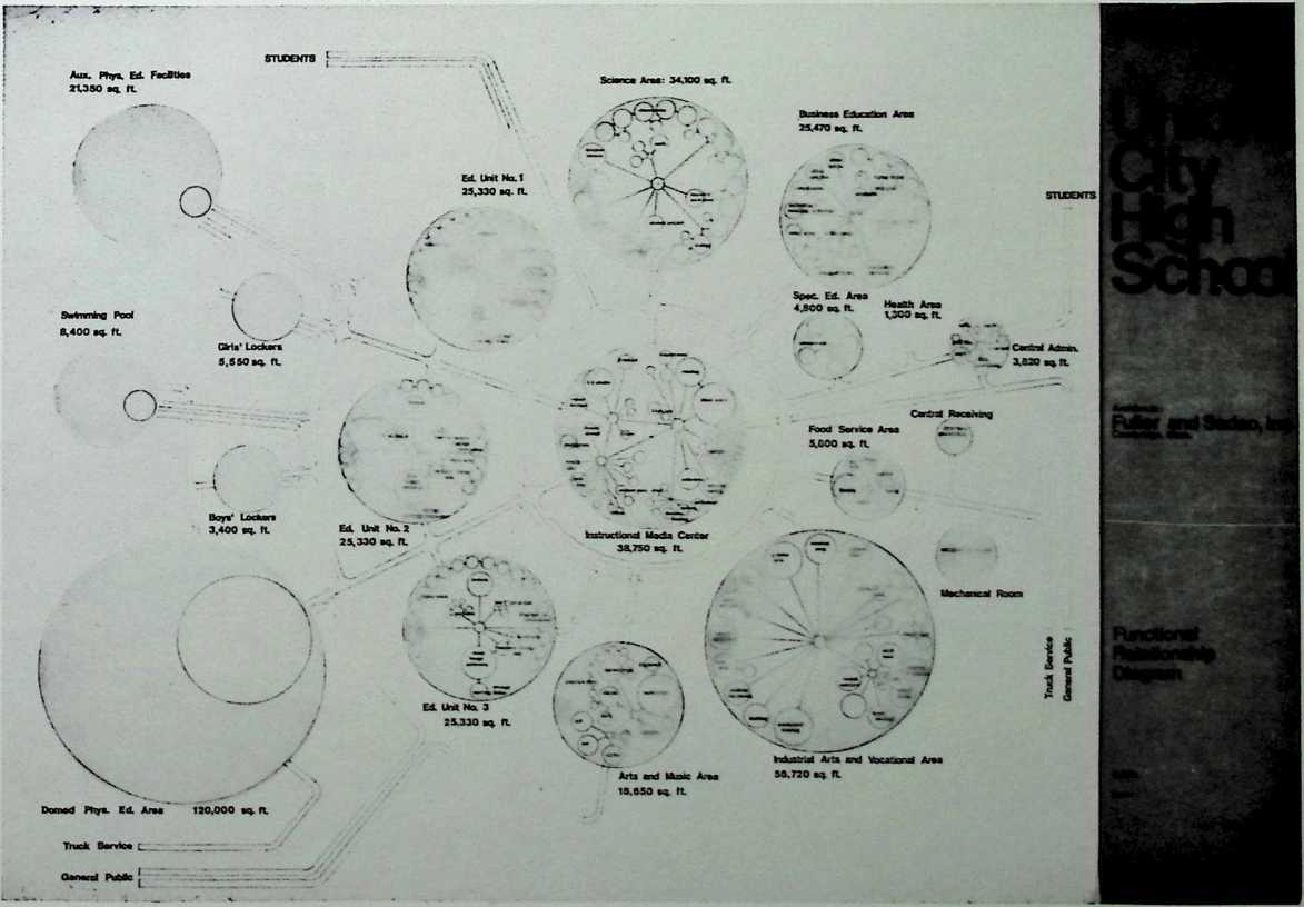
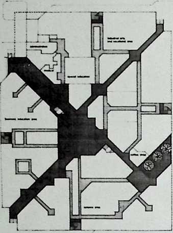
Union City High School. Union City, New Jersey, Fuller & Sadao, 1971 240
Popular Science Dome, Fuller & Sadao. 1972 245
Paperboard Dome, India. Fuller & Sadao, 1972 249
International Airports for India: Palani in New Delhi, Fuller & Sadao. 1972 250
International Airports for India: Santa Cruz in Bombay, Fuller & Sadao, 1972 261
International Airports for India: Meenambakkam in Madras, Fuller & Sadao, 1972 265
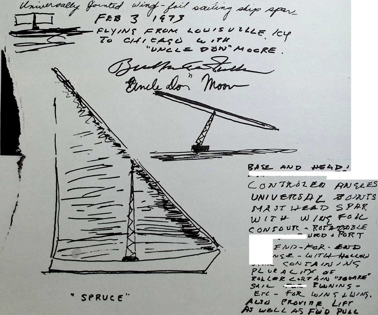
The Spruce (Sailboat), 1973 274
Eastern Connecticut State College Amphitheater, Fuller & Sadao, 1973 275
University of Pennsylvania Art Gallery, Fuller
& Sadao, 1973 277
Old Man River: An Umbrellaed Town Concept for East Saint Louis, Illinois, 1970–1974 279
Old Man River, Sketches, 1970–1971 280
Old Man River, Finished Project, 1974 285
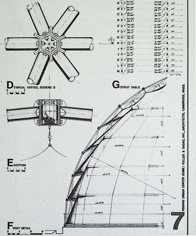
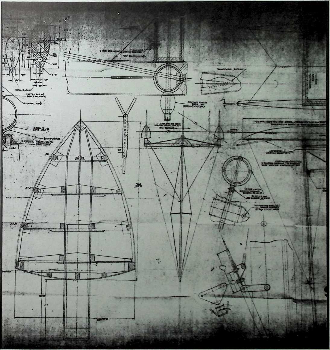
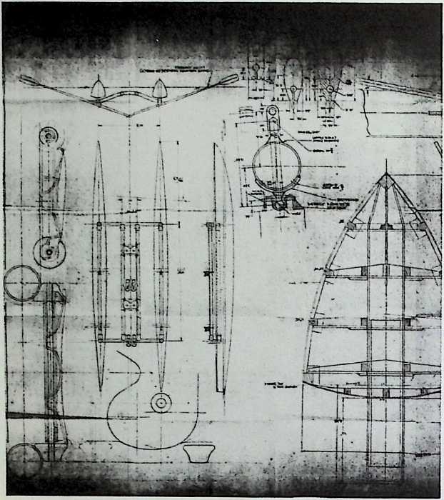
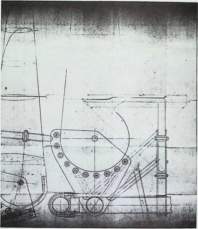
Penang Urban Center, Penang, Malaysia, Fuller & Sadao, 1974 288
The Sailor Cat (Catamaran), 1974 291
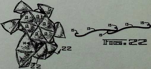
Floatable Breakwater Patent, 2/4/75 295
Nonsymmetrical Tensegrity Patent, 2/18/75 297
Allegra Dome, 1975 300
Delaware Flower Show Dome, Fuller & Sadao, 1975 302
Twindome 20/30, Fuller & Sadao, 1975 304
The Now House, 1975–1976 305
Forty-four-Foot-Diameter Duplex Dome, Fuller & Sadao, 1976 317
Thirty-four-Foot-Diameter Single-Family
Dome, Fuller & Sadao, 1976 318
Designs for a Proposed Geoscope for Montreal, Canada, 1976 319
Pine Cone Dome, 1977 321
Temporary Dome for the Perry Nuclear Power Plant, Perry, Ohio, 1977 326
East River Park Amphitheater, New York
City, Fuller & Sadao, 1977–1979 336
Space Theater for Dance and Noguchi Sets, Designed by Isamu Noguchi, 1978 345
Icosahedron Tower for the Crossing of the Cathedral Church of St. John the Divine (Unexecuted), New York City, Fuller & Sadao, 1978 346
NJ’s Datsun Dome for Wichita, Kansas, Fuller & Sadao, 1978 348
Archaeological Shelter Project at the Excavation Site of Ban Chiang, Thailand, Fuller & Sadao, 1978–1979 353
Earth Resources Observatory, the Unisphere, Sioux Falls, South Dakota, Fuller & Sadao (Consultants) and The Spitznagel Partners, Inc. (Architects and Engineers), 1979 360
Floating Breakwater Patent, 1/30/79 363
Restoration of the United States Pavilion, Expo ’67, Fuller & Sadao, 1979 366
Tensegrity Module Patent, 6/17/80 369
Jitterbug Sculpture, University of Akron, Fuller & Sadao, 1979–1980 372
Lotus Dome, Penang, Malaysia, Fuller & Sadao, 1980 374
4V Parallel Sheet-Metal Dome, Fuller & Sadao, 1980 377
Hanging Storage Shelf Unit Patent, 3/22/83 378
Appendix: Working with Buckminster Fuller, by Don L. Richter 381
¶ List of Figures
¶ List of Tables
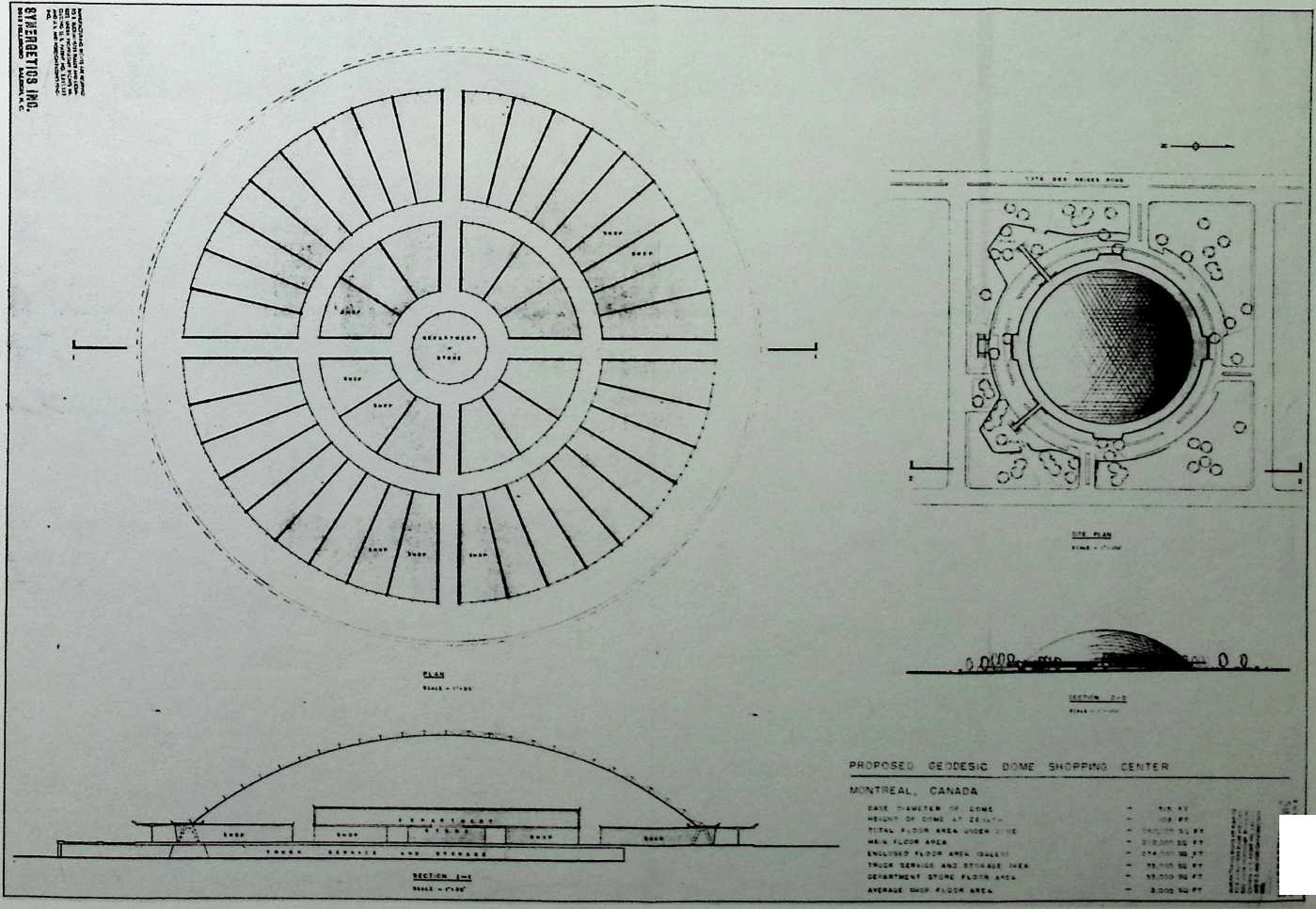
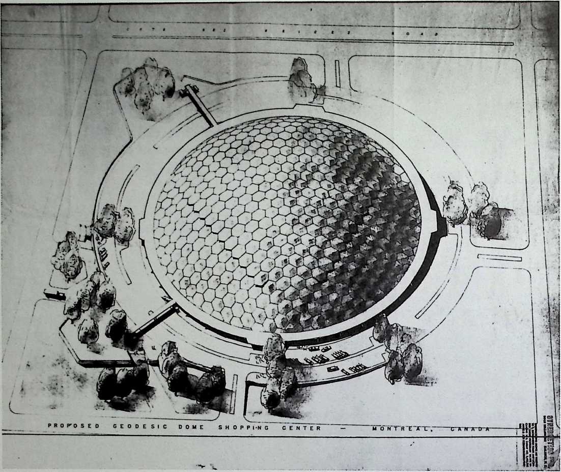
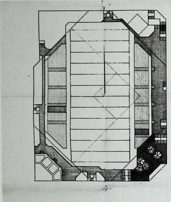
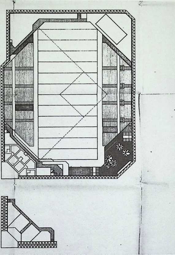
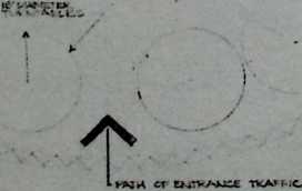
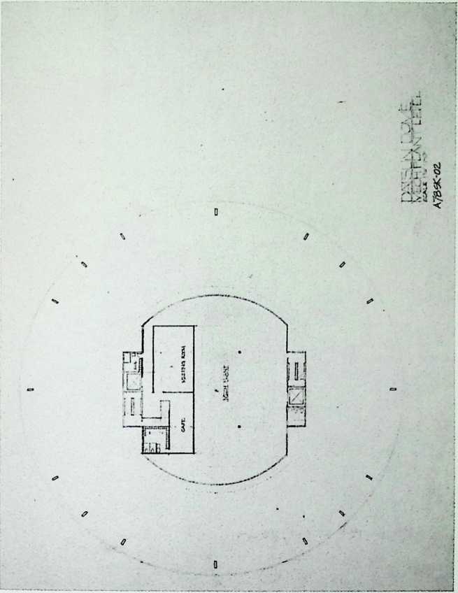
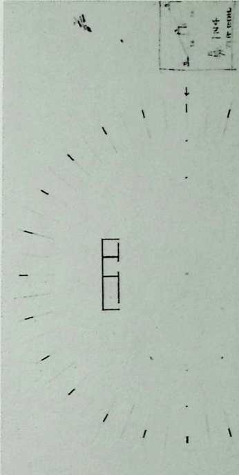
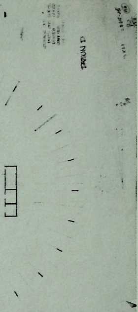
¶ Chapter 1 Proposed Geodesic Dome for a Shopping Center in Montreal, Canada 1960
The plan of this dome is its most interesting feature. Two concentric rings of forty-eight shops were to be reached via two concentric arcades and two cruciform arcades. The dome’s center is occupied by a department store that spreads out to cover the inner ring of shops. Merchandise enters and leaves the complex through the basement storage area.
UHMETI\1,
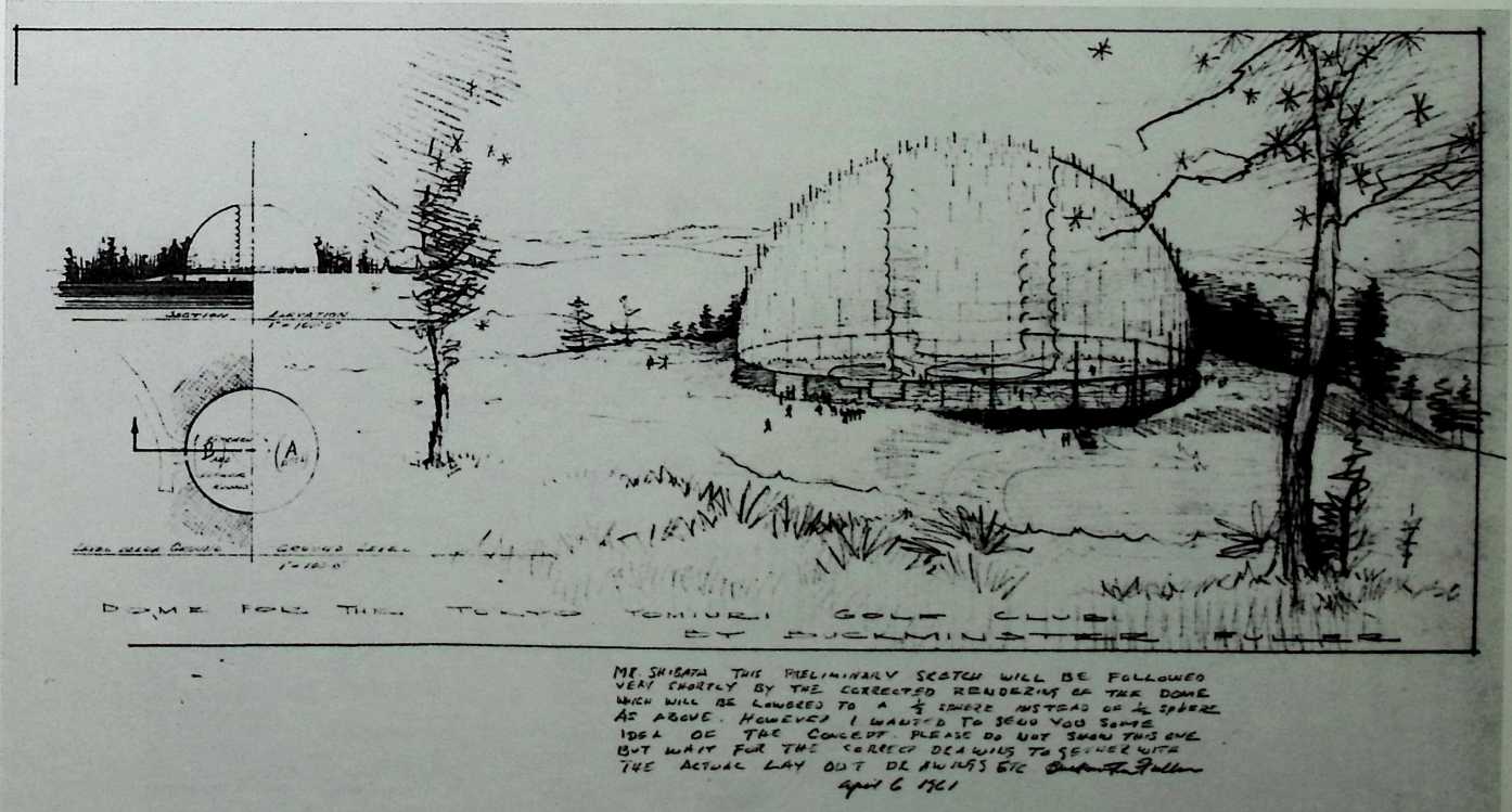
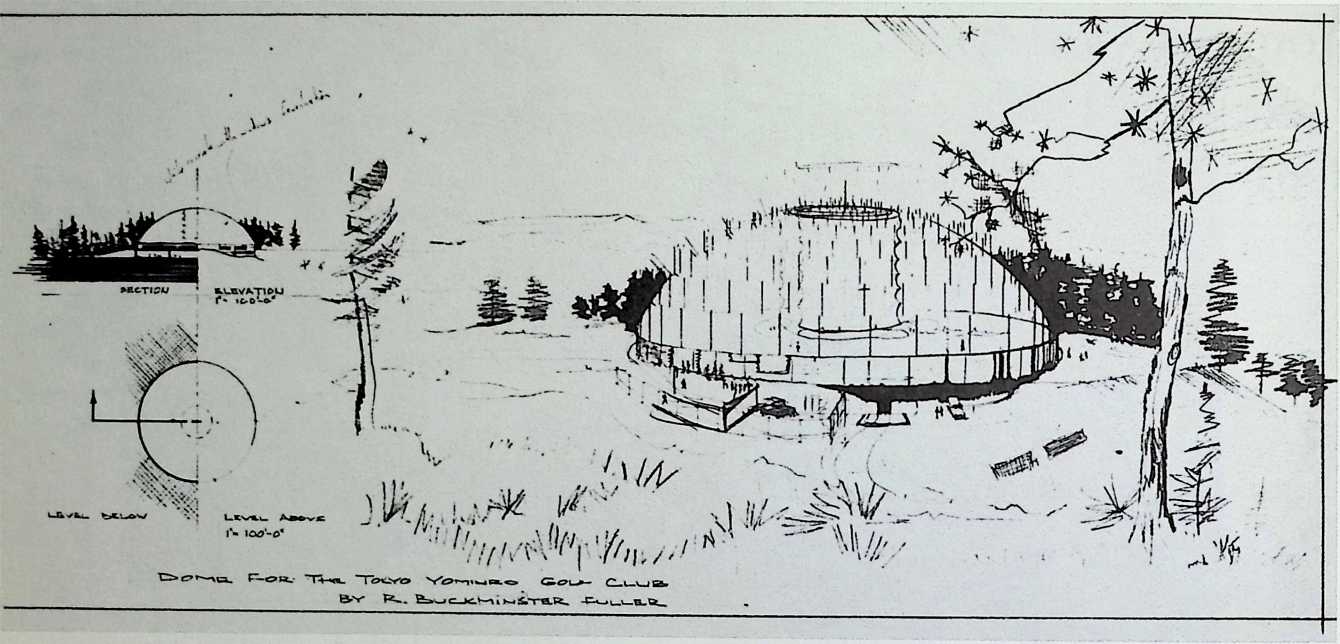
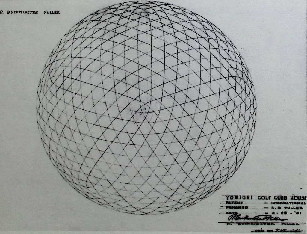
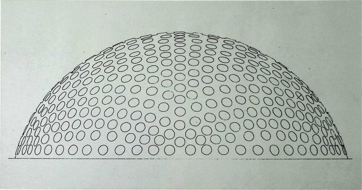
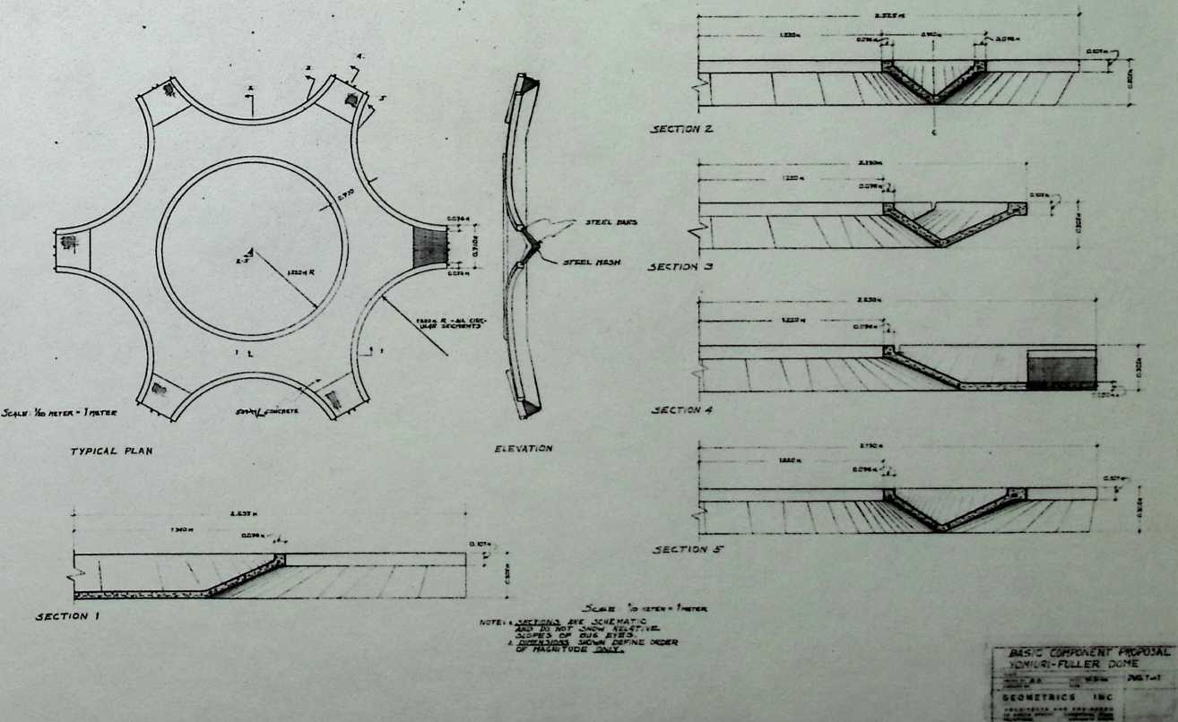
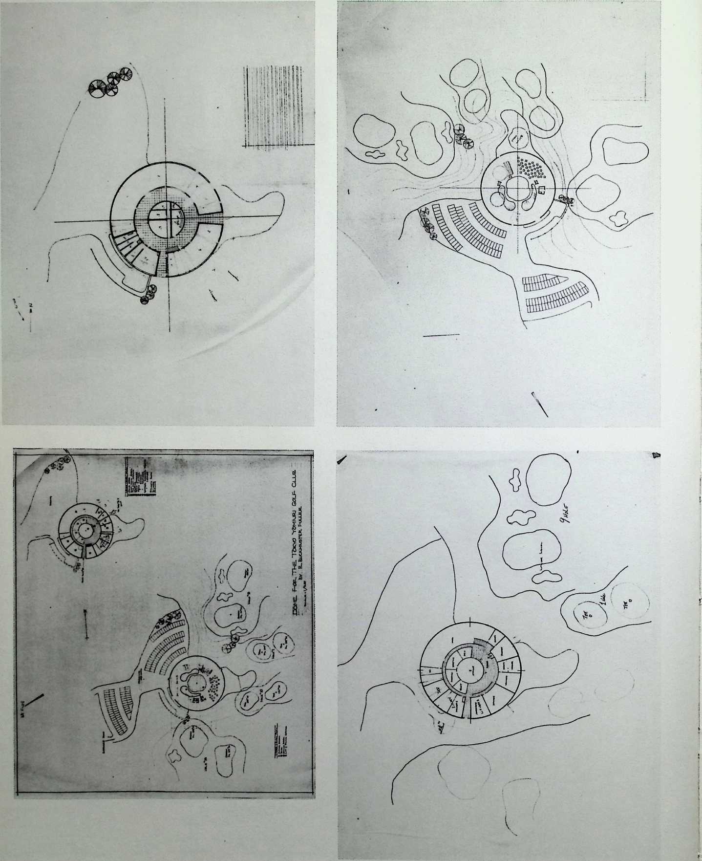
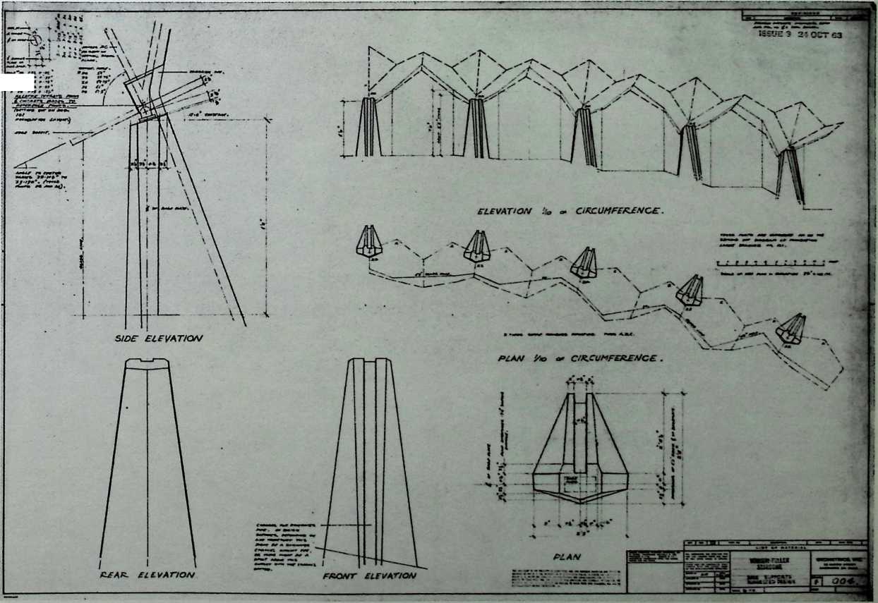
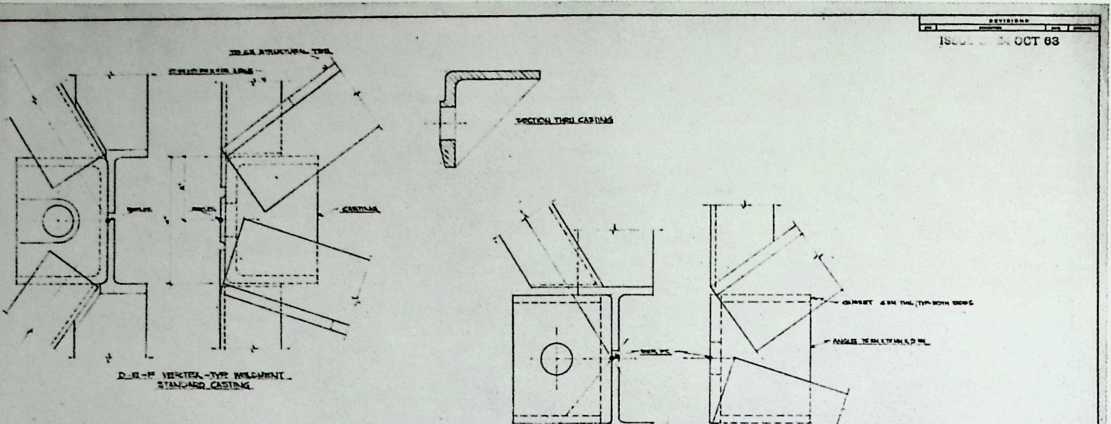
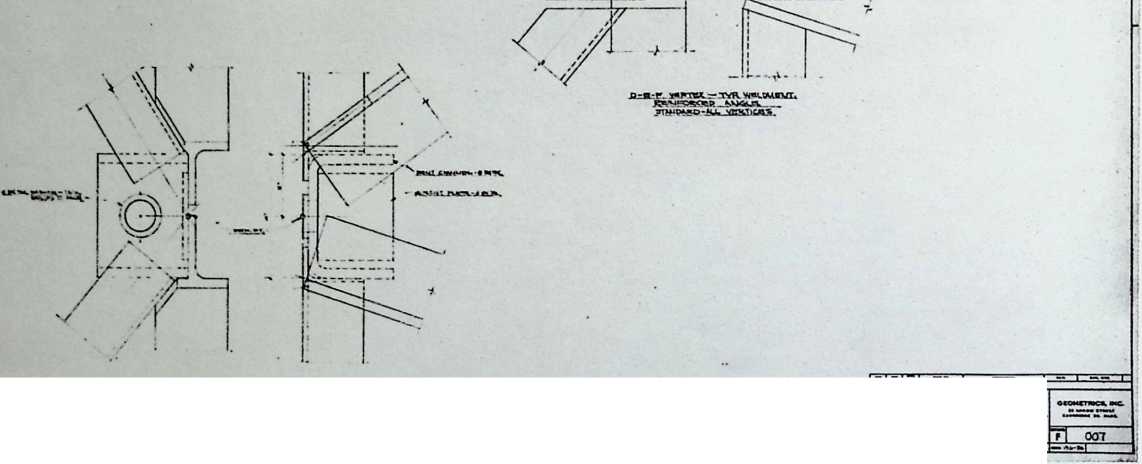
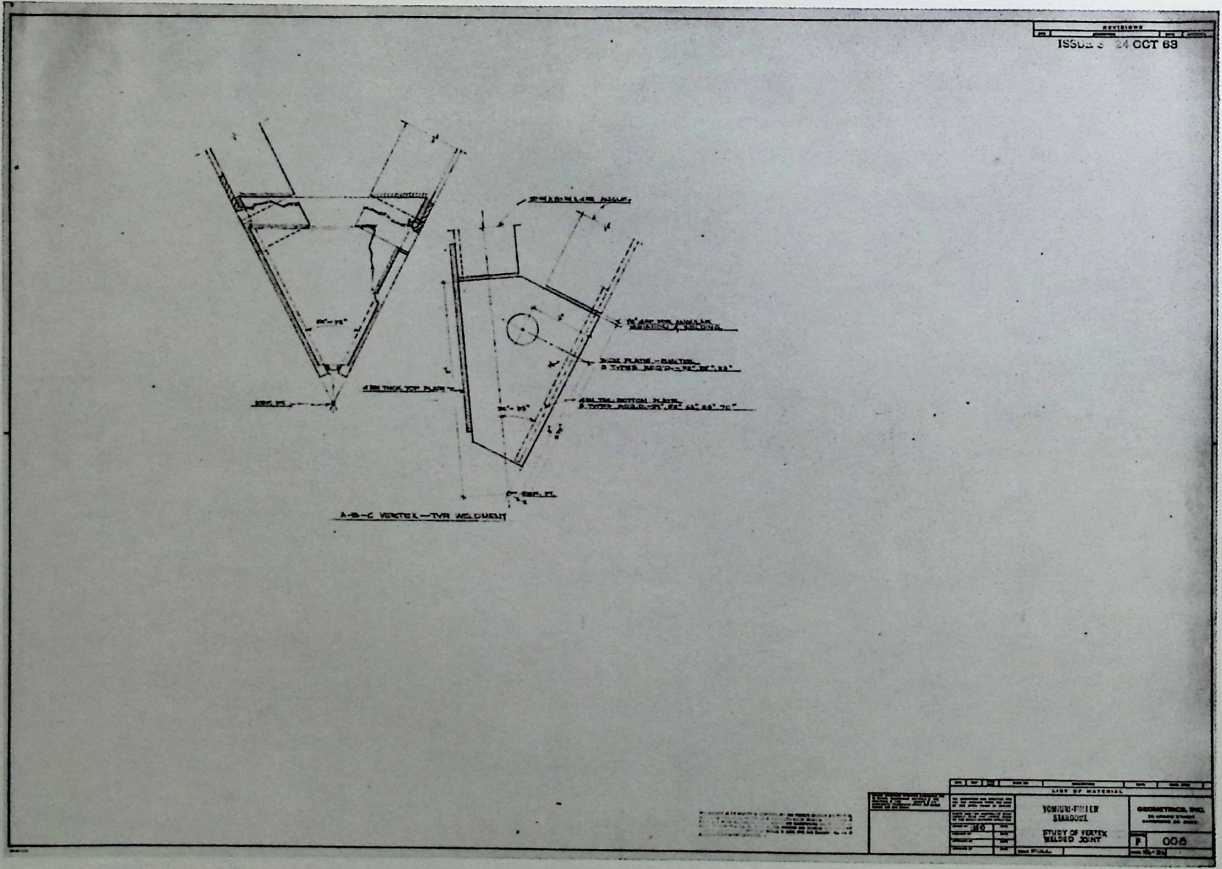
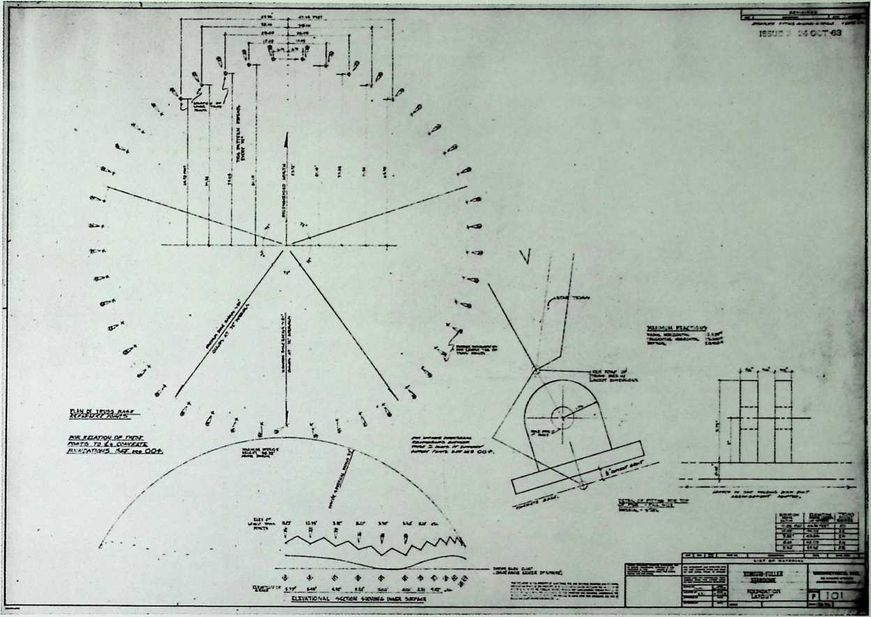
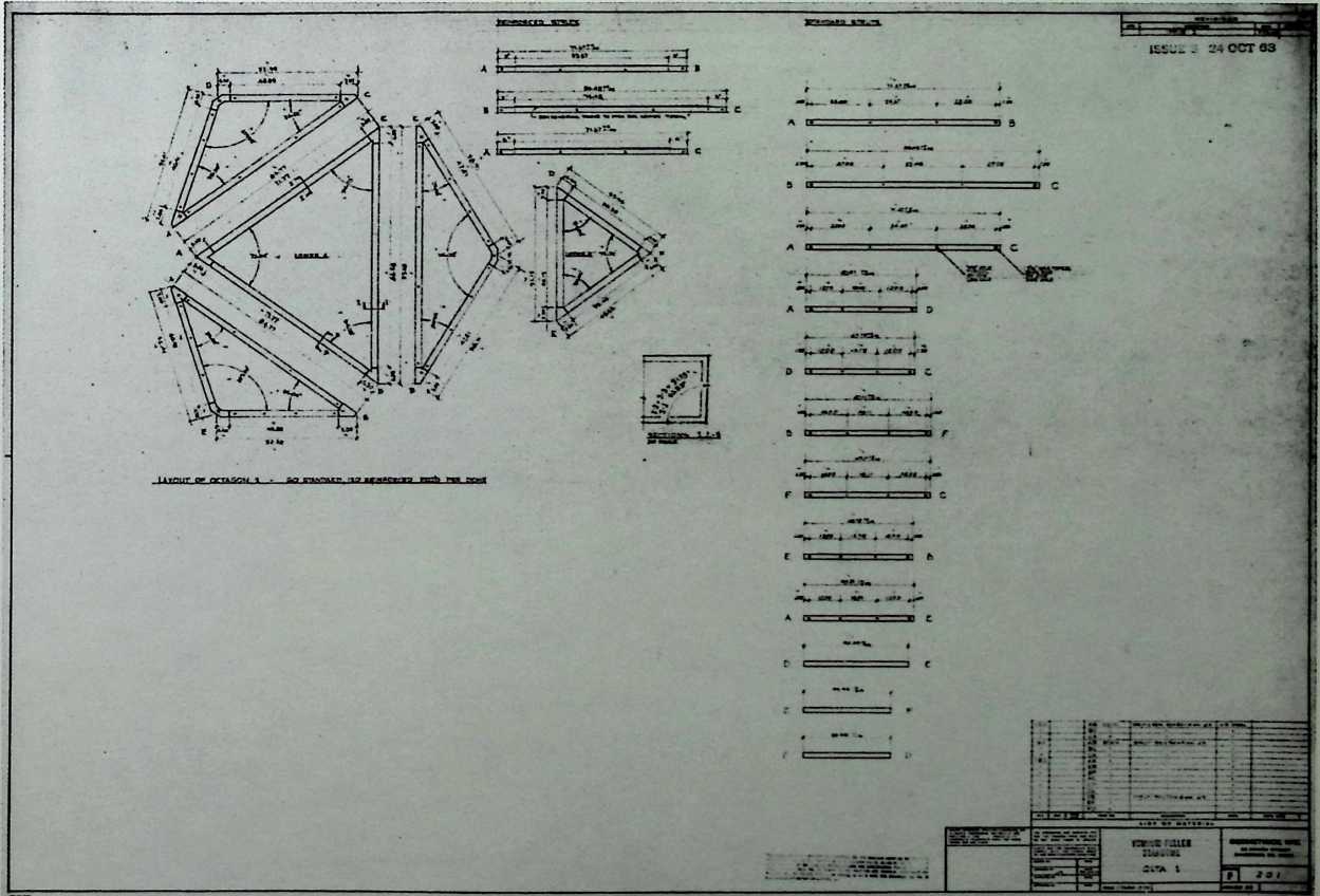
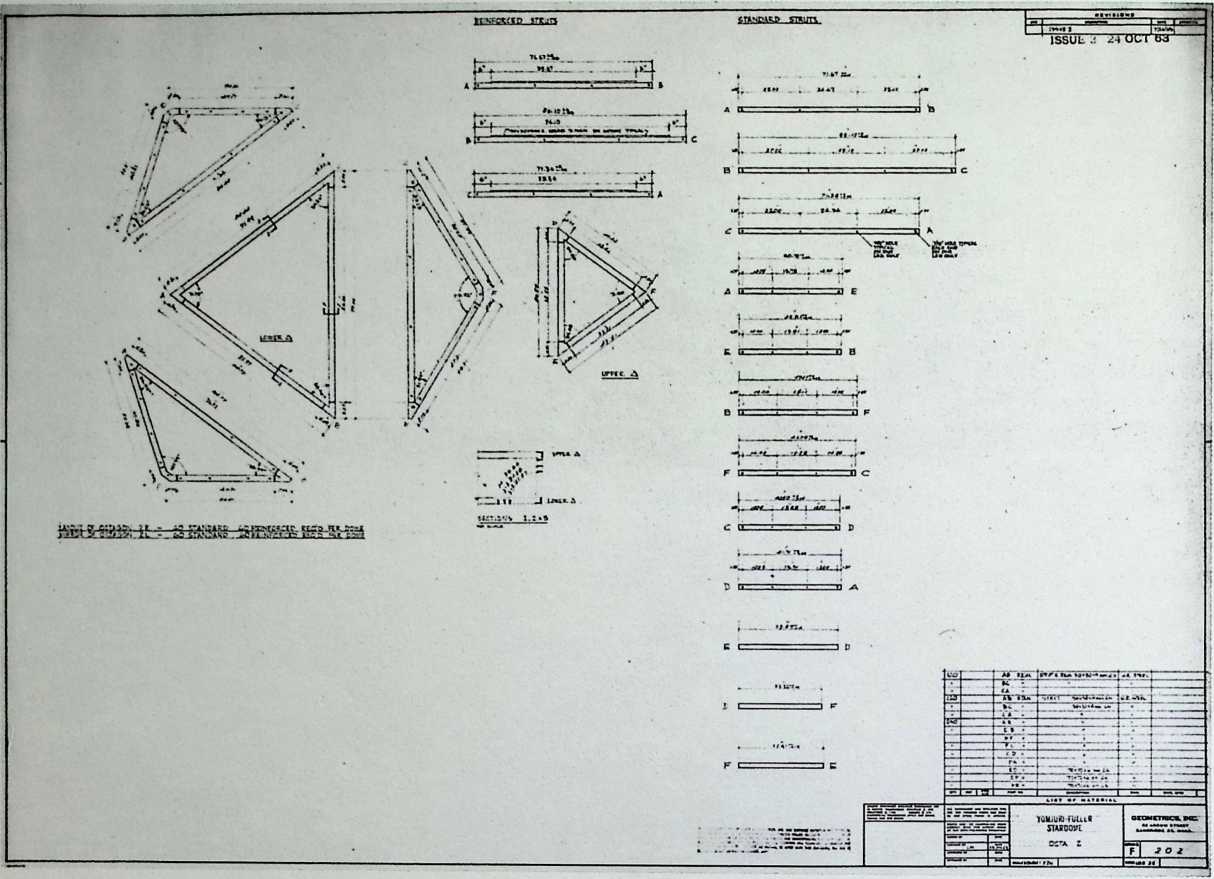
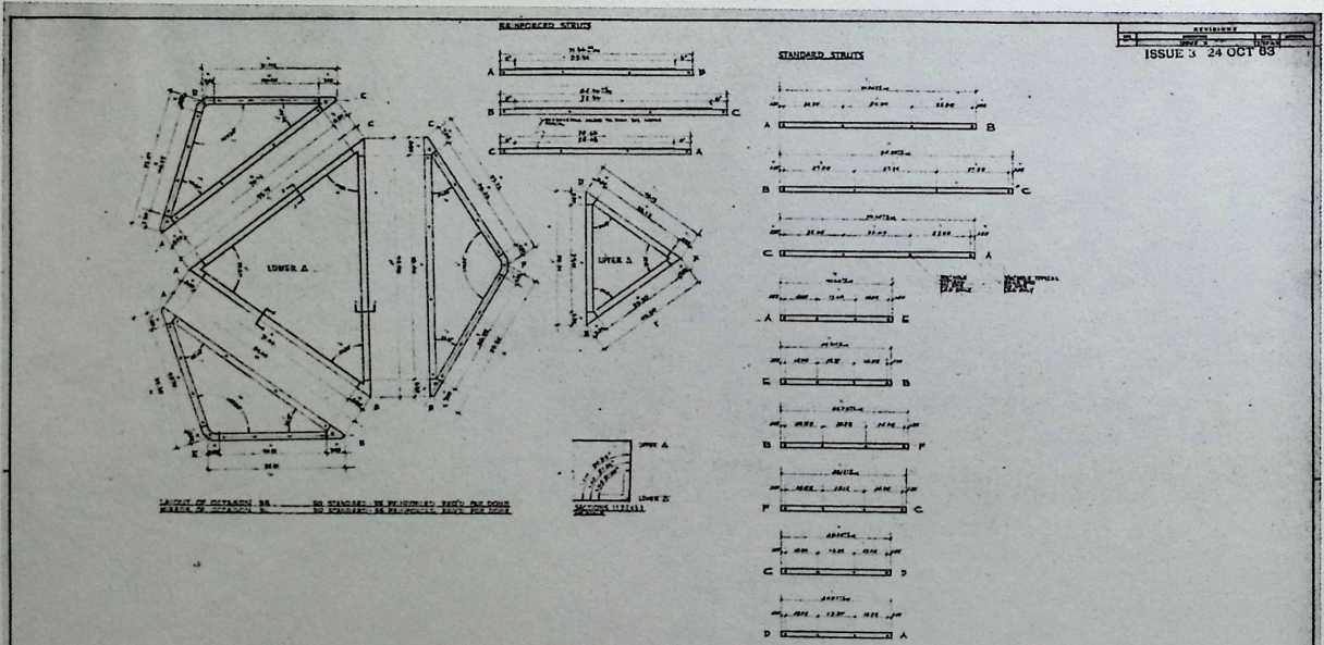
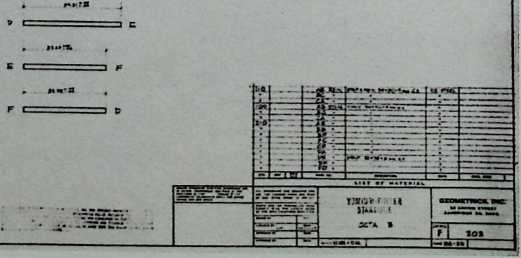
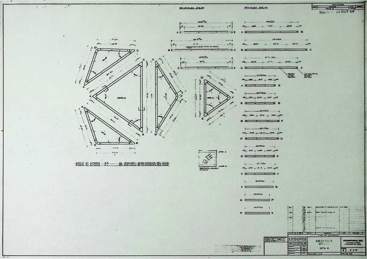
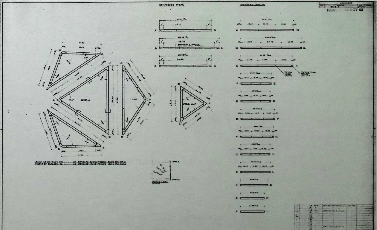
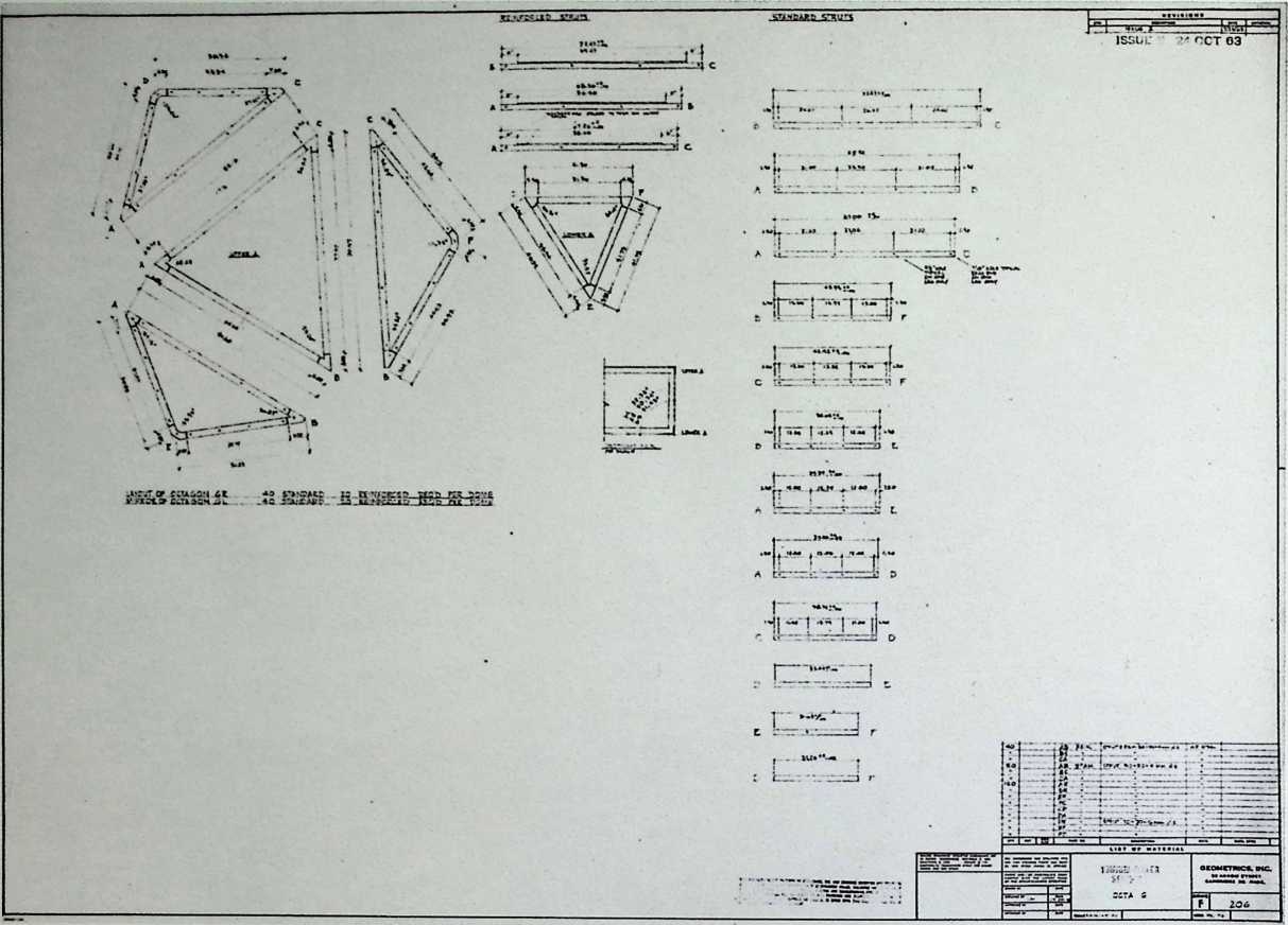
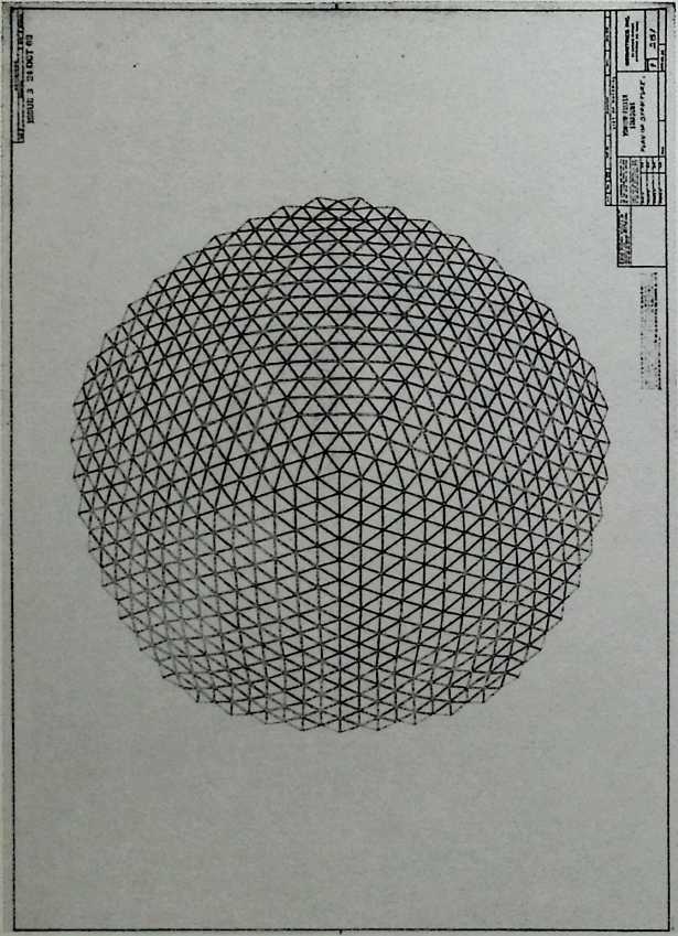
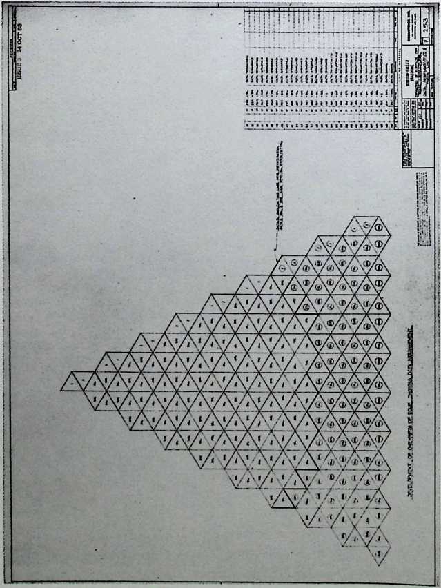
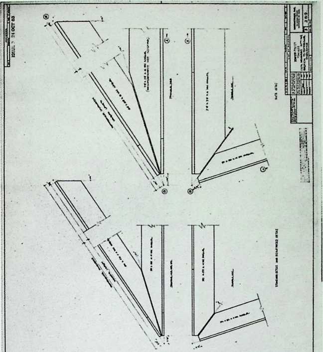
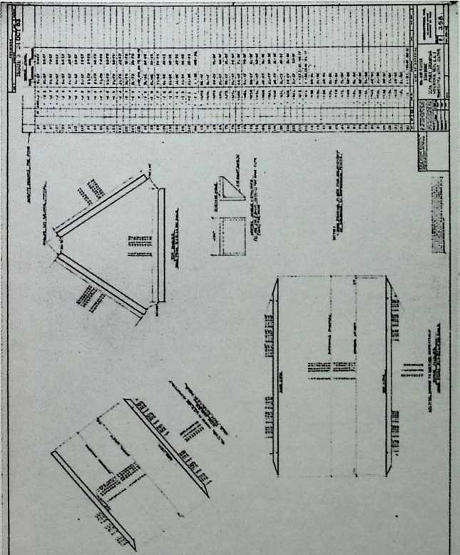
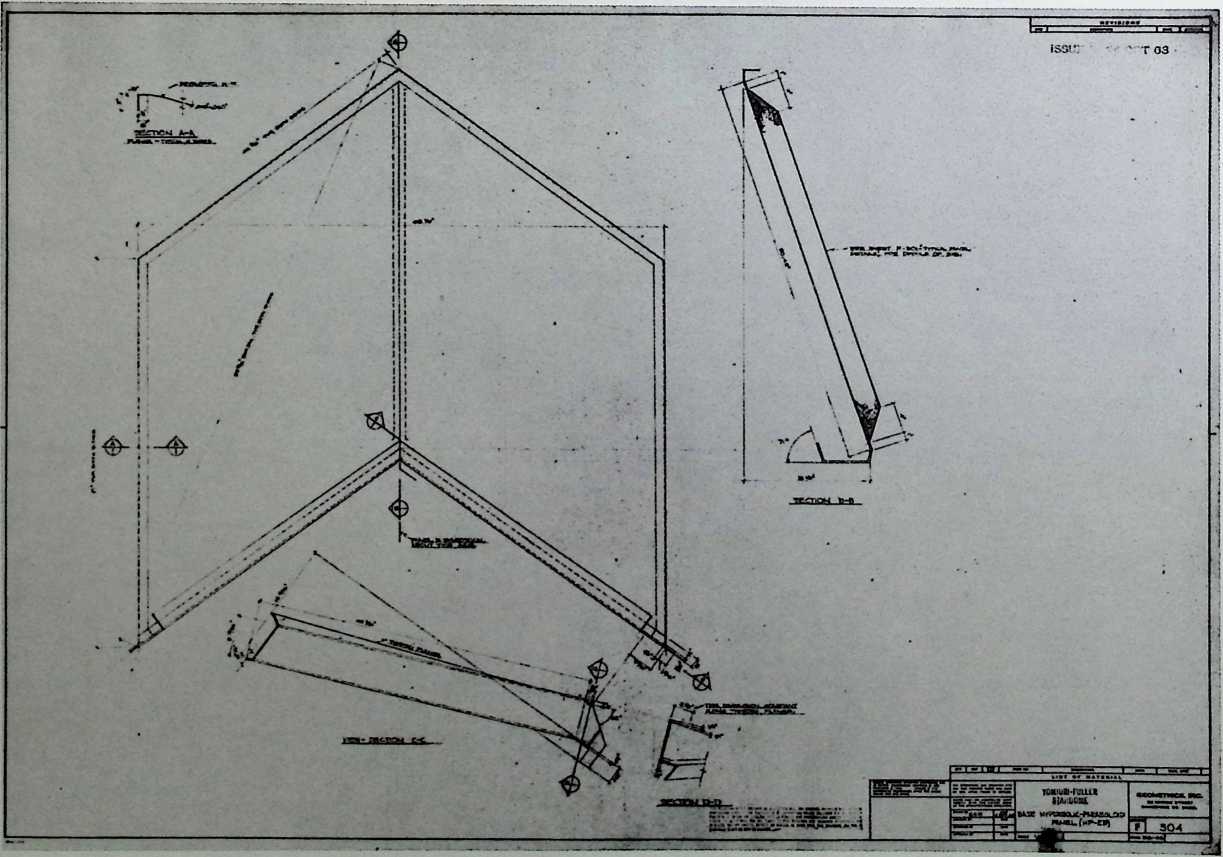
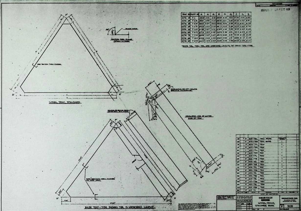
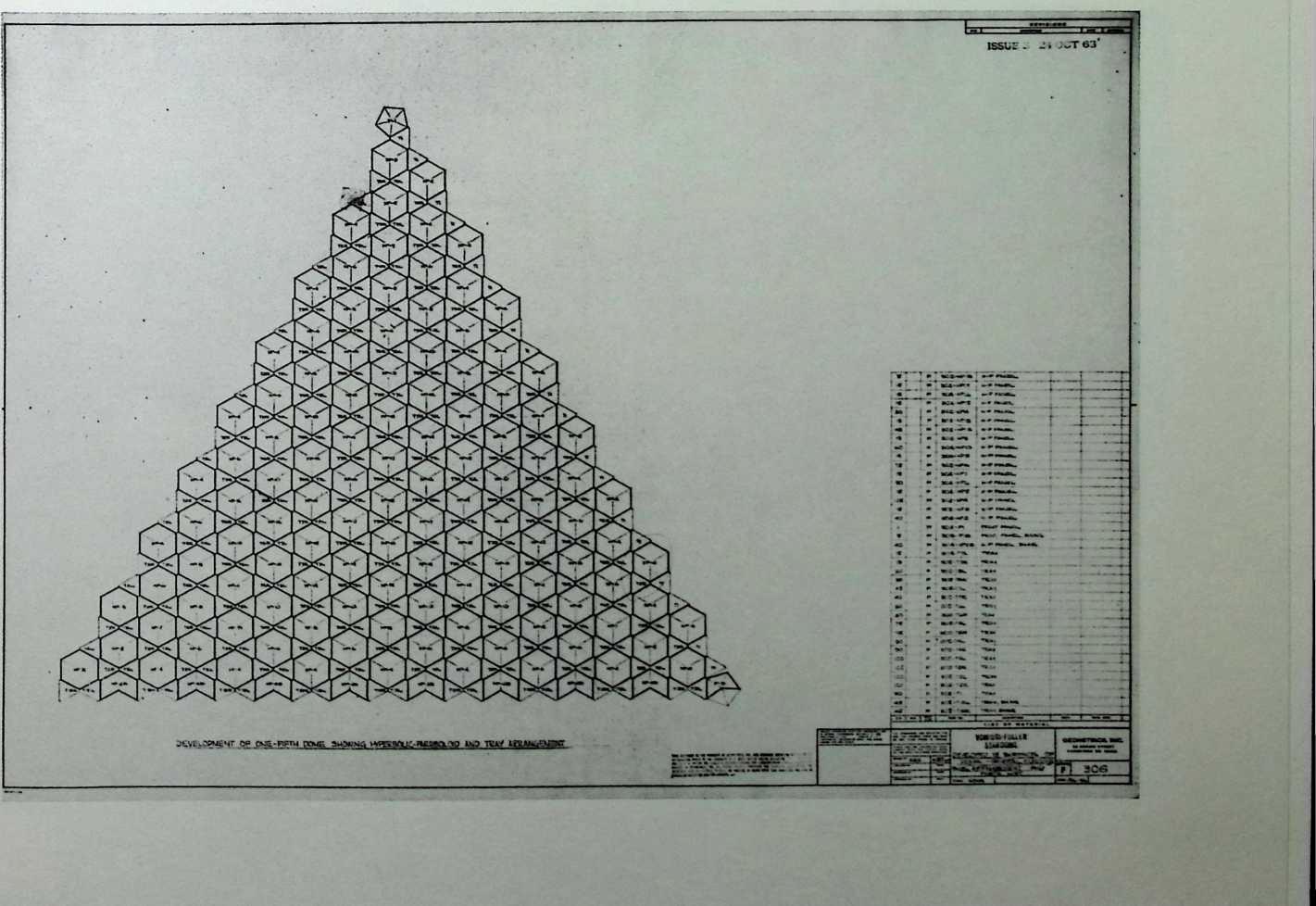
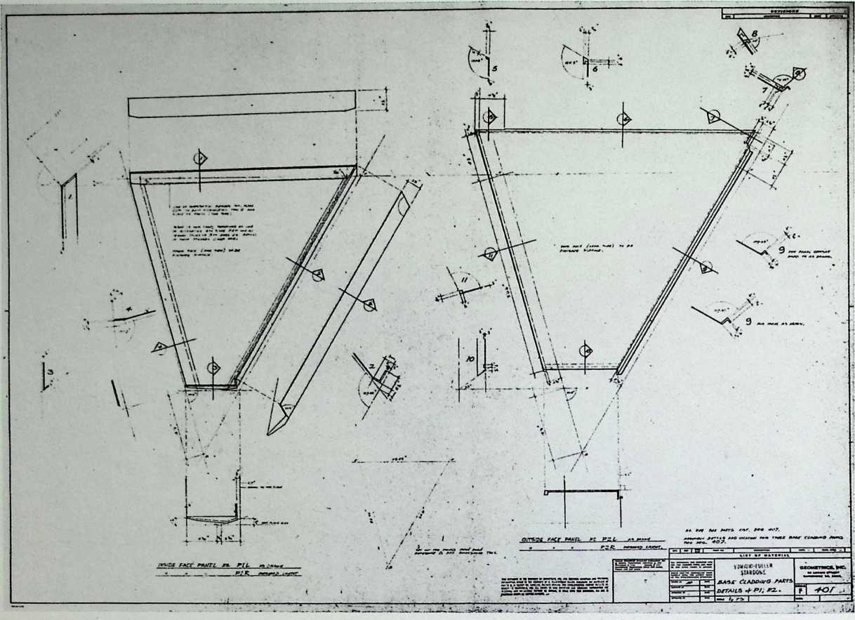
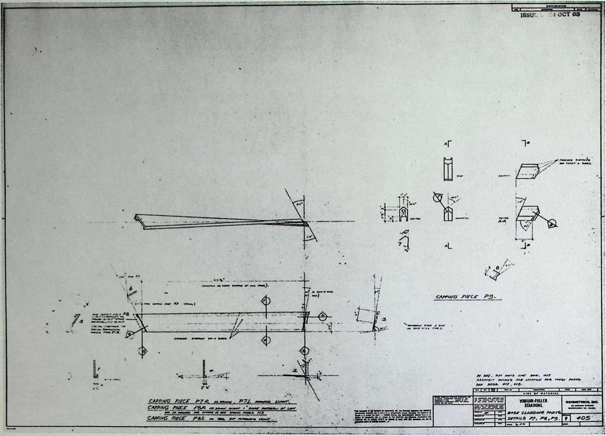
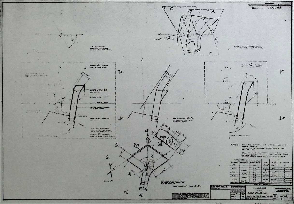
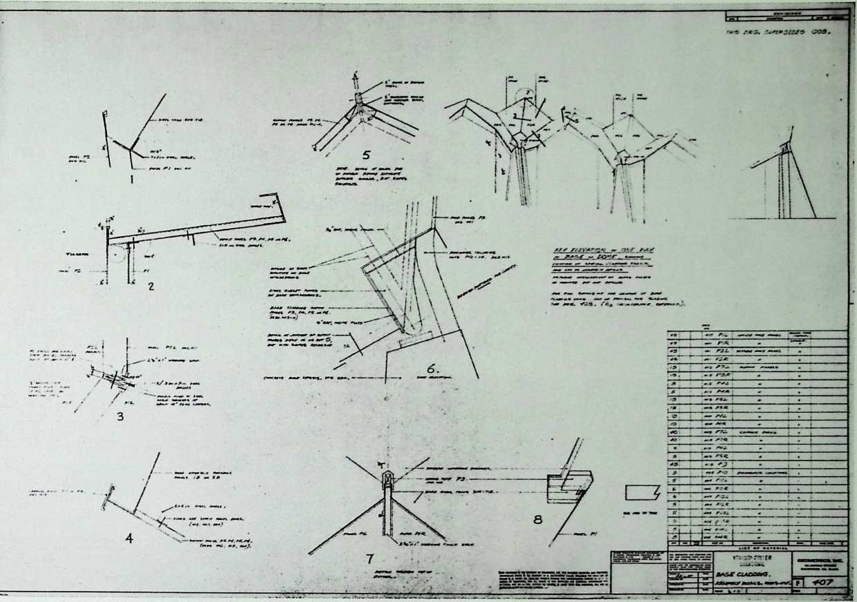
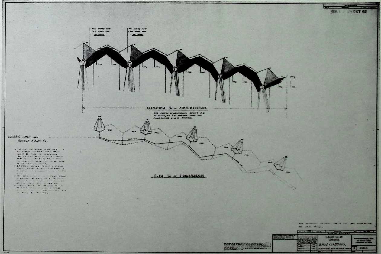
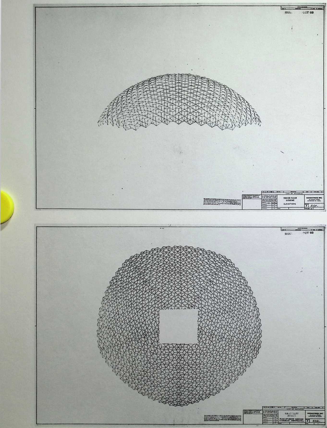
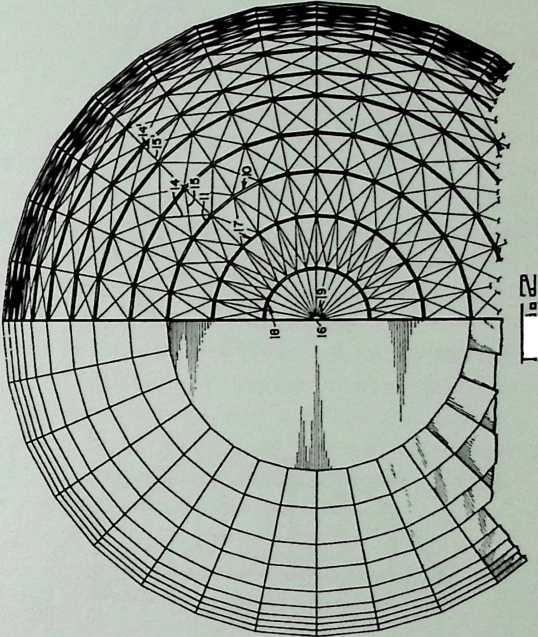
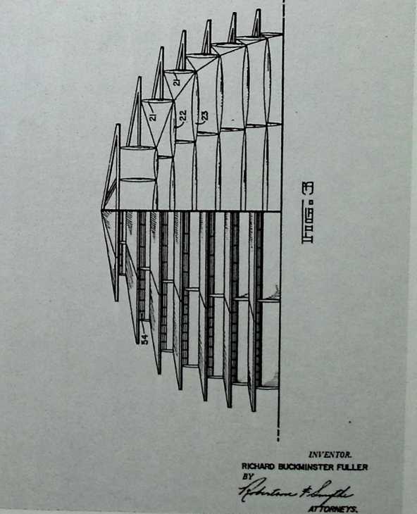
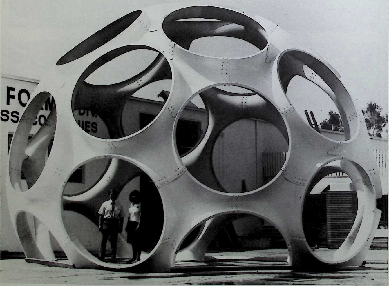
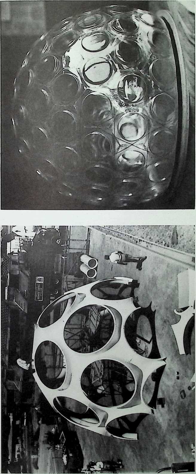
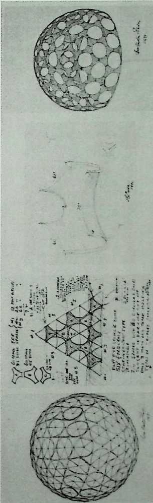
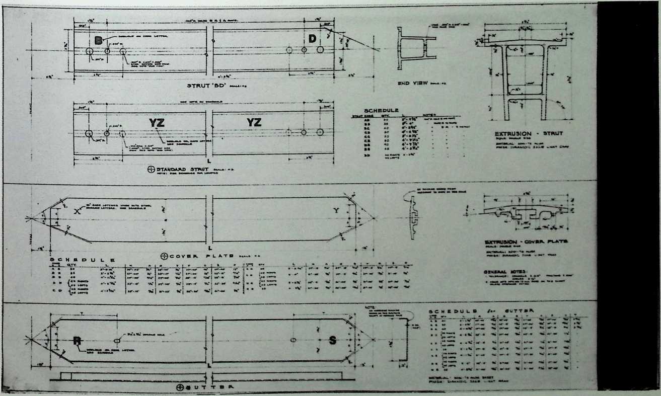
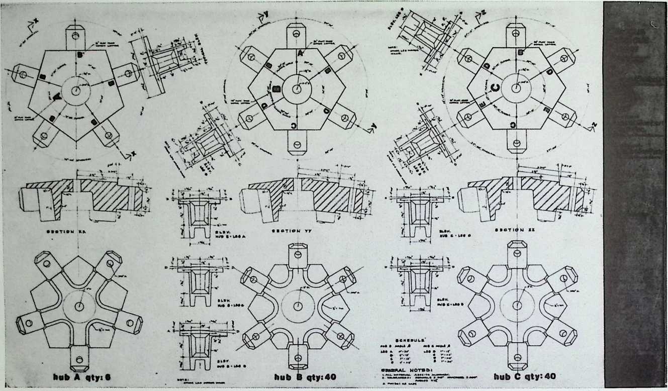
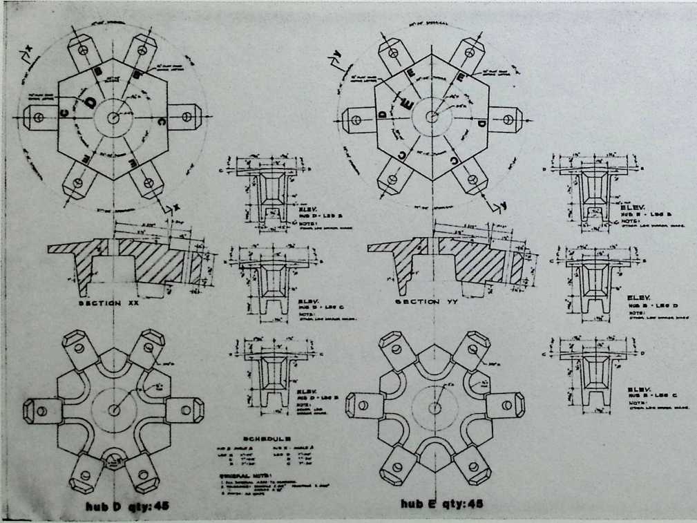
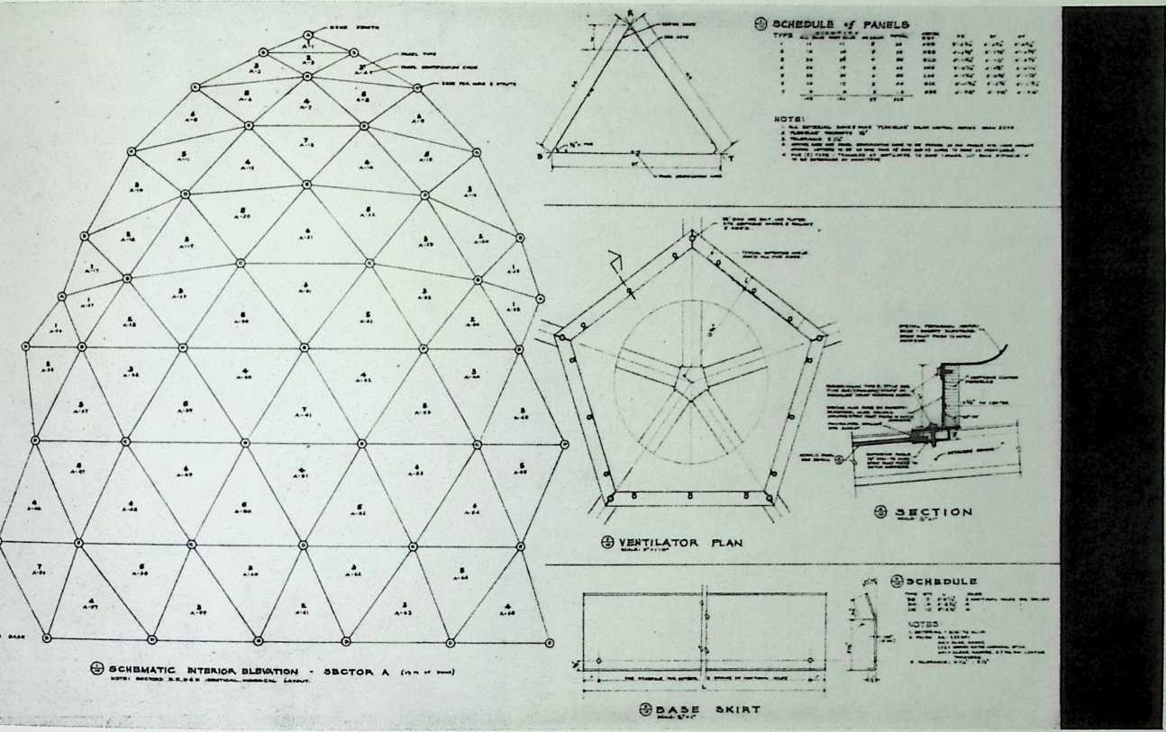
¶ Chapter 2 Yomiuri Golf Club Geodesic Dome, Tokyo 1961–1963
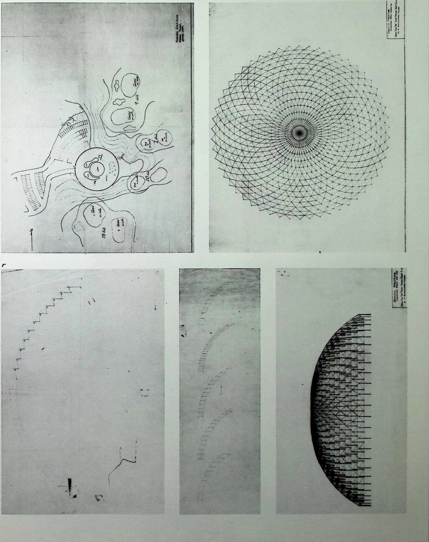
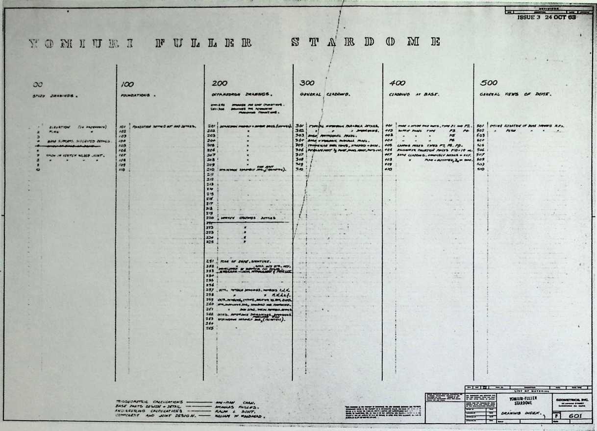
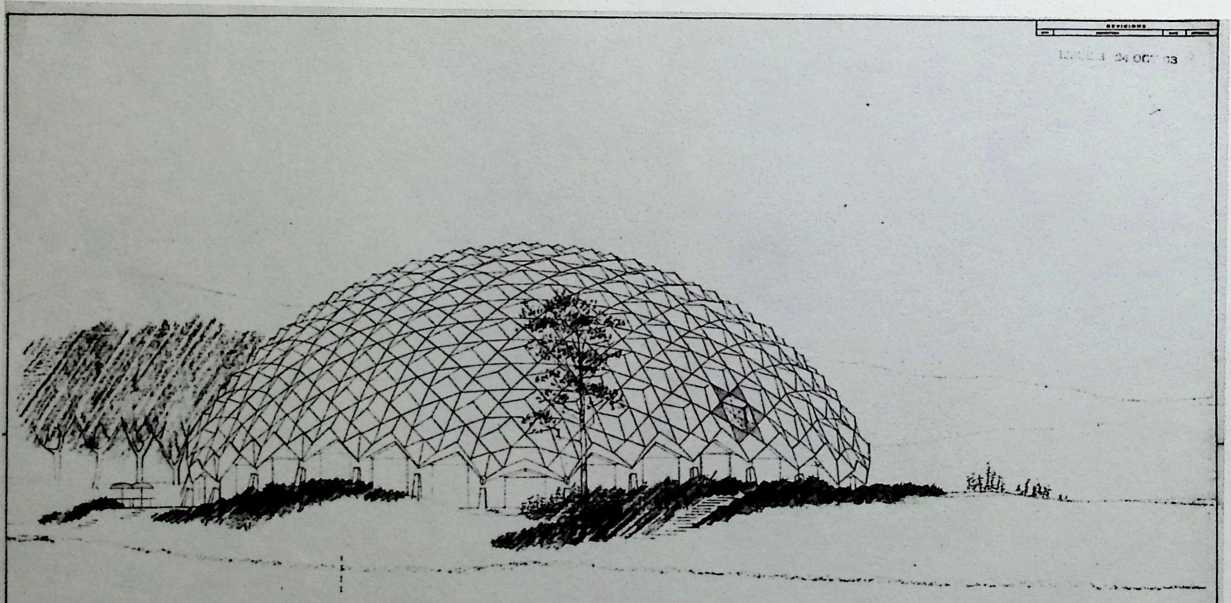
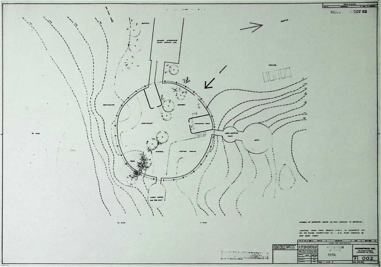
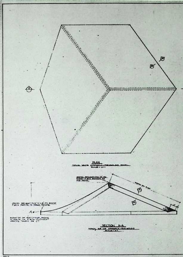
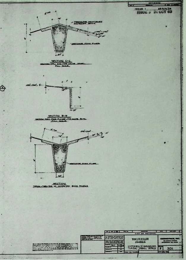
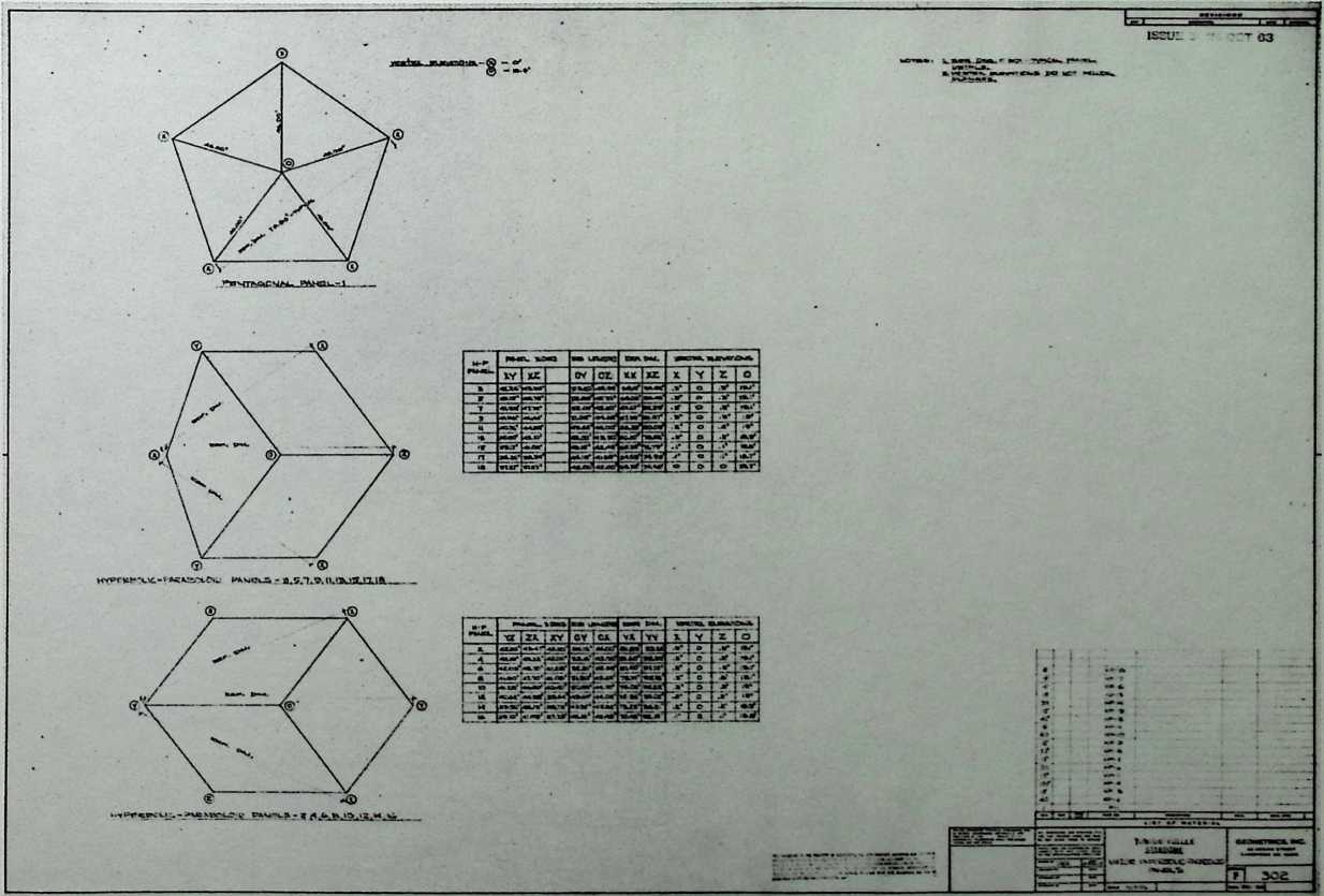
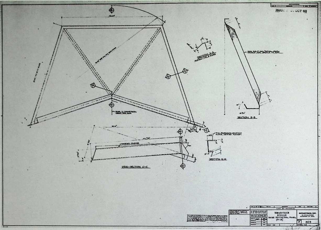
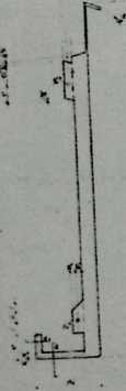
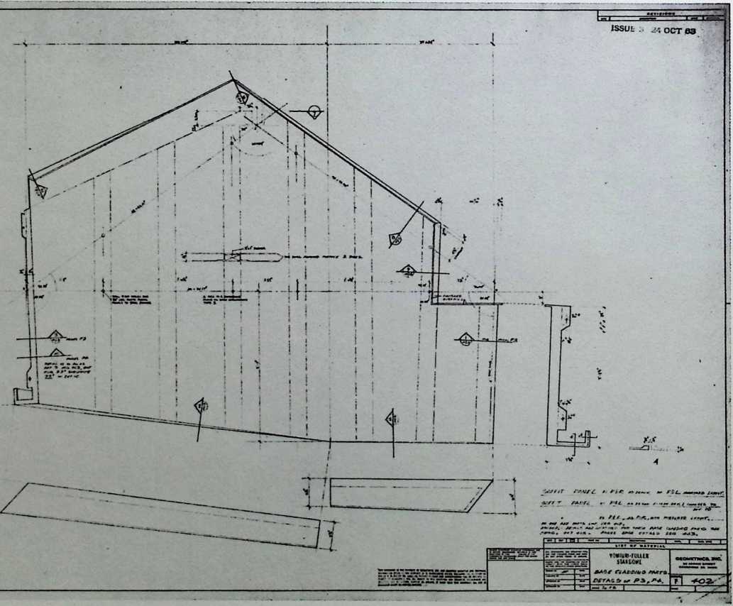
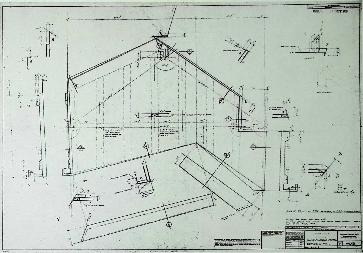
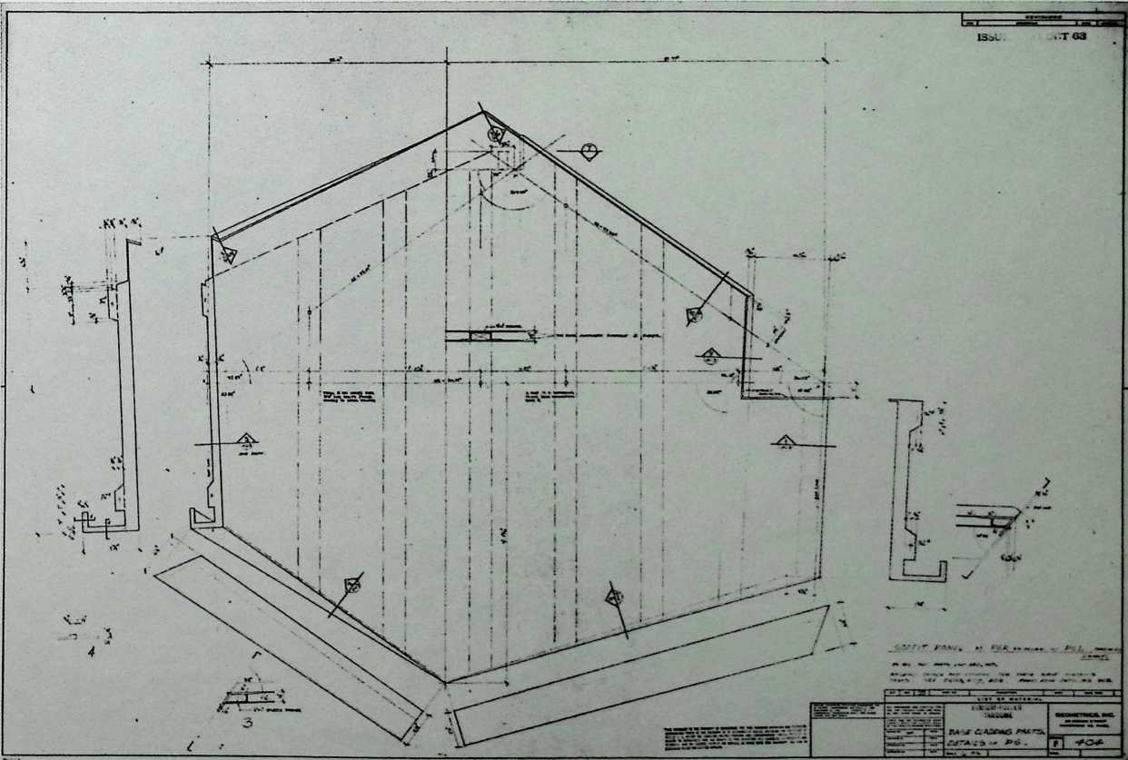
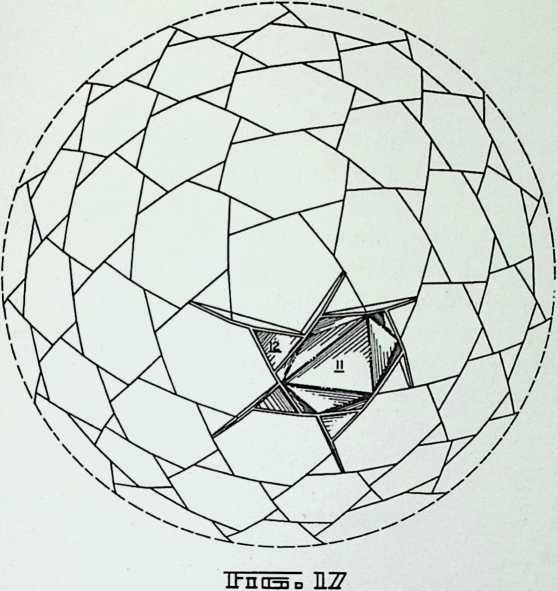
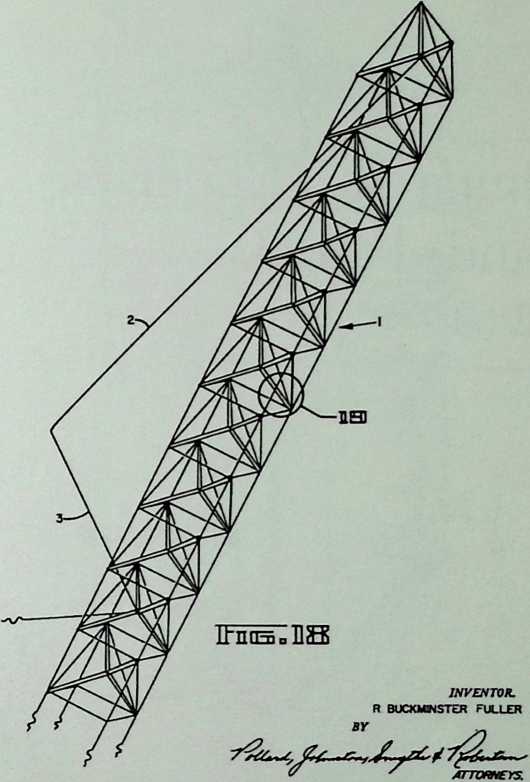
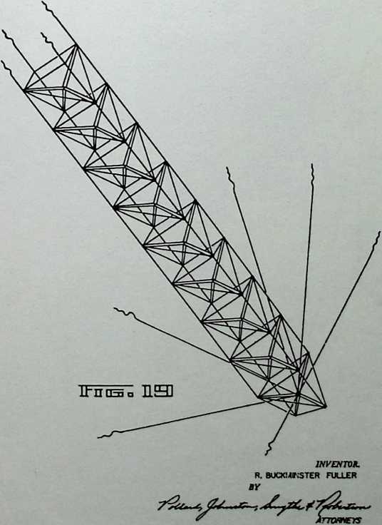
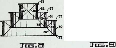
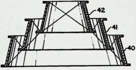
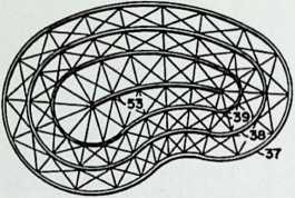
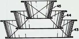
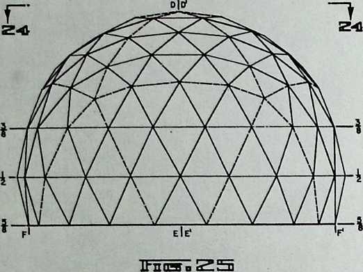
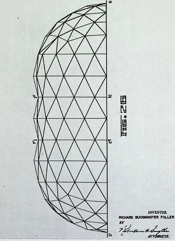
The Yomiuri Golf Club project began in a sketch of 1961 that may be Fuller’s earliest attempt to design an aspension structure. An aspension dome is a set of vertical tube supports arranged concentrically and stacked from the ground to the apex in progressively shorter sizes. They are supported and held in place by metal cables held in tension. This project evolved from a half to a third of a sphere. The intermediate phase of the design called for a radomelike structure with portholes, later called the monohex. But this was abandoned eventually for the aspension system. The base was also set above the ground, like the national headquarters of the American Society for Metals, although the supports in the 170-foot Japanese building were triangular volumes clad in metal panels.
18 if TWNCATHBLE TEHSEGfclTY SPHERE.
INTtfWiTloNAL PATENTS
THE GEODESIC REVOLUTION, P/XRT 2–5
ii i ain
45KIB
10 THE GEODESIC REVOLUTION. PART 2
![]()
![]()
ffiggjg |
s 2 •>41 |
||||
24 THE GEODESIC REVOLUTION, PART 2
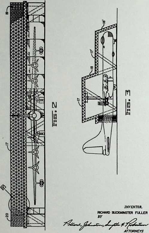
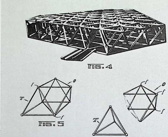
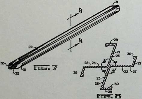
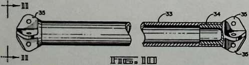
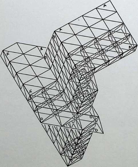
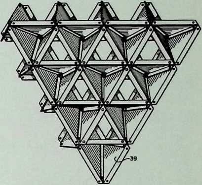
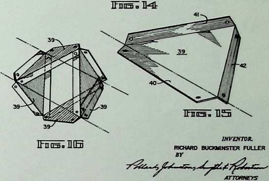
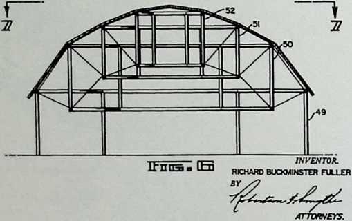
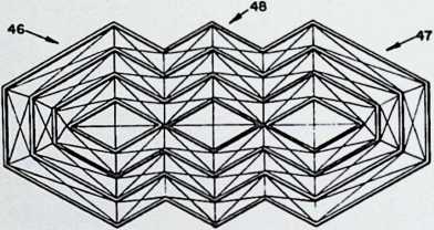
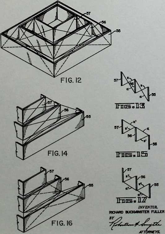
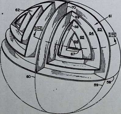
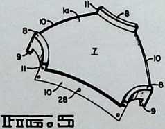
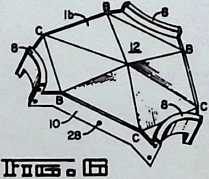
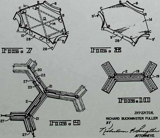
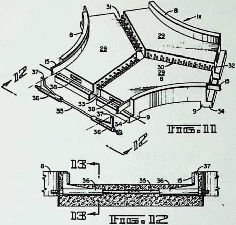
¶ Chapter 3 Octet Truss Patent 5/30/61
The octahedron truss is the most adaptable construction unit because it can fill any kind of space. It combines the octahedron and the tetrahedron and can be flat or curved in any direction.
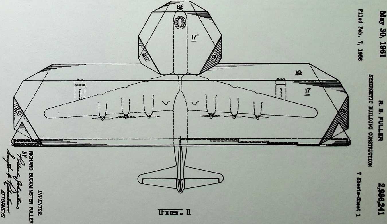
M*y 30, 1961 r. b, fuller 2,986,241
SYNERGETIC BUILDING CONSTRUCTION Filed Fib. 7, 1956 7 Sheeti-Sbeet 2
May 30, 1961
Filed Feb. 7, 1956
R. B. FULLER 2,986,241
SYNERGETIC BUILDING CONSTRUCTION
7 Sheeti-Sbeet 3
Itnoso (H
May 30, 1961
Filed Fib. 7, 1956
R. B. FULLER
SYNERGETIC BUILDINC CONSTRUCTION
2,986,241
May 30, 1961 r. B- fuller 2,986,241
SYNERGETIC BUILDING CONSTRUCTION
Filed Feb. 7, 1956 7 gbeetl-Sbeet B
7 Sbeeti-Sbeet 4
ItnOSo SO
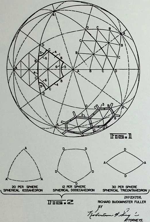
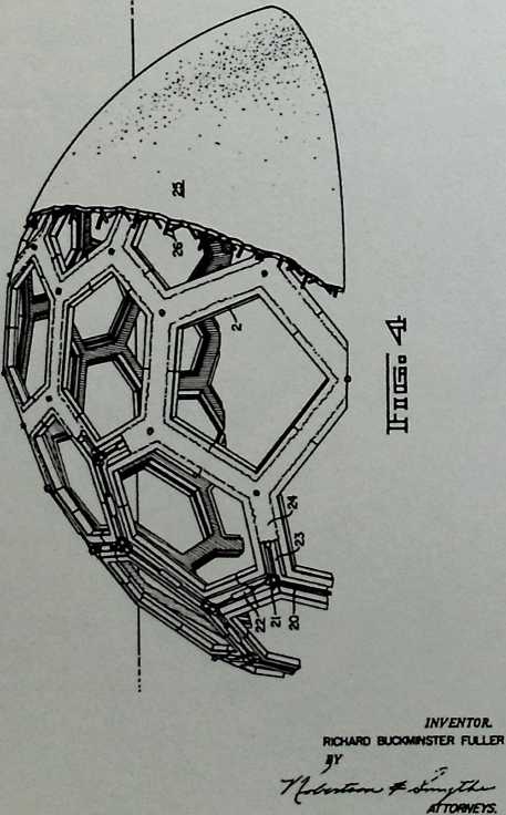
INVENTOR.
RICHARD BUCKMINSTER FULLER
BY
![]()
![]()
II
May 30, 1961
Filed Fob. 7, 1956
R. B. FULLER
SYNERGETIC BUILDINC CONSTRUCTION
2,986,241
7 Sbeete-Sbeet 6
ITniSo 113
May 30, 1961 r. a fuller 2,986,241
SYNERGETIC BUILDING CONSTRUCTION
Filed Feb. 7, 1956 7 Sbeete-Sboet 7
![]()
¶ Chapter 4 Residence of R. Buckminster Fuller and Anne Hewlett Fuller, Carbondale, Illinois 1960
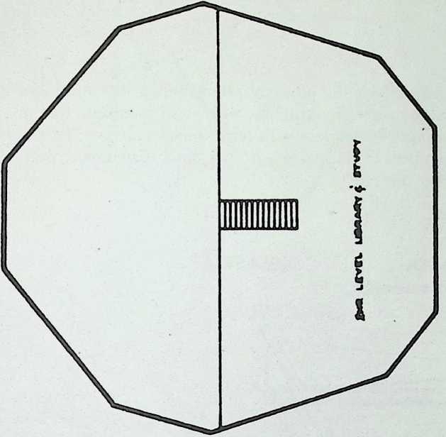
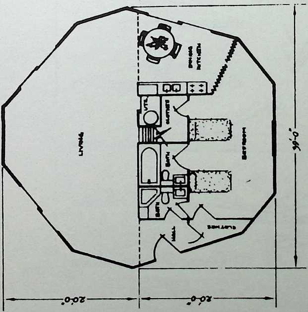
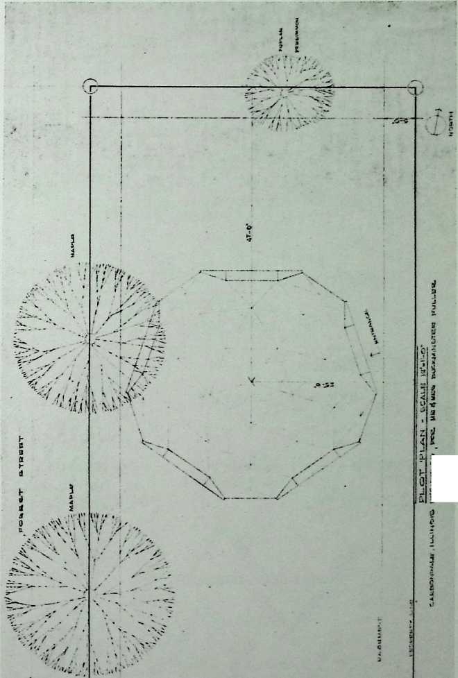
Fuller’s own home may be the only geodesic residence that he lived in during his lifetime. Located in Carbondale, Illinois, the two-story dome has a study on a loft platform and a relatively large living room. Notwithstanding his enthusiastic experimentation with the skybreaks, Fuller’s own house is fenestrated conservatively. It was designed with Al Miller of the Pease Company of Ohio.

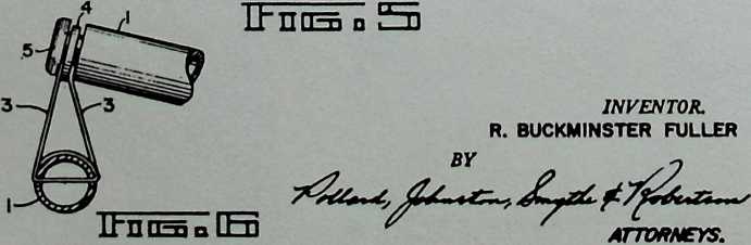
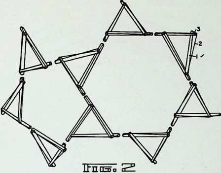
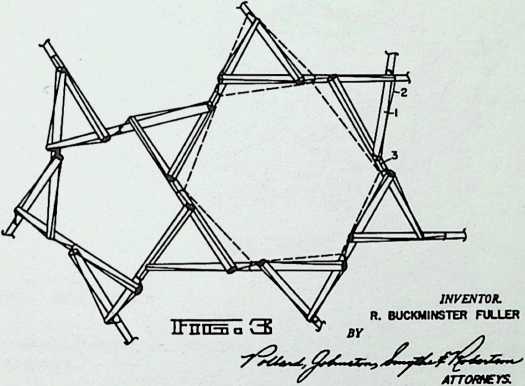
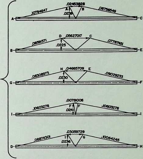
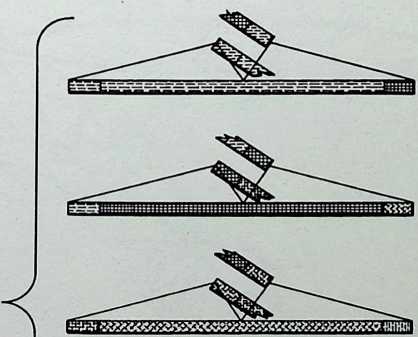
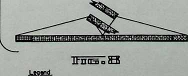
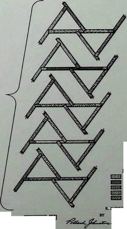
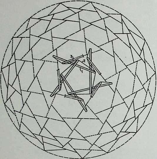
¶ Chapter 5 Tensegrity Patent 11/13/62
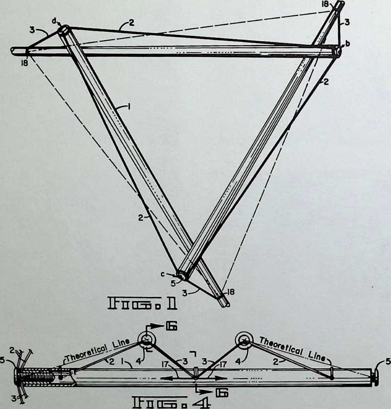
Tensegrity is the physical phenomenon that produces a stable geometric structure with solid members that are arranged in tandem with tense metal cables. The solid members of this system do not touch or support each other directly.
Nov. 13, 1962 r. b. fuller 3,063,521
TENSILE-INTEGRITY STRUCTURES Filed Aug. 31, 1959 13 Sheets-Sheet 1
![]()
Nov. 13, 1962
Filed Aug. 31. 1959
R. B. FULLER 3,063,521
TENSILE-INTEGRITY STRUCTURES
13 Sheet»-Sbeet 2
Not. 13,1962
Filed Aug. 31. 1959
R. a FULLER 3,063,521
TENSILE-INTEGRITY STRUCTURES
13 Sbeet»-Sbeet 3
UQffl±
- SILVER
- BLACK
- ORANGE
- PURPLE
- YELLOW
INVENTOR.
R. BUCKMINSTER FULLER
Nov. 13, 1962
Filed Aug. 31. 1959
R. B. FULLER
TENSILE-INTEGRITY STRUCTURES
3,063,521
Nov. 13, 1962
R. B. FULLER
TENSILE-INTEGRITY STRUCTURES
13 Sheete-Sbeet 4
SILVER INVENTOR.
RBHa BLACK *■ BUCKMINSTER FULLER
£5553 ORANGE BY
tUtimi purple (7s s-
EHS] YELLOW '
3,063,521
13 Sbeet»-Sbeet 5
Filed Aug. 31. 1959
ITnoso SO
OMummum
BLACK
ORANGE
PURPLE
YELLOW
LSQlDl
SILVER
INVENTOR.
R. BUCKMINSTER FULLER
ATTORNEYS.
![]()
![]()
![]()
Nov. 13, 1962
Filed Av*. 31. 1939
R. B. FULLER 3,063,521
TENSILE-INTEGRITY STRUCTURES
13 Sb«et»-5b.«t 6
Nov. 13, 1962
Filed Aus. 31. 1959
R. a FULLER
TENSILE-INTEGRITY STRUCTURES
3,063,521
13 Sheeta-Sheet 7
ItHOSoIlOLl)
irntBo DU
INVENTOR.
R. BUCKMINSTER FULLER
INVENTOR.
R. BUCKMINSTER FULLER
Nov. 13, 1962 r. a fuller 3,063,521
TENSILE-INTEGRITY STRUCTURES
Filed Aug. 31. 1939 13 Sh…t»-5b«et 8
Nov. 13, 1962
Filed Auk. 31. 1959
r. a. fuller 3,063,521
TENSILE-INTEGRITY STRUCTURES
13 Sheete-Sheet 9
attoweys.
'ATTORNEYS.
![]()
![]()
Nov. 13, 1962 r. b. fuller 3,063,521
TENSILE-INTEGRITY STRUCTURES
Fl ltd Aug. 31. 1959 13 Sh»ts-Sh«it 10
Nov. 13, 1962 r. a fuller 3,063,521
TENSILE-INTEGRITY STRUCTURES
Flltd Aug. 31. 1959 13 SlmlB-ShMt 11
INVENTOR.
R. BUCKMINSTER FULLER
![]()
Nov. 13, 1962 r. b. fuller 3,063,521
TENSILE-INTEGRITY STRUCTURES
Fl ltd Aug. 31. 1959 13 12
Nov. 13, 1962 r. a fuller 3,063,521
TENSILE-INTEGRITY STRUCTURES
Filed Aug. 31, 1959 13 She«t»-Sh«et 13
ITnasiSIl
INVENTOR
R. BUCKMINSTER FULLER
BY
![]()
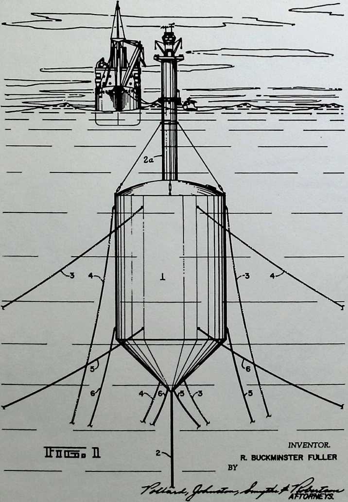
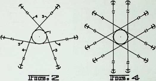
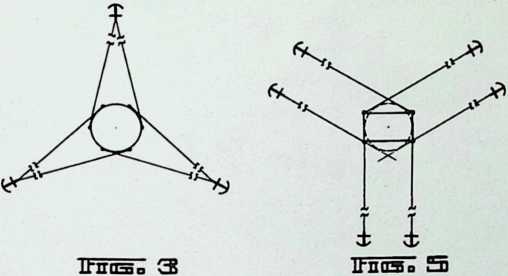
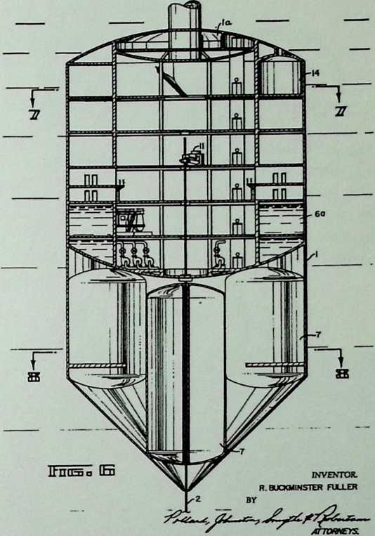
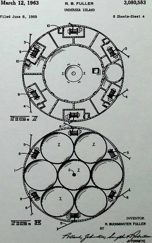
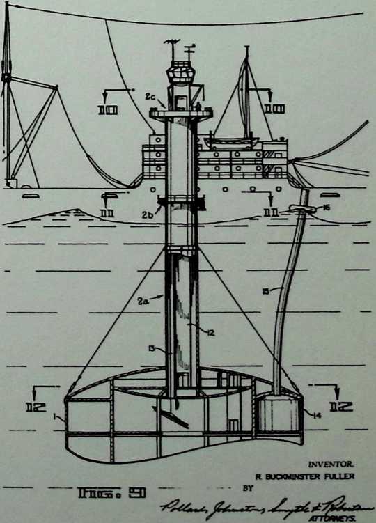
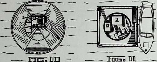
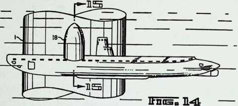
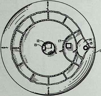
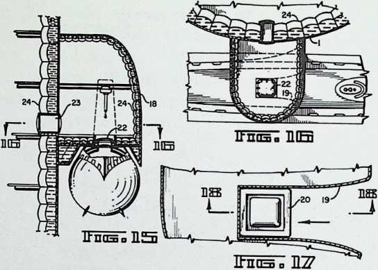
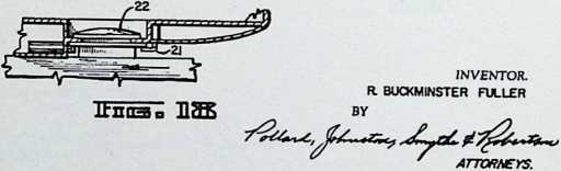
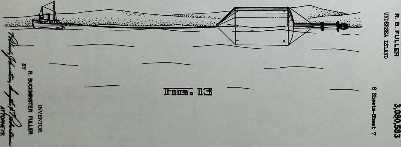
¶ Chapter 6 Submarisle (Undersea Island) Patent 3/12/63
The submarisle represents Fuller’s return to the idea of floating islands that he had explored during the twenties. The technological advances realized by the sixties would have made submarisle feasible. It is essentially a submerged depot for the loading and unloading of goods from submarines, eliminating the need for a harbor and ensuring the safe delivery of goods during bad weather. The semisubmerged vessel is anchored below surface turbulance.
March 12, 1963
3,080,583
Filed June 8, 1959
R. B. FULLER undersea island
8 Sheets-Sheet 1
March 12, 1963
Filed June 8, 19S9
R B. FULLER
UNDERSEA ISLAND
3,080,583
8 Sheete-dheet 2
March 12, 1963
Filed June 8, 1959
R. B. FULLER
UNDERSEA ISLAND
3,080383
8 Sheets-Sheet 3
March 12, 1963
Filed June 8. 1959
R- Be FULLER
UNDERSEA ISLAND
3,080383
8 Sheets-Sheet S
![]()
March 12, 1963
Filed June 8, 1959
3,080,583
8 Sheata-ShBat 6
March 12, 1963
Filed June 8, 1959
R. B. FULLER
UNDERSEA ISLAND
3,080,583
8 Sheoto-Sheot 8
INVENTOR.
R. BUCKMINSTER FULLER
BY
![]()
![]()
![]()
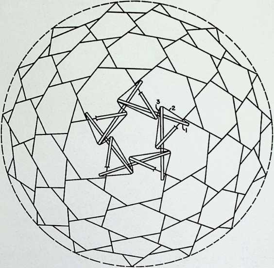
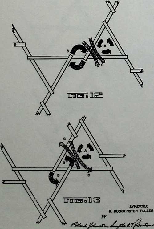
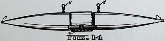
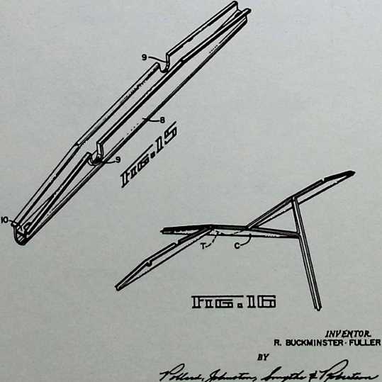
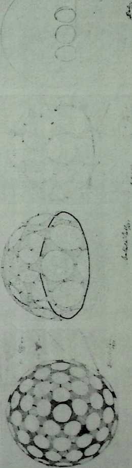
¶ Chapter 7 Tensegrity Chandelier for Princess Margaret 1964
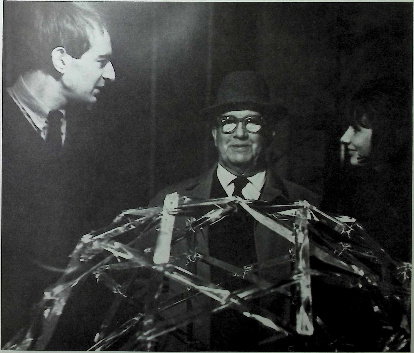
One of Fuller’s most conspicuous public gestures during the sixties was the presentation of this geodesic sphere of crystal struts and silver wires to Princess Margaret, thus realizing in sumptuous materials and bringing to royal attention the innovational and universal principles he had developed during the early fifties. This glittering monument to the concepts of tensegrity and the thirty-one great circles was built by James and Gill Meller.
The thirty-two year association of the architect Shoji Sadao with the inventor R. Buckminster Fuller helped establish the latter as a serious shaper of the human environment. The designs produced by the architectural firm of Fuller & Sadao from 1964 until 1983 are distinguished both by the originality of Fuller’s imagination and the practicality of Sadao’s architectural details. When Sadao joined Fuller, both men resolved to concentrate on the potential of architecture to influence the evolution of modern society. The most famous product of this inventor—architect liaison is the towering geodesic dome built for Expo ‘67, the world’s fair held in Montreal. In this building, structural invention is the most obvious aspect of Fuller’s design, but Sadao and scores of engineers were responsible for the details of its realization.
¶ Chapter 8 Fuller & Sadao 1964–1983
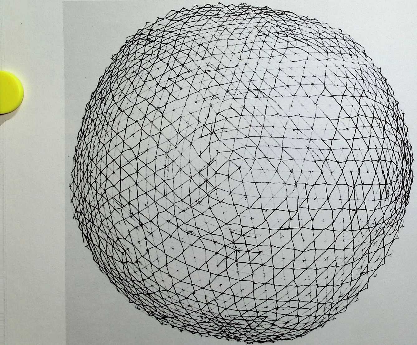
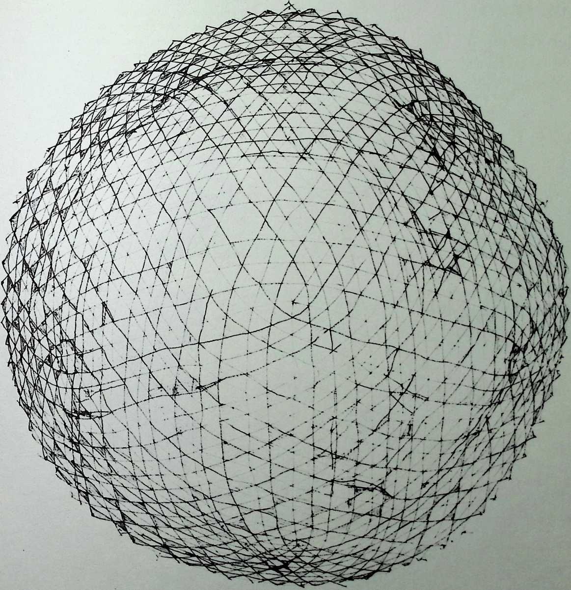
Shoji Sadao, was born and raised in Los Angeles. He earned his bachelor’s degree in architecture at Cornell University in 1954. It was there in Ithaca in 1952 that he first met Fuller, who had been engaged as a guest lecturer. Sadao became his most avid pupil and assisted him with the erection of a twenty-foot lath globe comprising the thirty-one great circles that formed the basis of Fuller’s geodesic theories. This venture united the two in creative endeavor for over three decades.
Soon after the successful erection of the geodesic globe at Cornell, Fuller employed Sadao again to help realize a new edition of the Dymaxion Airocean World Map (1954). Notwithstanding the cartographic nature of these debut commissions, Sadao’s contribution to Fuller’s design team during the fifties was chiefly architectural. Fuller’s projects of this period were basically of two types, the most important of which involved the materialization of abstract structural notions. The more practical, if less interesting, projects were the lightweight, demountable geodesic structures Sadao helped design for the U.S. Marine Corps and the Army Quartermaster Corps. Interesting examples of the abstract designs are the two thirty-six-foot, perforated paperboard domes Sadao designed for the Biennale in Milan in 1954, which functioned mainly to demonstrate geodesic principles. But the most significant effort of these years was the tensegrity mast, designed by Sadao with Edison Price for the Fuller exhibition at the Museum of Modern Art in New York in 1959.
Sadao was affiliated with Edison Price, Inc., a lighting manufacturer of some distinction, from 1959 until he joined Fuller in 1964. He was job captain for several of their most important commissions including:
the Four Seasons Restaurant and the Seagram Building lobby in New York City, the Munson-Williams-Proctor Institute in upstate New York, and the Amon Carter Museum in Fort Worth, Texas.
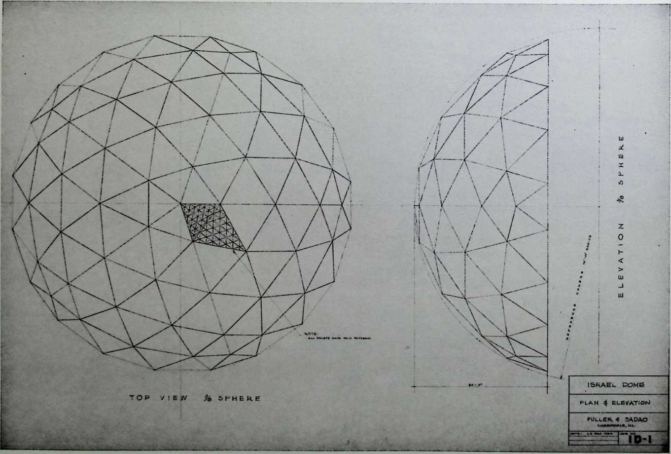
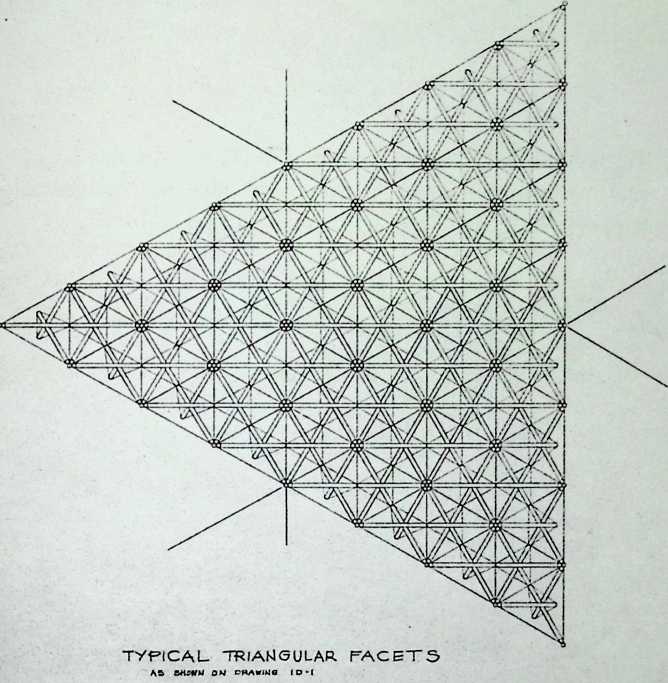
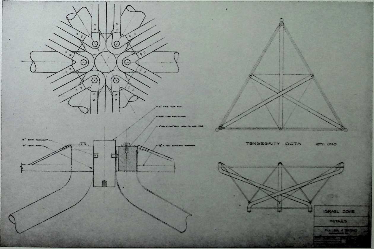
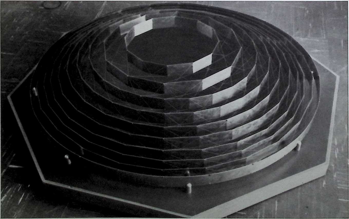
¶ Chapter 9 Tensegrity Dome for Israel Fuller & Sadao, 1964
This tensegrity dome designed for an unspecified function in Israel is three-eighths of a sphere and 150 feet in diameter. Each unit of this aluminum tube and steel cable structure would have been covered by a transparent acrylic pane. Although completely dependent on the structural principles of tensegrity, it would have been one of the most complex of Fuller’s creations, with its interplay of bent tubes and winding metal cables.
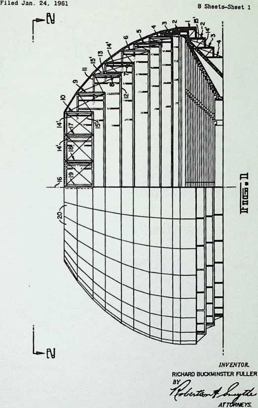
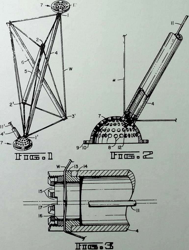
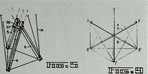
¶ Chapter 10 Aspension Geodesic Structures Patent 7/7/64
The principle of the suspension bridge is utilized in this invention, creating a domical space of vertical tube supports held in shape with tense metal cables.
July 7, 1964
R. B. FULLER
SUSPENSION BUILDING
3,139,957
July 7, 1964
Filed Jan. 24, 1961
R. B. FULLER
SUSPENSION BUILDING
3,139,957
8 Sheets-Sheet 2
irnas
INVENTOR.
RICHARD BUCKMINSTER FULLER
July 7, 1964
Filed Jan. 24. 1961
R. B. FULLER
SUSPENSION BUILDING
3,139,957
8 Sheets-Sheot 3
July 7, 1964
Filed Jan. 24. 1961
R. B. FULLER
SUSPENSION BUILDING
3,139,957
8 Sheets-Sheet 4
![]()

![]()
![]()
July 7, 1964 r. B. fuller 3,139,957
SUSPENSION BUILDING Filed Jen. 24. 1961 B Sheets-Sheet 5
July 7, 1964
Filed Jan. 24. 1961
R. B. FULLER
SUSPENSION BUILDING
3,139,957
8 Shoets-Sheot 6
ITnts. H
lt*TTll"ri~a rrii
Lt-nnsnllll
INVENTOR.
RICHARD BUCKMINSTER FULLER
July 7, 1964
Filed Jan. 24. 1961
R. B. FULLER
SUSPENSION BUILDING
3,139,957
8 Sheeta-Sbeet 7
July 7, 1964 R. B. fuller 3,139,957
SUSPENSION BUILDING
Filed Jan. 24. 1961 B sheets-She.t 8
IbnasoIlH
itnasaOSJ
INVENTOR.
RICHARD BUCKMINSTER FULLER
![]()
![]()
![]()
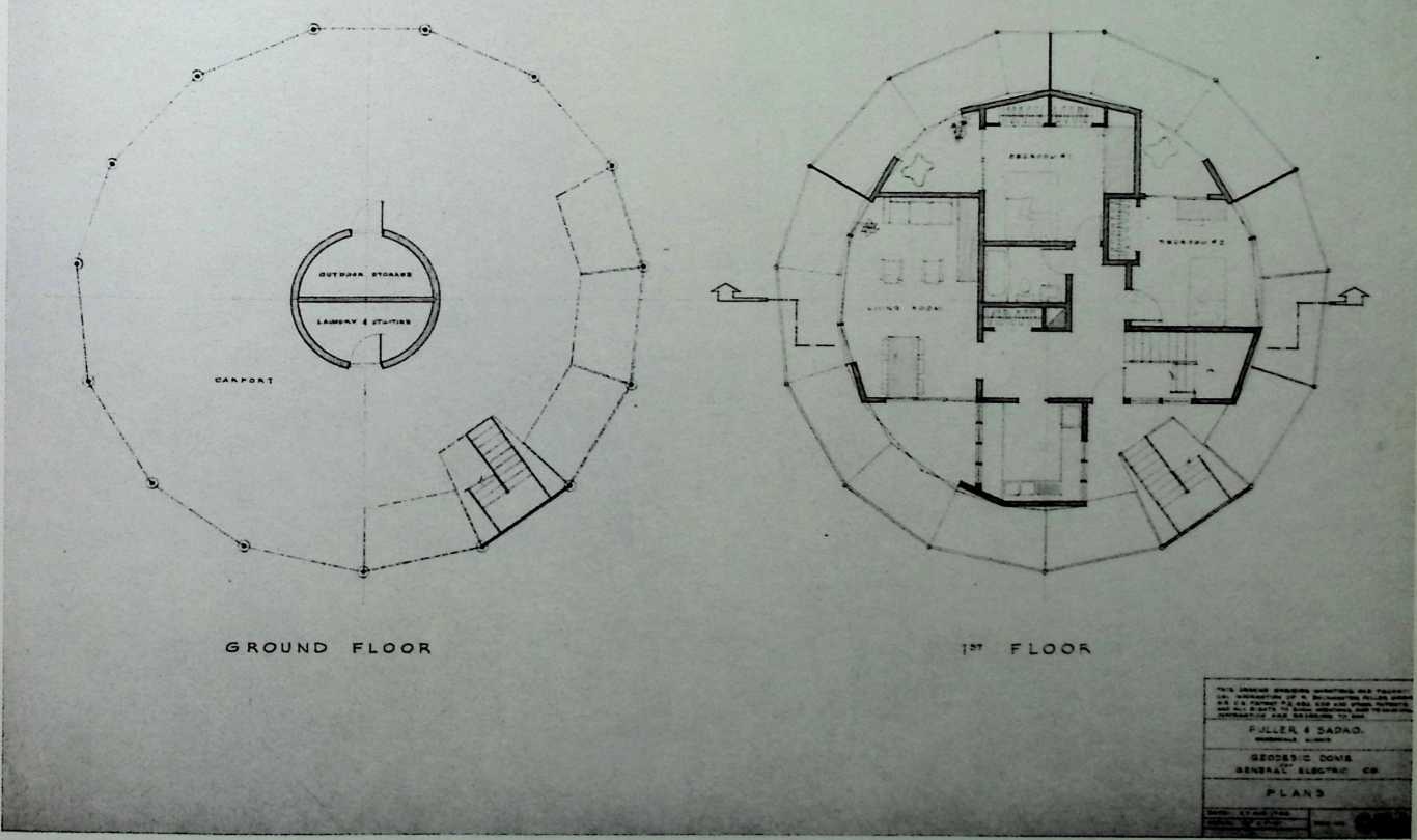
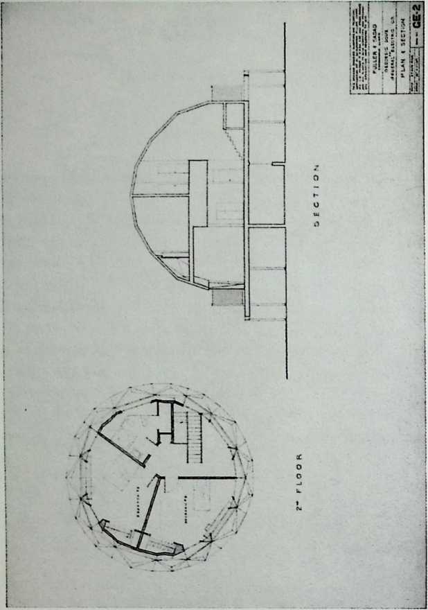
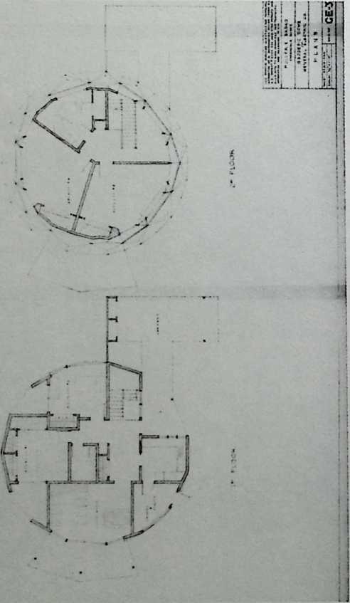
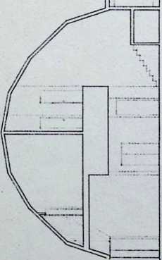
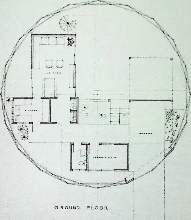
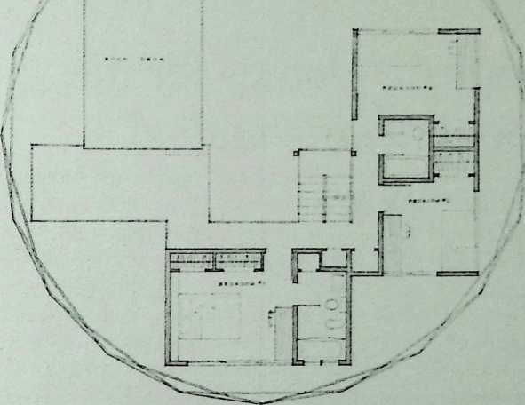
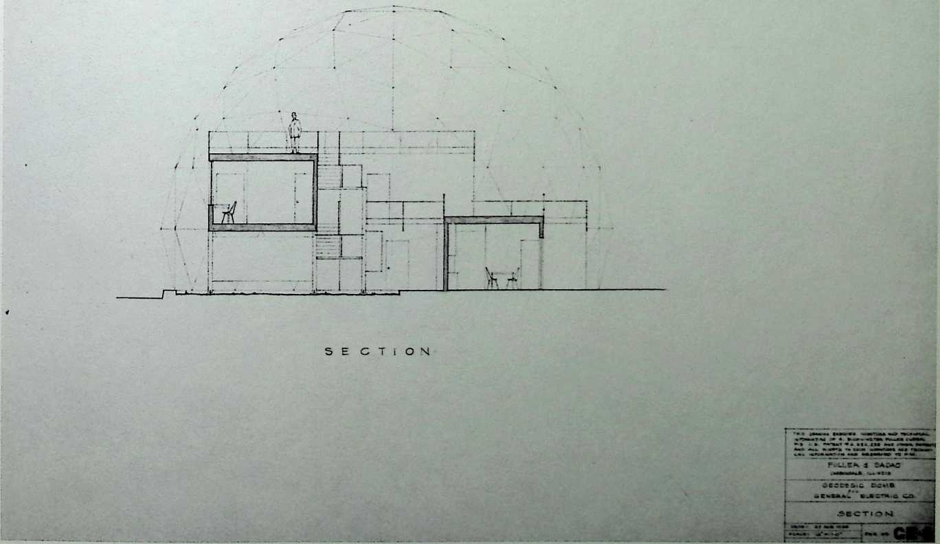
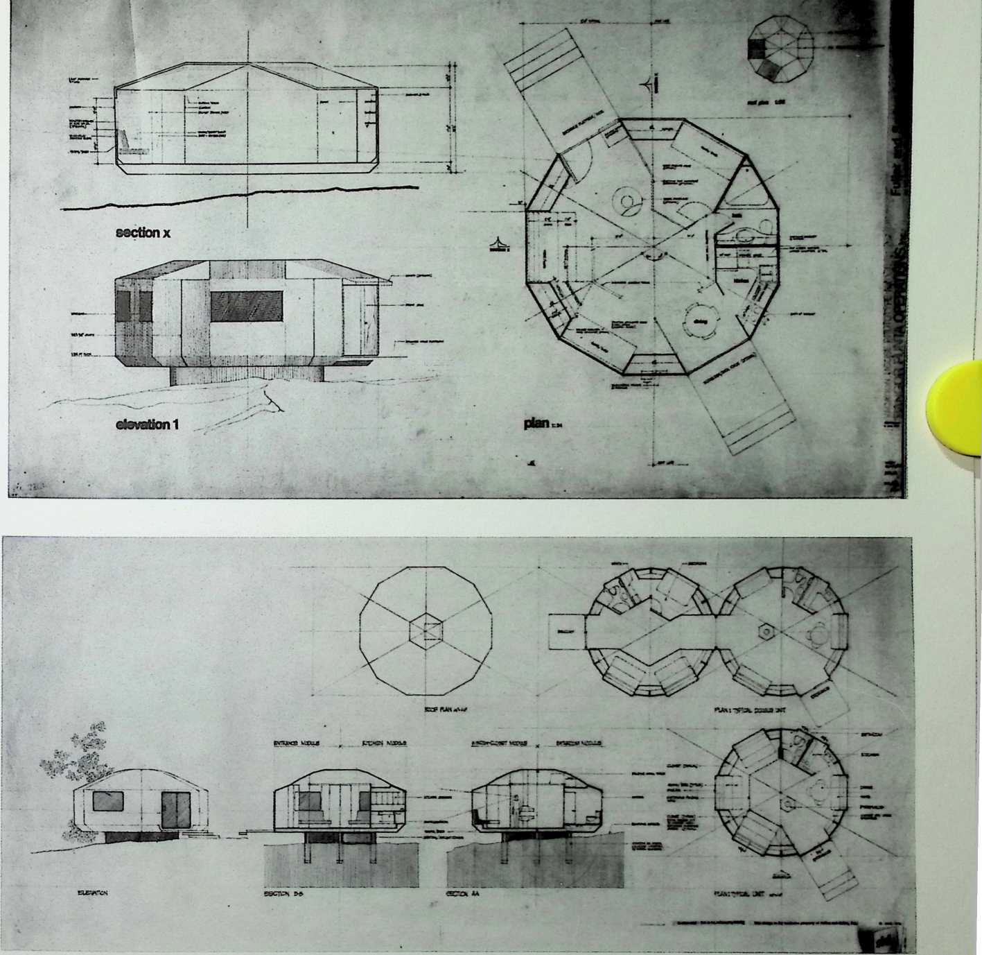
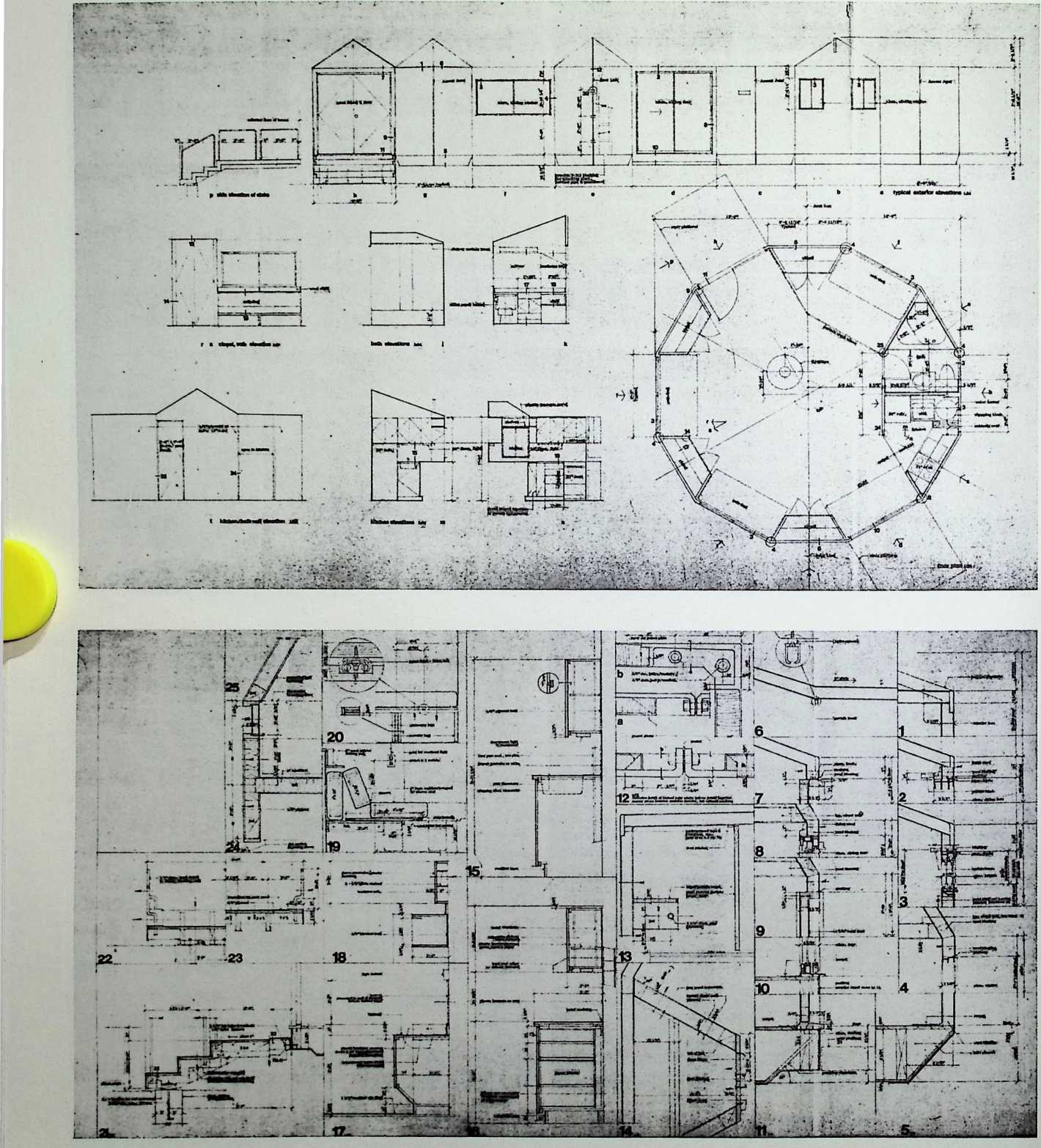
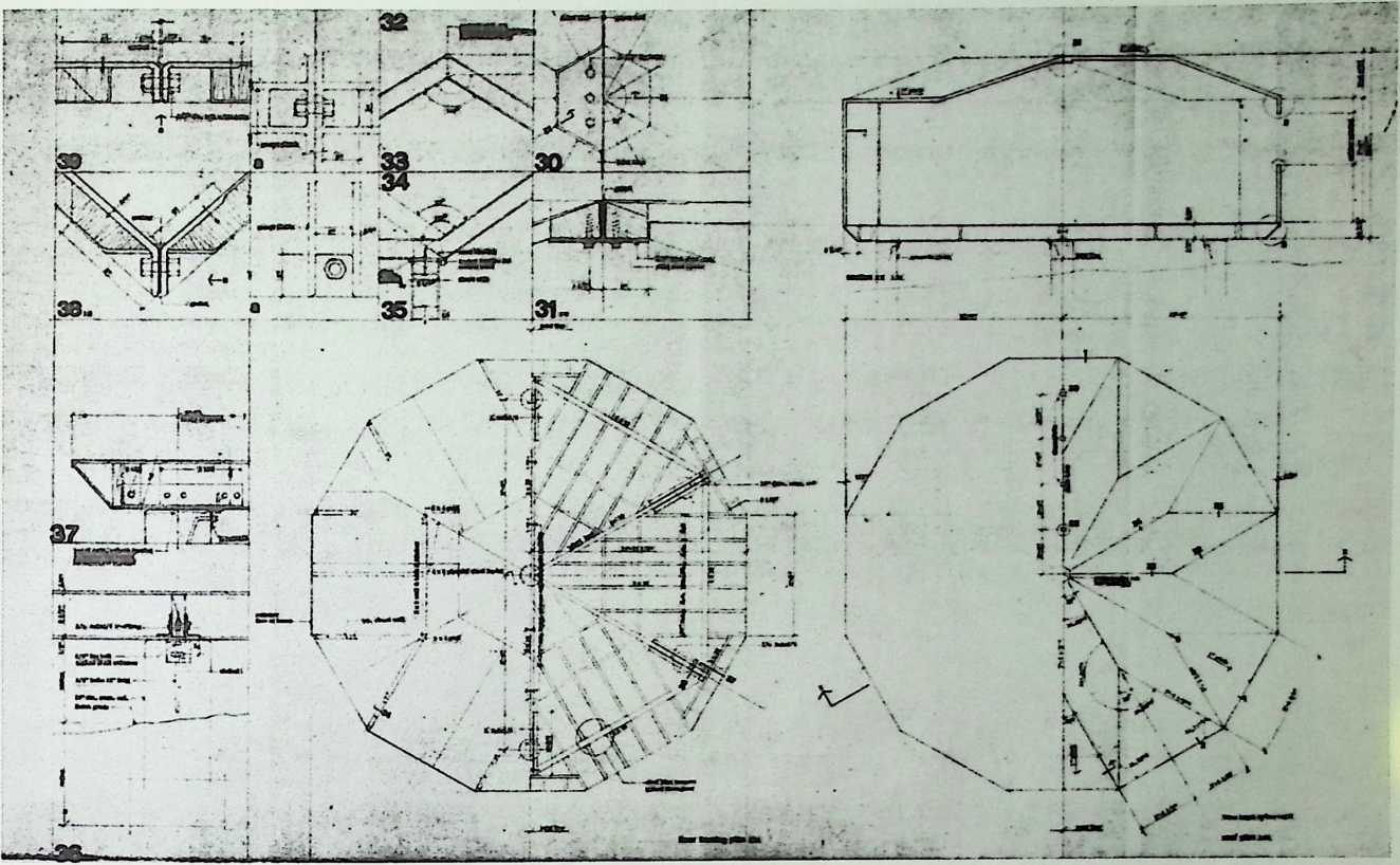
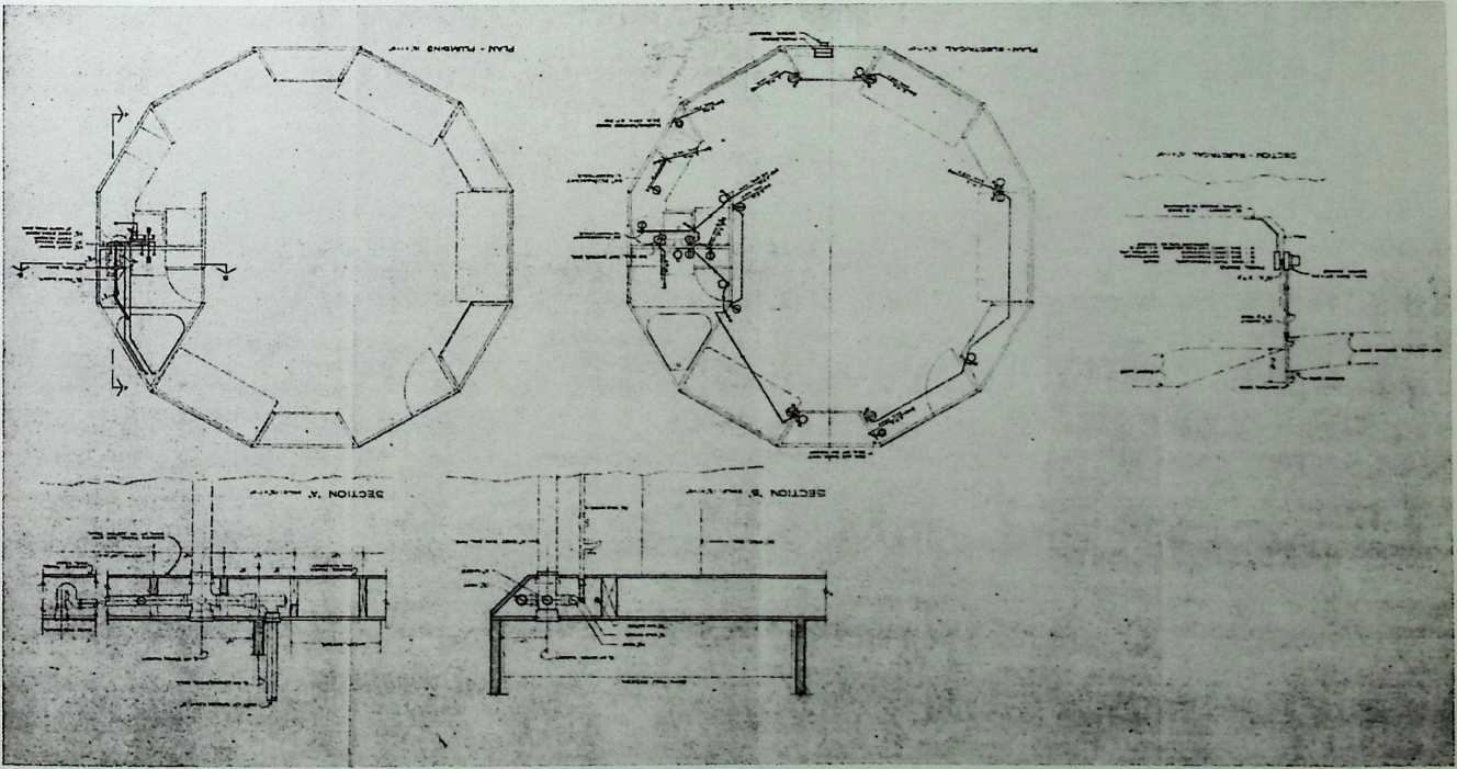
¶ Chapter 11 Geodesic Dwellings for General Electric Fuller & Sadao, 1964
The General Electric (G.E.) Company, which sponsored the radomes of the 1950s, had Fuller design these geodesic dwellings for mass production in 1964. There are two types: the first has a base housing a carport and laundry, four bedrooms, two baths, a living room, and a kitchen—all of which were arranged to fit the curvature of the dome; the second type corresponds with the skybreaks of the late 1940s, in that the rooms are stacked, rectangular volumes and are discrete from the sheltering dome. One sees at a glance that the new domes for G.E. are feasible in terms of contemporary construction, unlike the earlier skybreaks that were decades ahead of their time.
![]()
GE-4
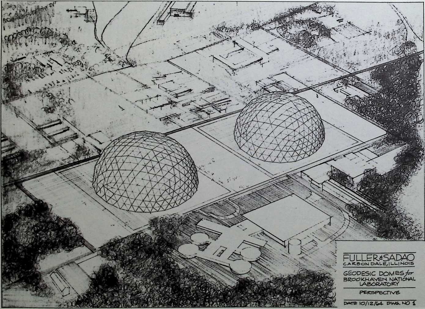
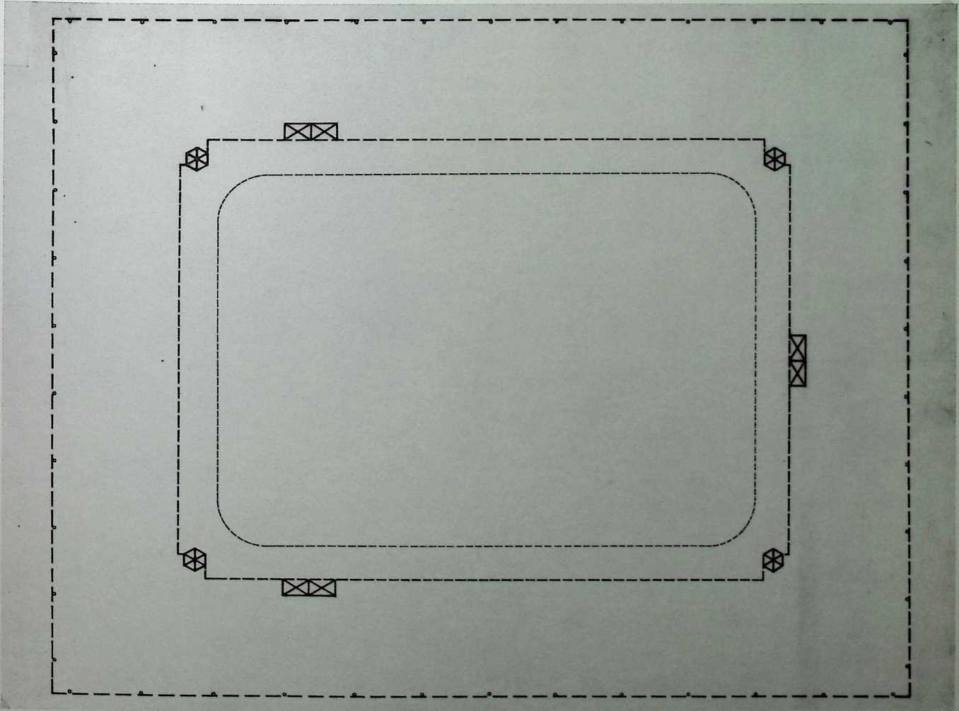
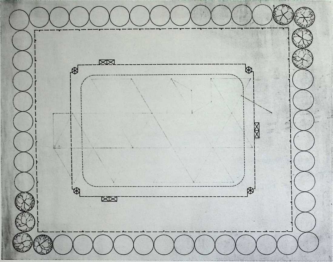
¶ Chapter 12 Geodesic Domes for the Brookhaven National Laboratory Fuller & Sadao, 1964
This single sketch depicts two geodesic domes, each over 100 feet high, designed by Fuller for the Brookhaven National Laboratory in 1964. This Long Island (New York) facility houses a particle accelerator, a nuclear reactor, and medical and biological research centers. Fuller, who was operating out of his office in Carbondale, Illinois, at the time, was not invited to complete the project. Neither Sadao, Fuller’s partner, nor the administration at Brookhaven recall how the domes were intended to function; although a cafeteria building was erected on the site shortly after the designing of the geodesic domes.
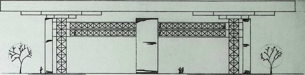
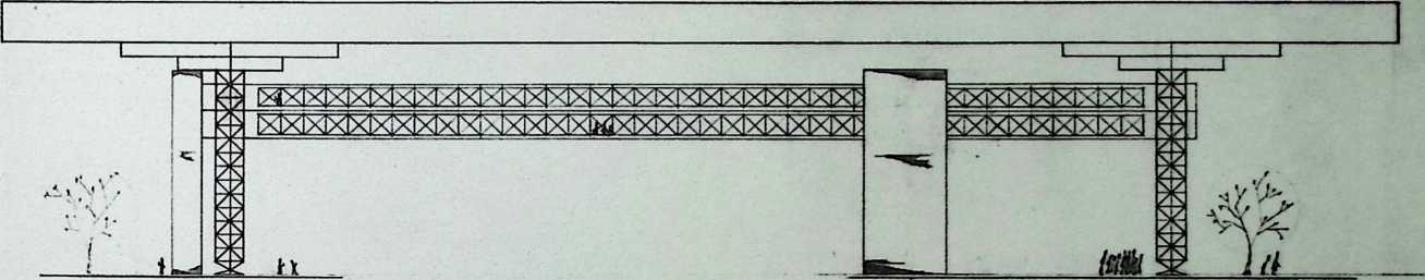
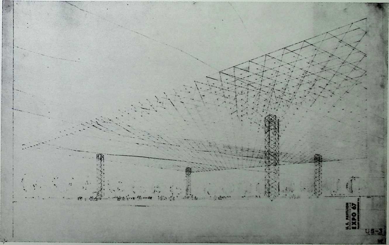
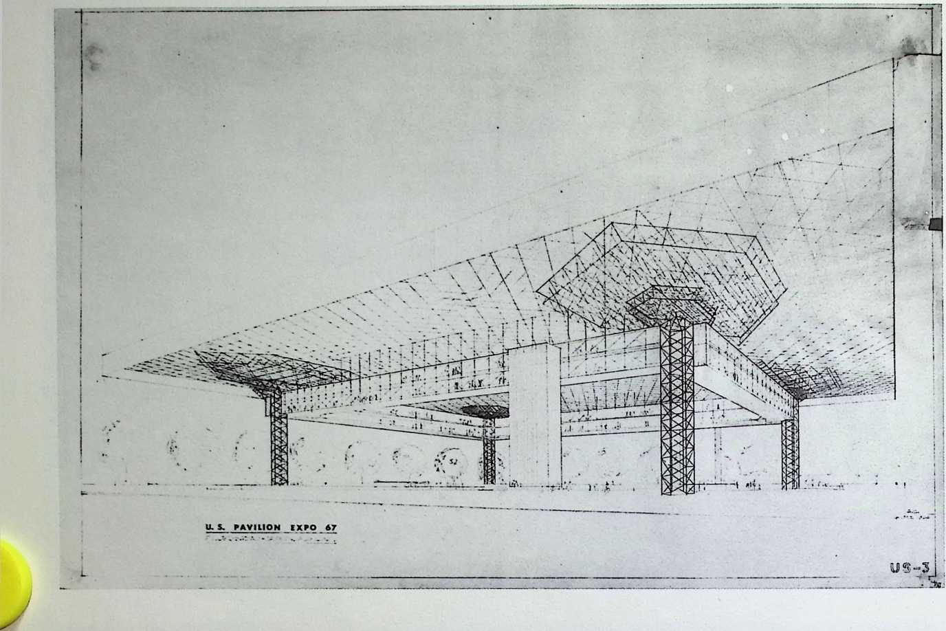
¶ Chapter 13 United States Pavilion Designed for Expo ’67 (Trabeated Truss) Fuller & Sadao, 1964
This important design commission came to Fuller from Jack Masey, a former student of his at Yale, and the director of the exhibition. There was no competition for the United States Pavilion. This initial project is a vast truss on four pylons, perhaps inspired by Fuller’s study of the octet truss. The exhibition space was suspended from the uppermost truss and was to be reached by a single tower of elevators. In the end the plan was rejected because the Dymaxion World Map, Fuller’s intended exhibit, was preempted by a broader group of themes, among which were Hollywood and the lunar landing (then three years in the future). AH of the designers involved were agreed that these themes would be accommodated better in a geodesic dome.
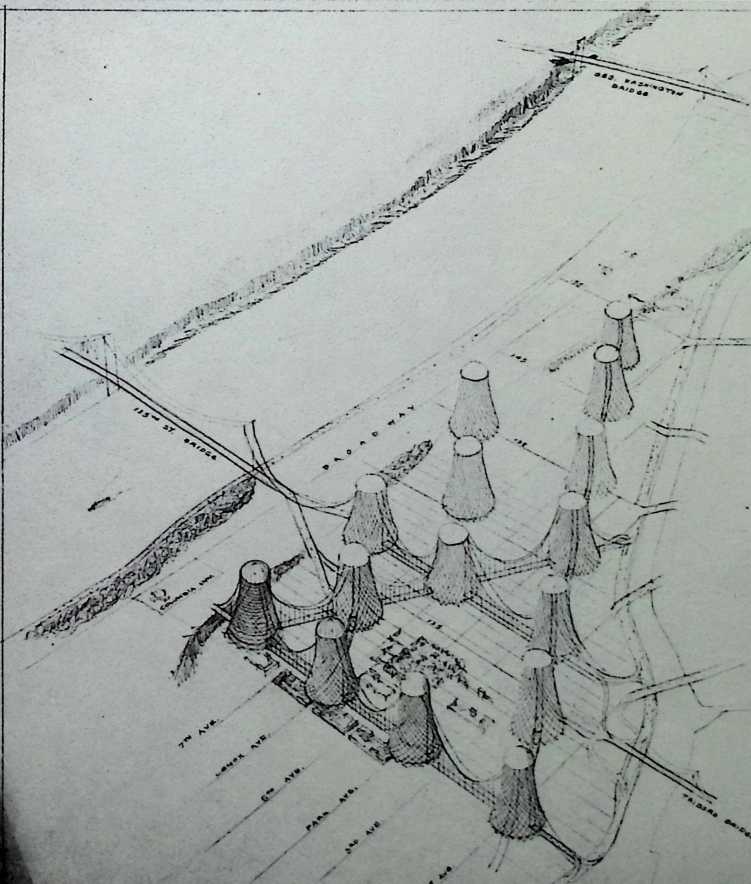
¶ Chapter 14 Harlem Redesign, New York City Fuller & Sadao, 1964
This dramatic redesign of Harlem during the 1960s could not have come too soon, although it actually did not call for the complete demolition of the neighborhood. These fifteen towers, if constructed, would have looked like the cooling towers of typical nuclear power plants. But, unlike the parabolic towers on which they were based, Fuller’s dwellings would have been one hundred stories each and housed an average of seventy- five families per floor. Each would have connected to the other via a suspension bridge, like a reprise of Fuller’s Utopian schemes of the late twenties. The new towers would have been spread out over an area bordered by 110th Street to the south and by 150th Street to the north.
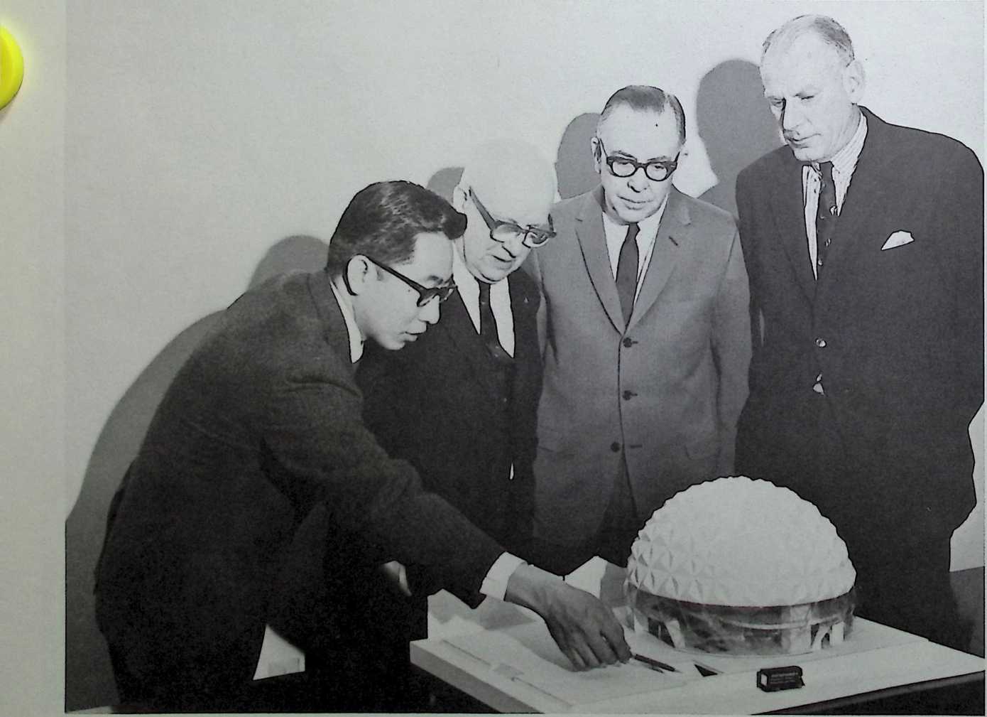
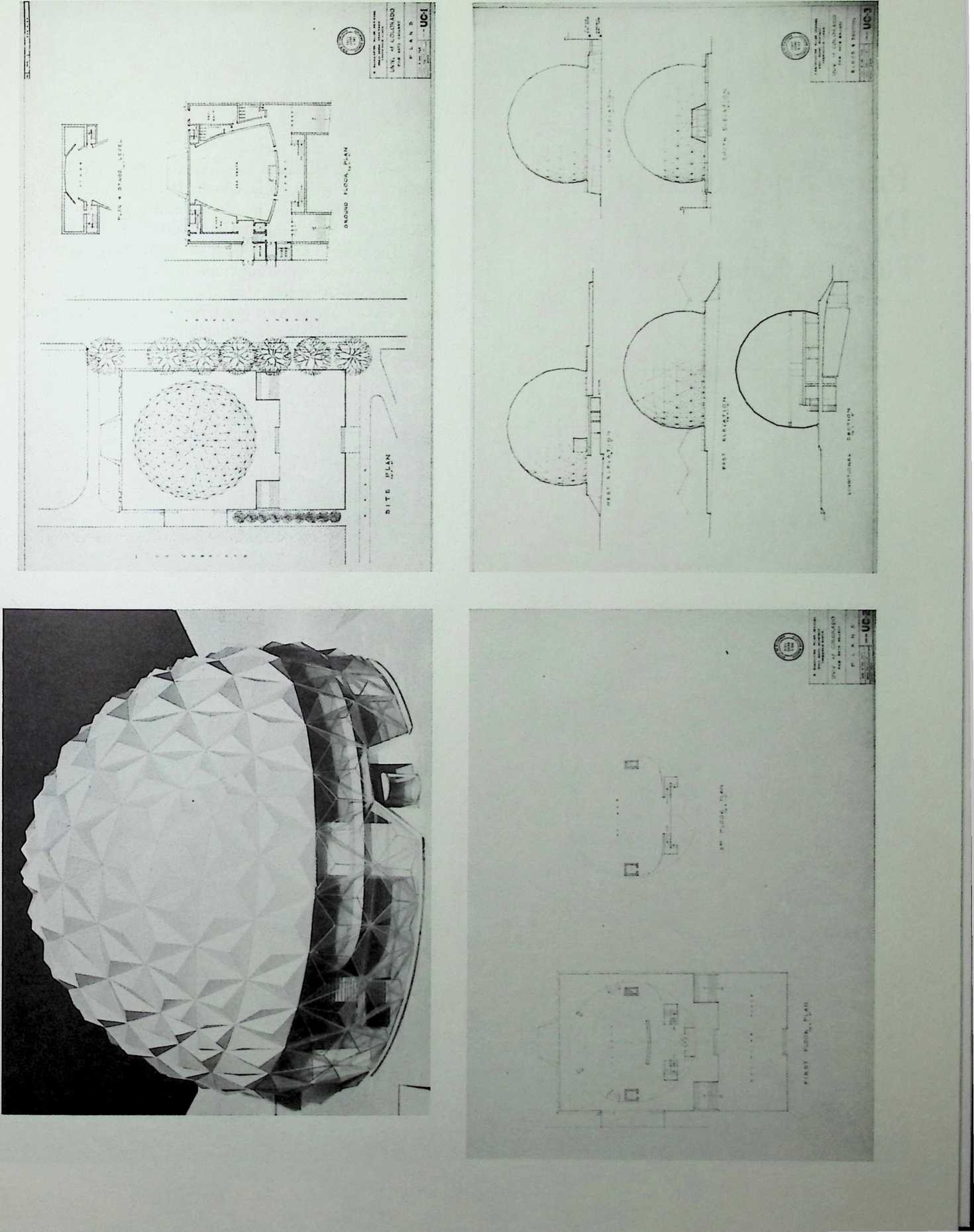
¶ Chapter 15 Fine Arts Gallery of the University of Colorado Fuller & Sadao, 1965
The Fine Arts Gallery of the University of Colorado combines a 650-seat auditorium, a two-story gallery, and a geodesic dome. One would have entered via a ceremonial masonry plinth and four graceful staircases to three rhombic main entrances. Through revolving doors, one encounters the stairway to the second level of the gallery. The stage entrances along the back side of the complex also accommodate the loading and unloading of works of art. Architecturally, the gallery would have been one of this design team’s finest works, with the interesting juxtaposition of the opaque roof over the gallery and the transparent glazing of the first two stories.
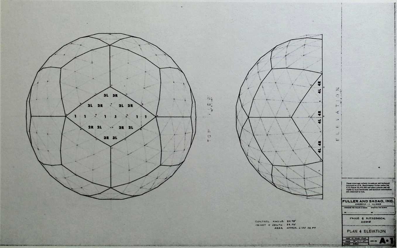
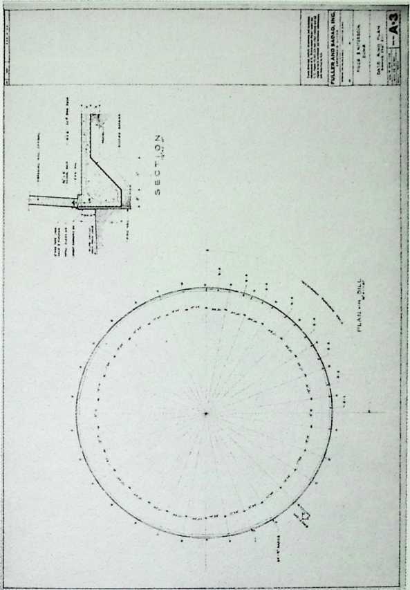
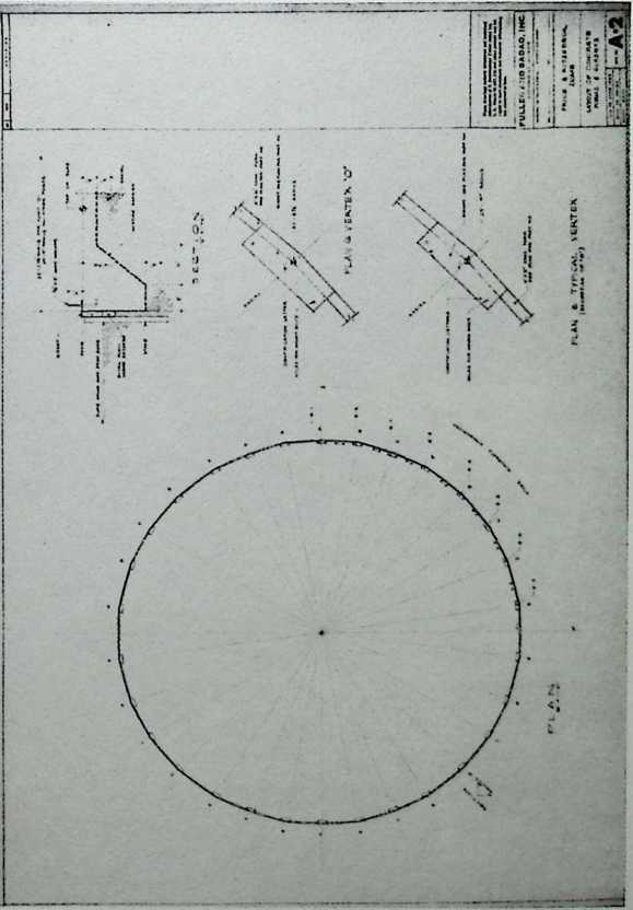
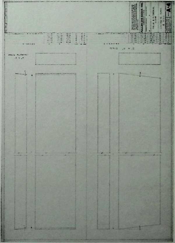
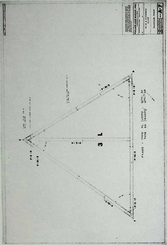
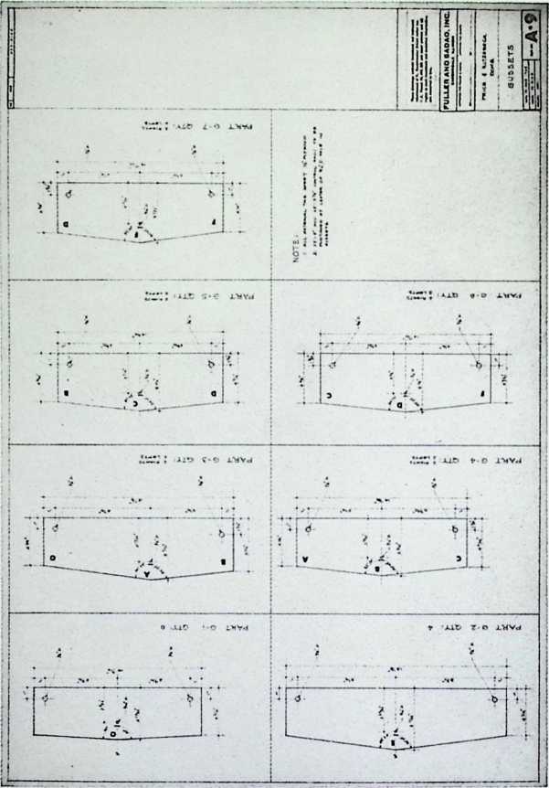
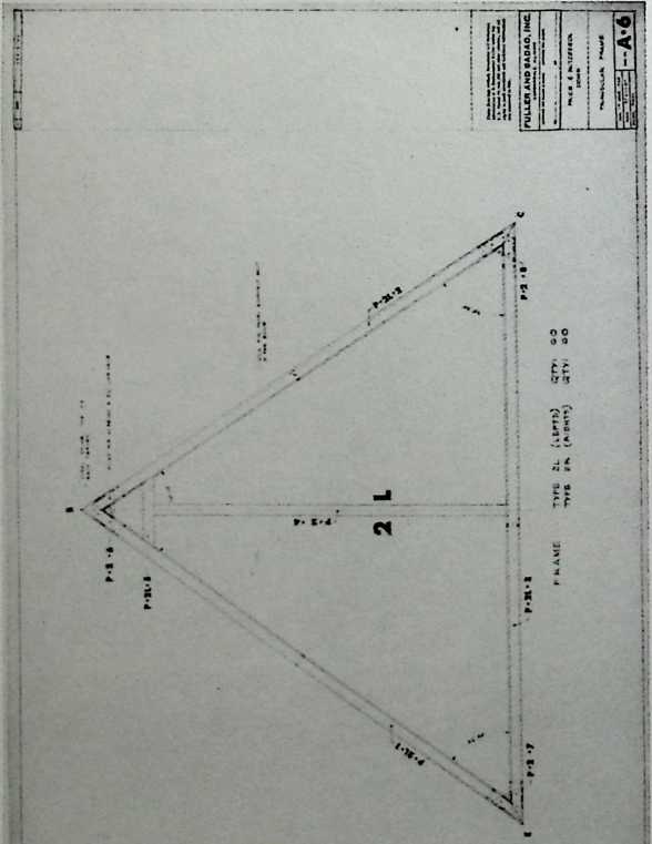
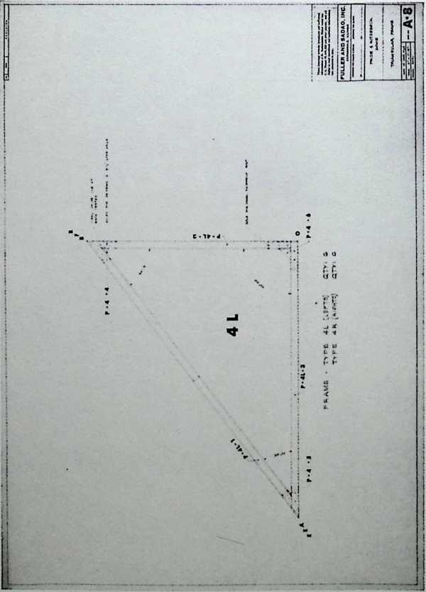
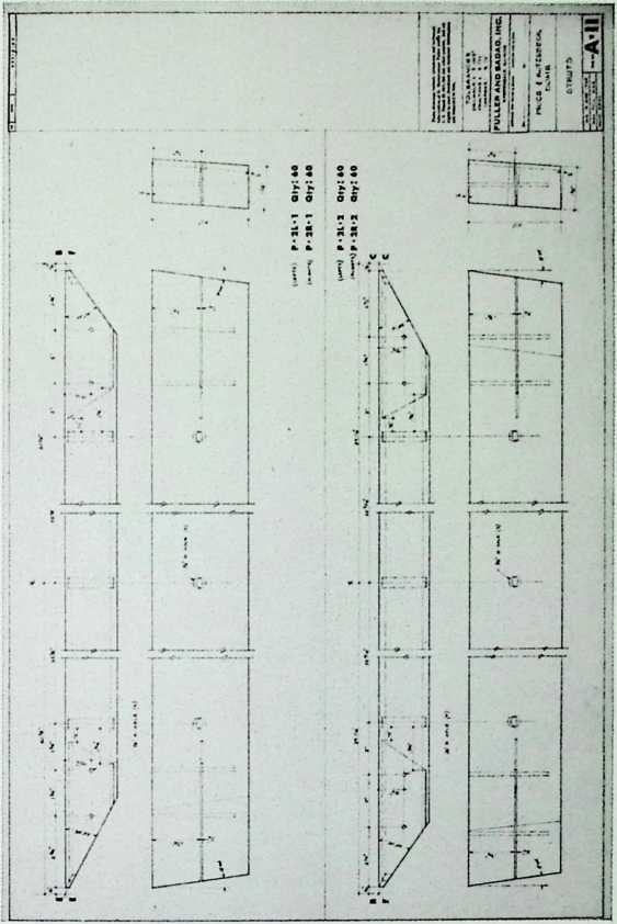
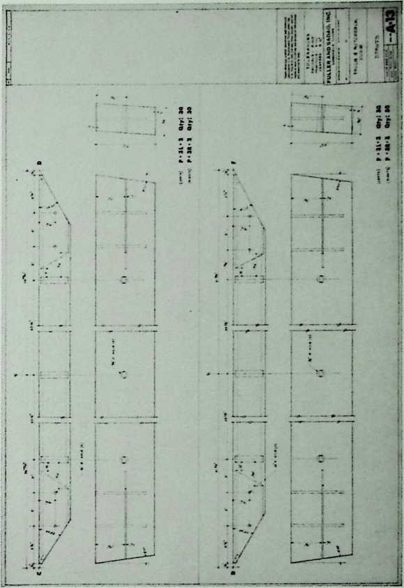
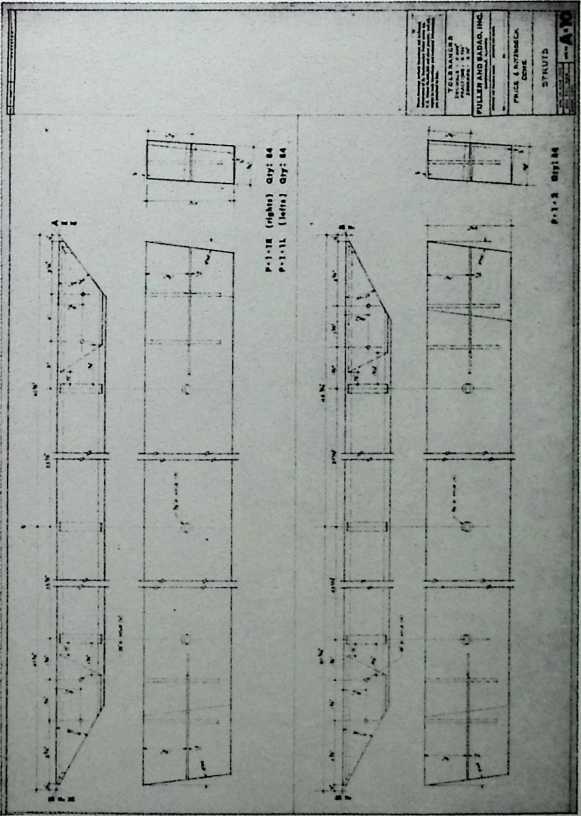
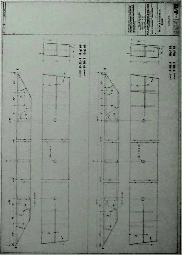
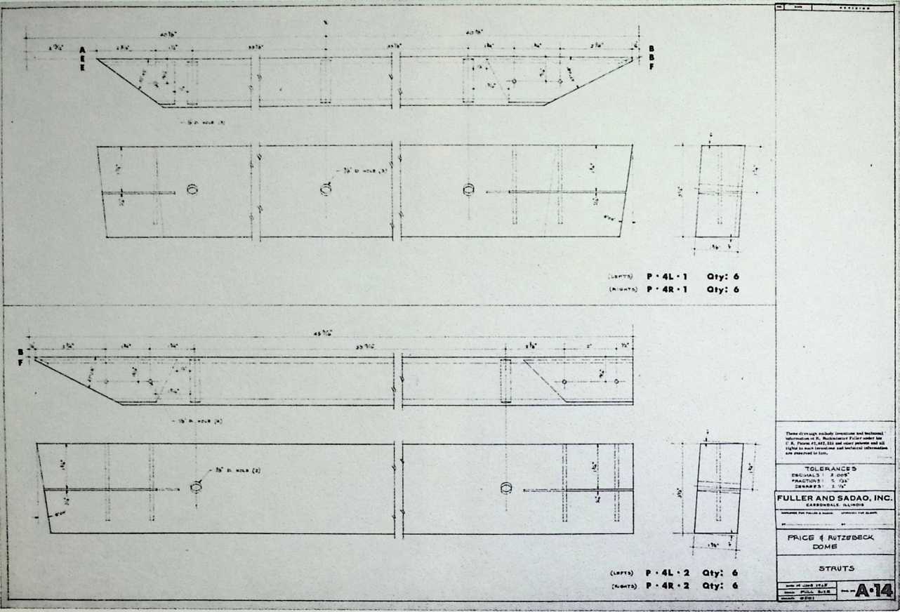
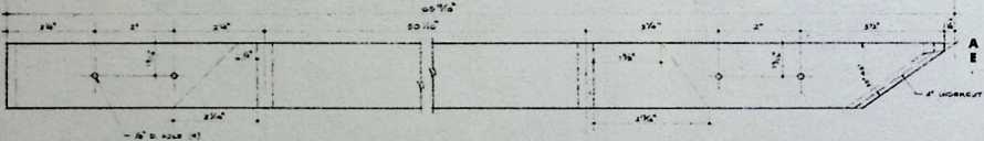
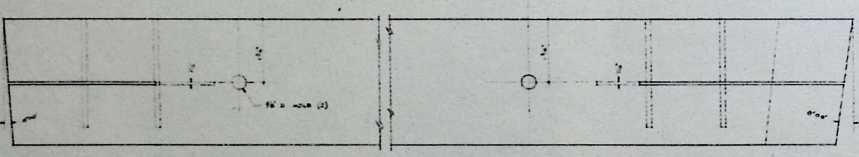
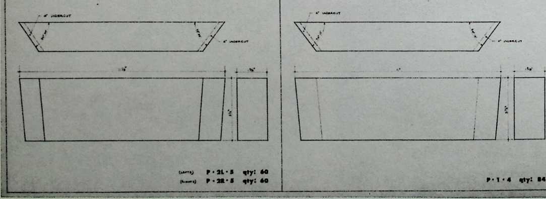
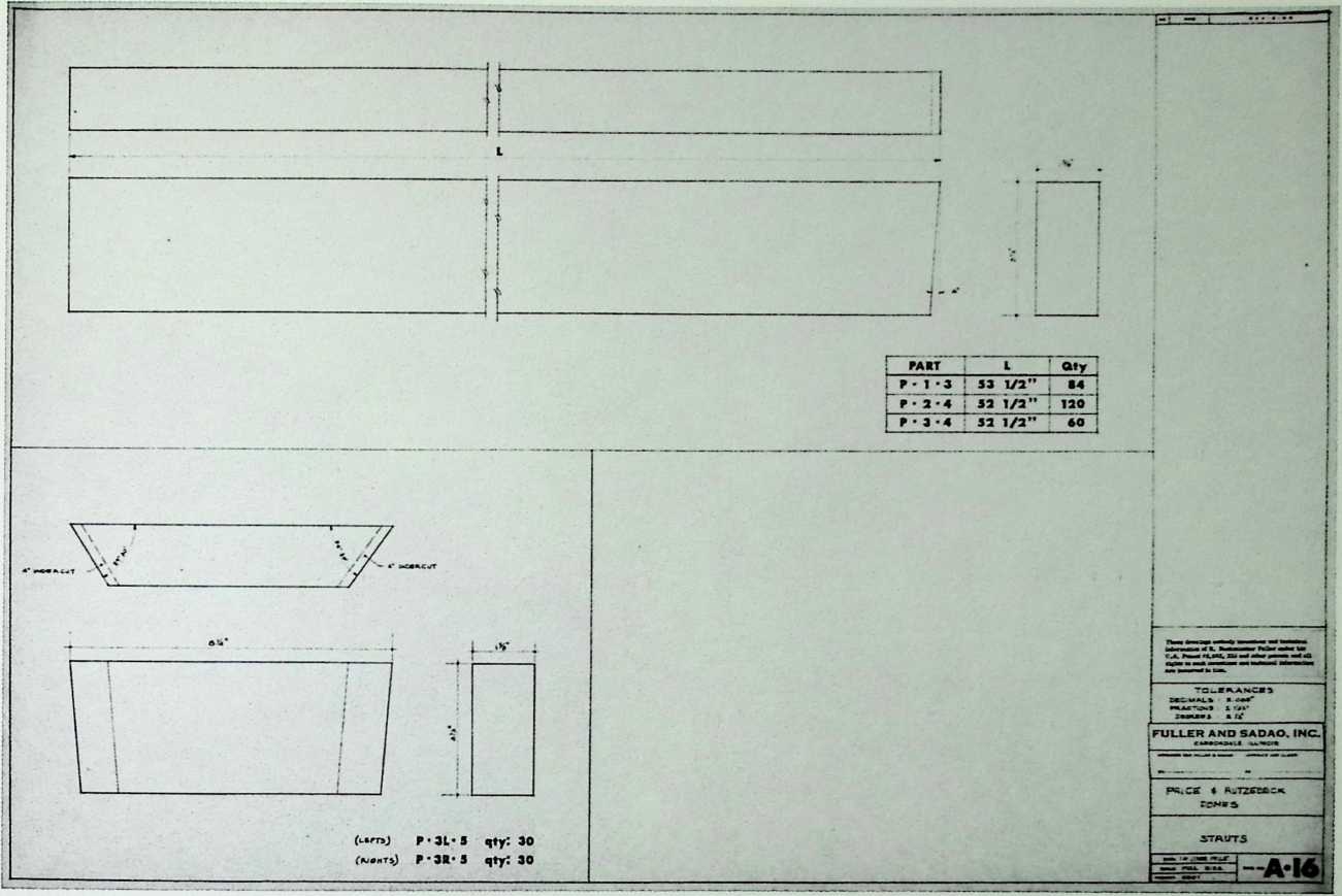
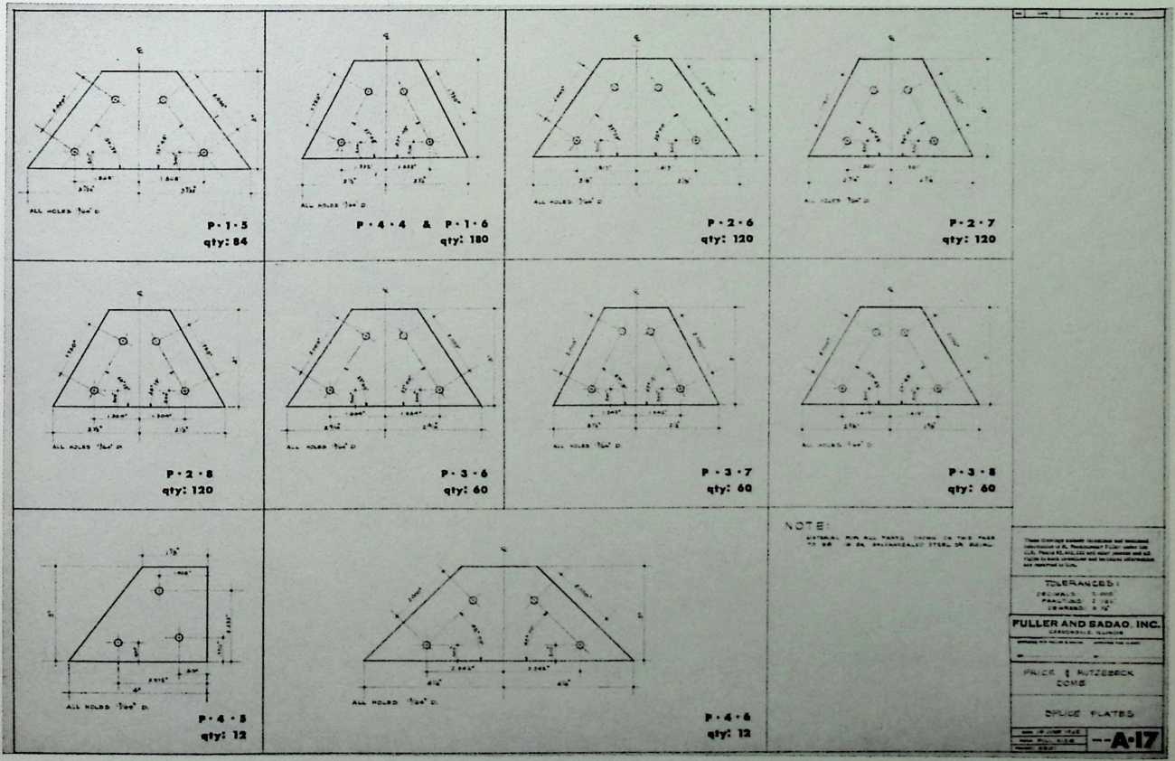
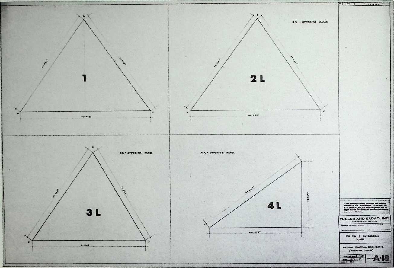
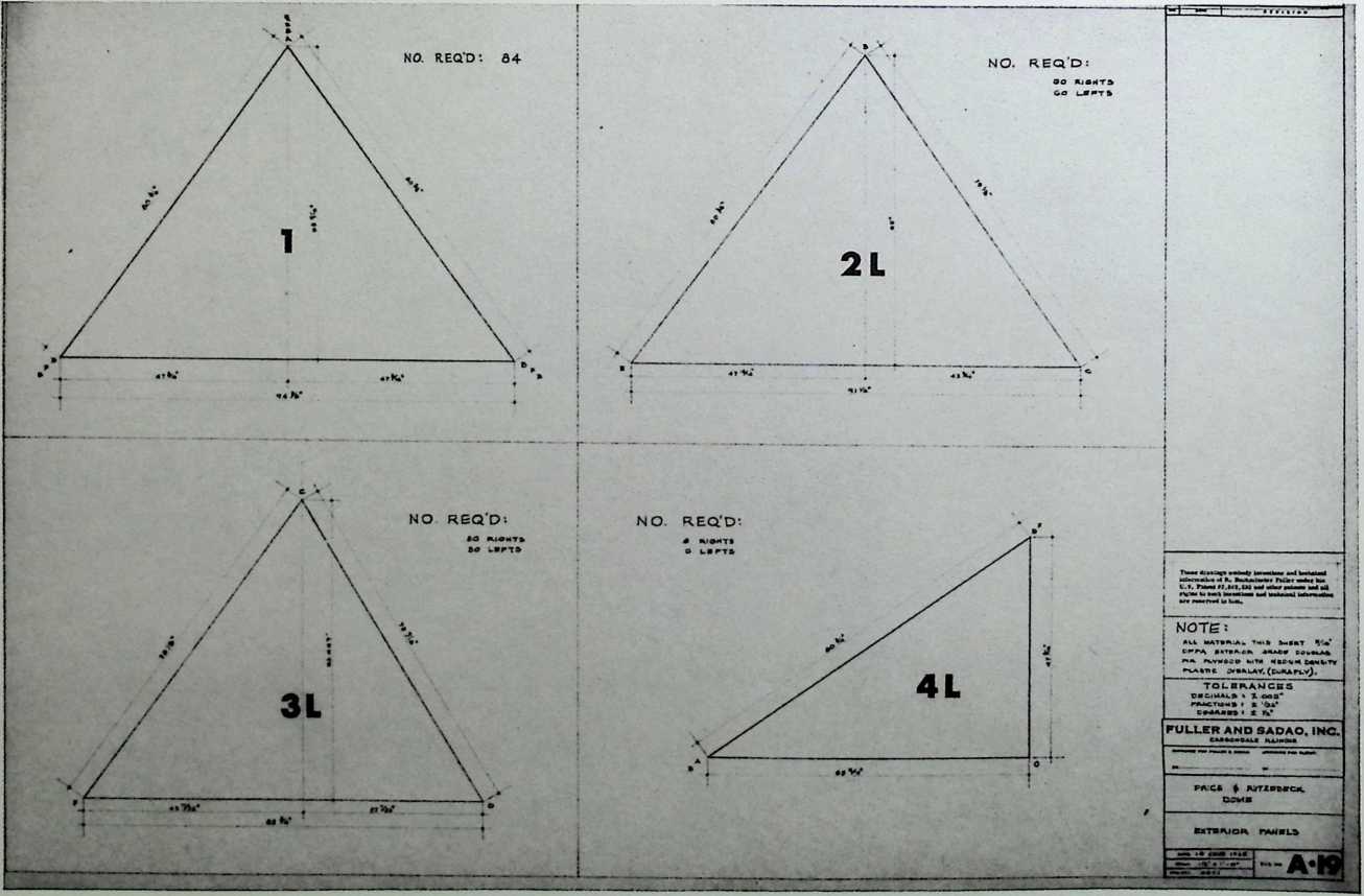
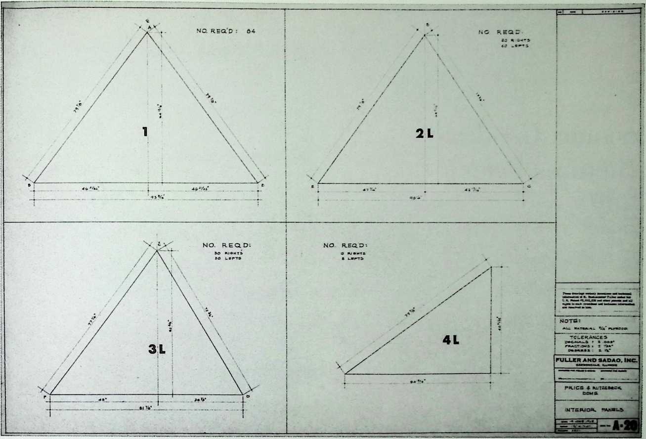
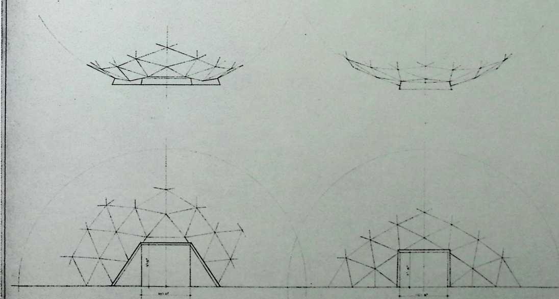
¶ Chapter 16 Price and Rutzebeck Dome Fuller & Sadao, 1965
The radius of this dome was specified as 29.75 feet, and it was to be 29.75 feet high. It would have had two shells with a fiberglass insulation and two types of triangular frames, the smaller of which fit the ground line. The double layer of exterior grade Douglas fir plywood is covered with a medium-density plastic, making it waterproof. Also intended for mass production, this dome was designed with two types of doors: one small and square; one large and rhombic.
![]()
Qty: 6
Qty: 6
![]()
![]()
ALTERNATE DOOR DETAiLS
FULLER A??D SASAO. INC.
¶ Chapter 17 Monohex Geodesic Structures Patent 8/31/65
The monohex was conceived earlier as one manifestation of the radome. It is composed of molded polygonal sections, the corners of which can be cut to form circular windows when assembled to adjacent panels.
![]()
Aug. 3, 1965
Filed Dec. 19. 1961
R. B. FULLER
GEODESIC STRUCTURES
3,197,927
6 Sheets-Sheet 1
Aug. 3, 1965
R. B. FULLER
GEODESIC STRUCTURES
3,197,927
Filed Dec. 19. 1961
6 Sheets-Sheet 2
ItII**(Edo** 3
INVENTOR.
RICHARD BUCKMINSTER FULLER
Aug. 3, 1965
Filed Dec. 19, 1961
R. B. FULLER
GEODESIC STRUCTURES
3,197,927
6 Sheets-Sheet 3
Aug. 3, 1965
Filed Dec. 19. 1961
R. B. FULLER
GEODESIC STRUCTURES
3,197,927
6 Sheets-Sheet 4
![]()
Aug. 3, 1965
Filed Doc. 19. 19S1
R. B. FULLER
GEODESIC STRUCTURES
3,197,927
6 Sheets-Sheet 5
Aug. 3, 1965
Filed Dec. 19. 1961
R. B. FULLER
GEODESIC STEVCTUEES
3,197,917
6 Sh««tB-Shwt 6
ITnosoIlS
![]()
![]()
I HIH
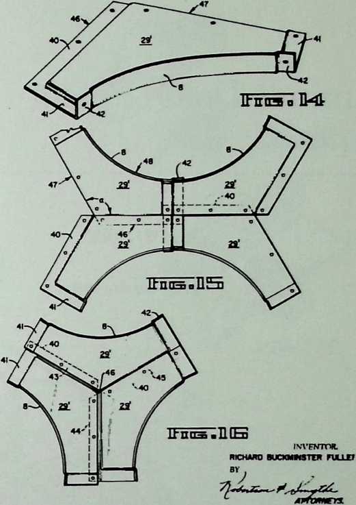
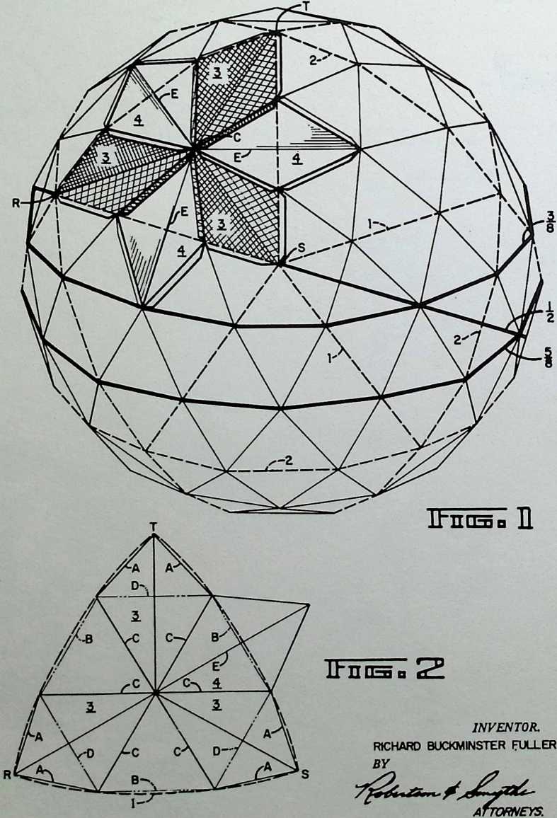
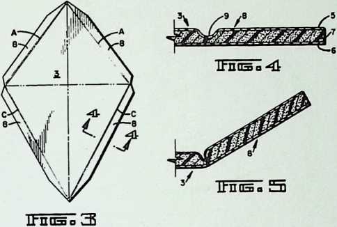
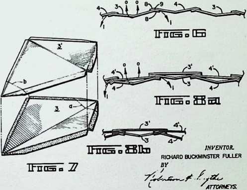
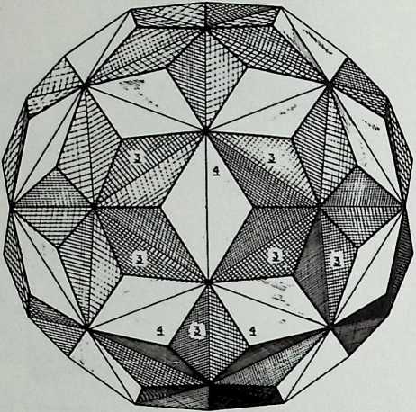
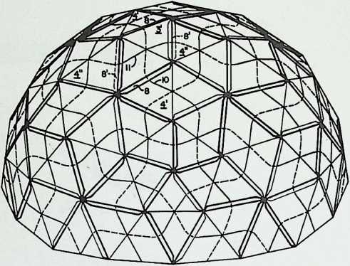
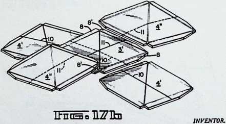
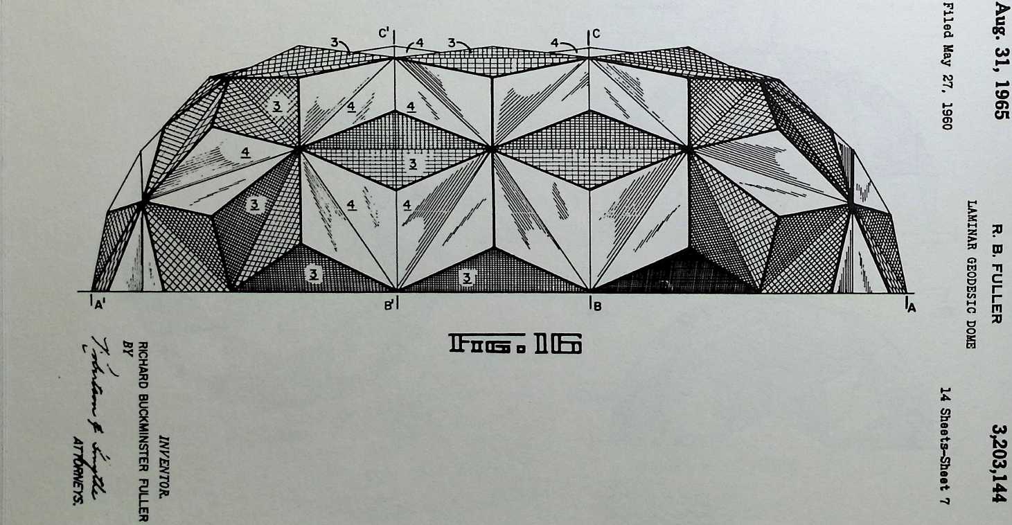
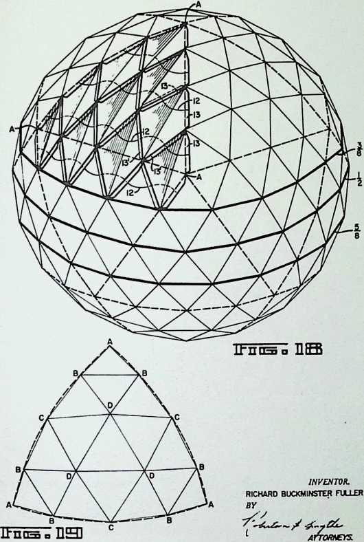
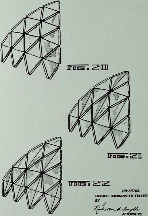
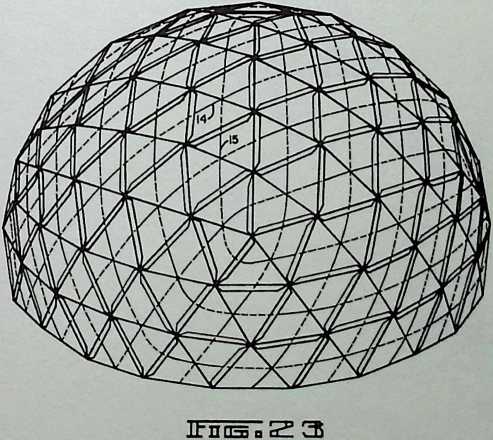
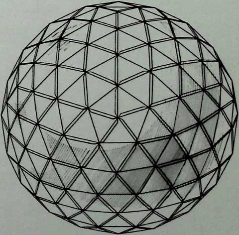
Laminar Dome Patent 8/31/65
The laminar dome can be fabricated of aluminum, plastic, paperboard, or steel diamonds. These are bent along the shorter axis and connected to other diamonds along their eccentric flanges.
Aug. 31, 1965
3,203,144
Filed May 27. 1960
R. B. FULLER
LAMINAR GEODESIC DOME
14 Sheets-Sheet 1
Aug. 31, 1965
Filed way 27. 1960
R. B. FULLER
LAMIHAR OEODESIC DOME
3,203,144
14 Shaate-ShMt 2
Aug. 31, 1965
Filed Hay 27, 1960
R. a FULLER 3,203,144
LAMIHAR GEODESIC DOME
14 SbeeU-She.t 3
Aug. 31, 1965 r. B. fuller 3,203,144
LAMIHAR OEODESIC DOME
Filed May 27. 1960 14 ShMt»£ll„t 4
Aug. 31, 1965
Filed May 27. 1960
R. a FULLER
LAMINAR OEODESIC DOME
3,203,144
14 Sheota-Sheet 5
cdM
ITHOSo 112
irnas» H-4
INVENTOR.
RICHARD BUCKMINSTER FULLER
INVENTOR.
RCHARD BUCKMINSTER FULLER
Aug. 31, 1965 r. b. fuller 3,203,144
LAMINAR GEODESIC DOME
Filed May 27. 1960 14 Shoet»-5hoot 6
Aug. 31, 1965 r. b. fuller 3,203,144
LAMINAR GEODESIC DOME
Filed May 27. 1960 14 Sheots-Sheet 8
irncs. 115
INVENTOR.
RICHARD BUCKMINSTER FULLER BY
RICHARD BUCKMINSTER FULLER
![]()
![]()
![]()
Aug. 31, 1965 r. b. fuller 3,203,144
LAMINAR GEODESIC DOME
Filed May 27. 1960 14 Sheeta-Sheet 9
Aug. 31t 1965
Filed May 27. 1960
R. a FULLER
LAMINAR GEODESIC DOME
3,203,144
14 Sheet>-Sheet 10
Aug. 31, 1965
Filed Hay 27, 1960
R. B. FULLER
LAMINAR GEODESIC DOME
3,203,144
14 Sheets-Sheet 11
Aug. 31, 1965
Filed May 27. 1960
a B. FULLER
LAMINAR GEODESIC DOME
3,203,144
14 Sheets-Sheet 12
lbnos« 241
INVENTOR.
RICHARD BUCKMINSTER FULLER
BY
INVENTOR.
RICHARD BUCKMINSTER FULLER
BY
Aug. 31, 1965
R. B. FULLER
3,203,144
LAMINAR GEODESIC DOME
Fll«4 May 27. 1960
14 Sheet»-Sl>…t 14
Aug. 31, 1965 r. a. fuller 3,203,144
LAMINAR OBODB3IC DOME
Filed May 27. 1960 14 ShaaU-Shaat 13
INVENTQR.
RICHARD BUCXMWSTER FULLER BY
v ATTORNEYS.
¶ Chapter 18 Octa Spinner Patent Application 1965
The Octa Spinner is a machine that bends sheet metal into stiff octahedrons that can be fashioned into an octet truss. Because of the expense and time involved, Fuller never pursued his application and never secured a patent for the Octa Spinner.
INVENTOR.
RICHARD 8UOMNSTER FULLER
![]()
INVENTOR.
INVENTOR.
![]()
![]()
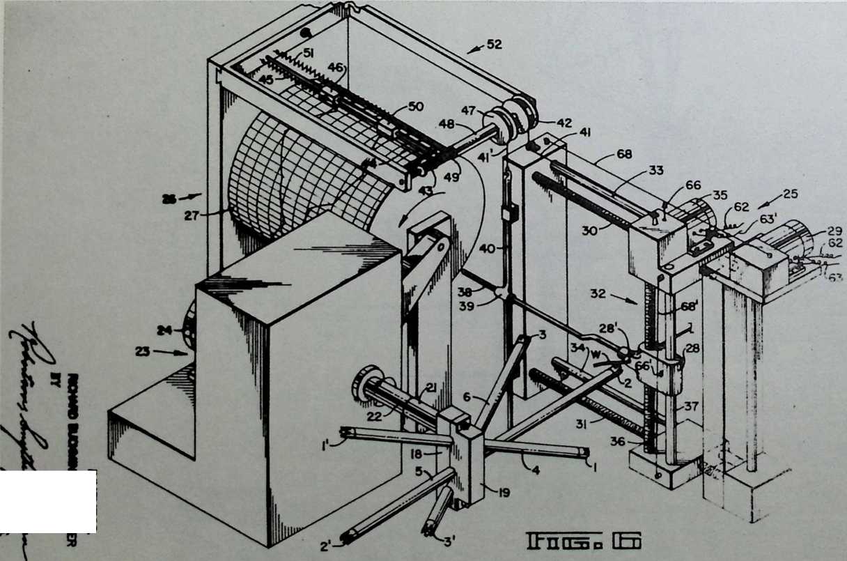
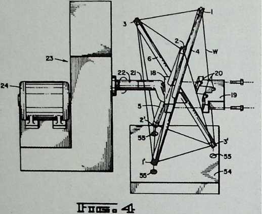
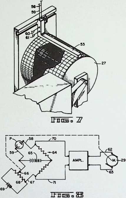
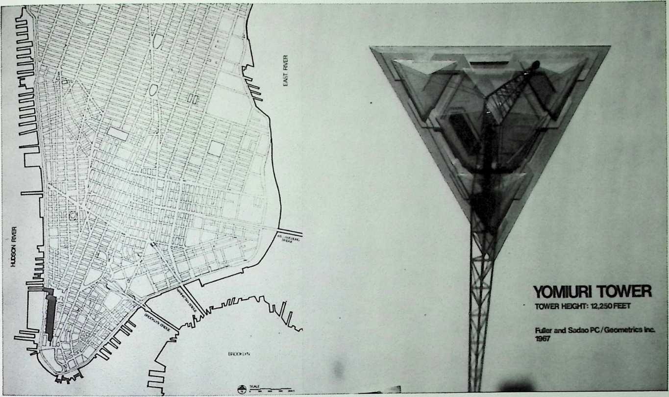
¶ Chapter 19 Yomiuri Tower, Japan Fuller & Sadao, 1966
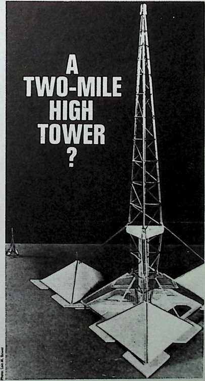
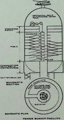
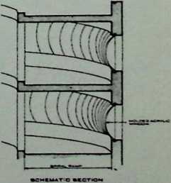
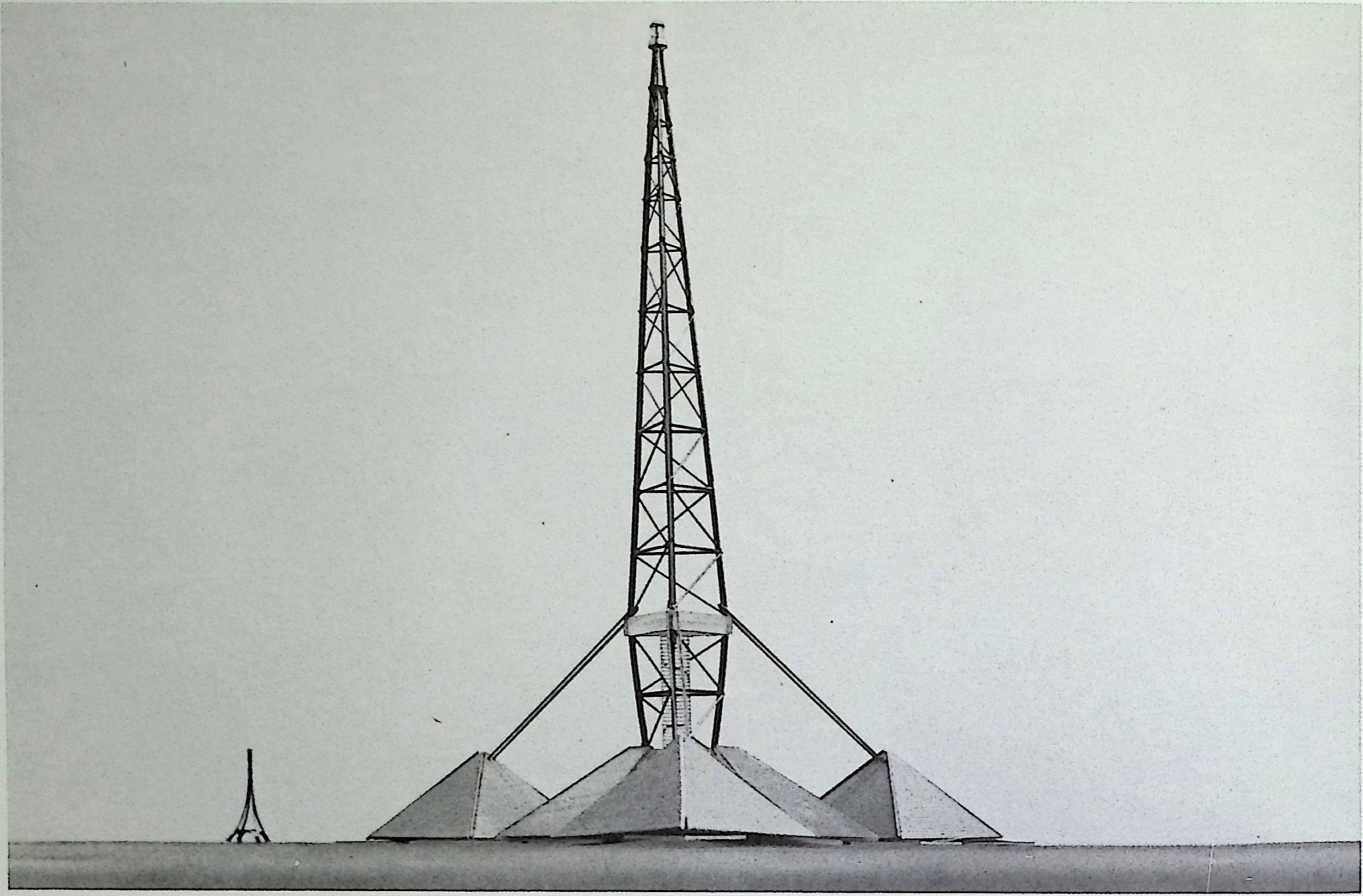
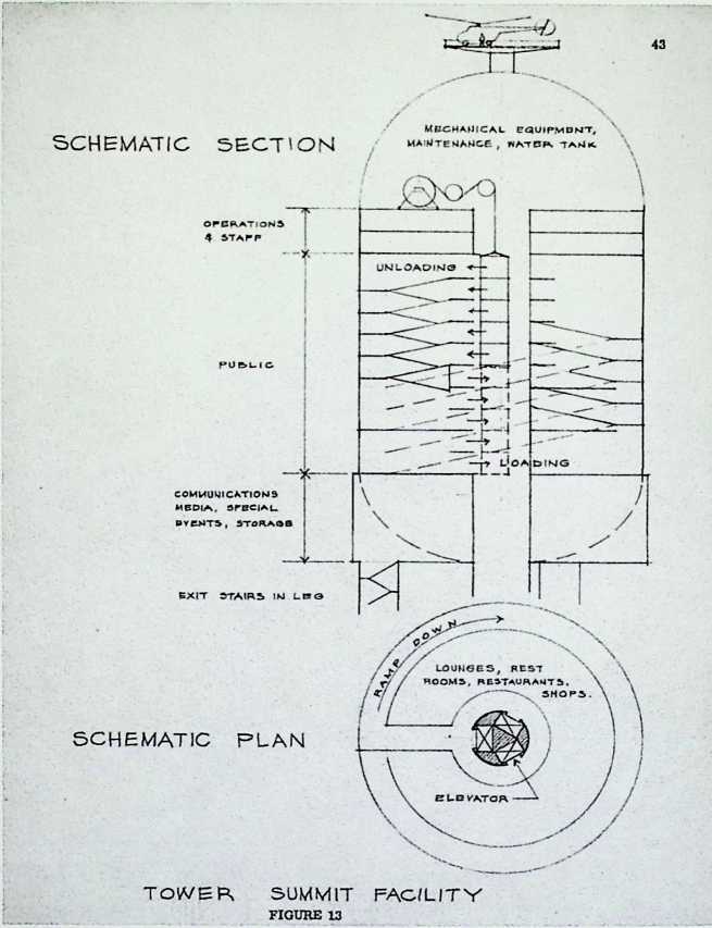
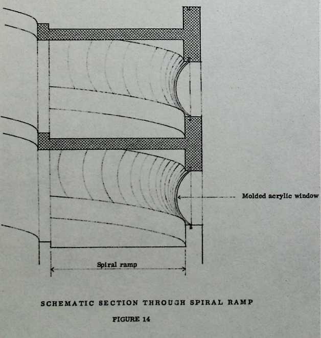
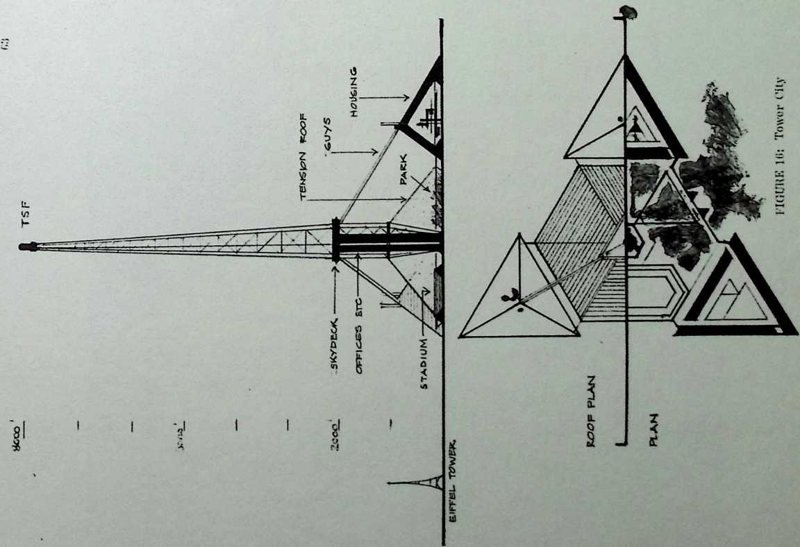
The impetus for the Yomiuri Tower was to erect a structure higher than the summit of Mount Fuji. It would have been 12,300 feet high if it had been feasible to construct. Originally planned as a large tenseg- rity mast on three legs, the Yomiuri Tower would have had an observation pod of over thirty stories at the top with plexiglass windows providing a 360° view of Japan and the Pacific. Subsequent studies proved that such a tall structure could not withstand the force of the winds at high altitudes, and six guy wires were added to the tower’s lower third. These guy lines were to be anchored by three vast tetrahedral feet (containing housing), each of which would have been much larger than the Eiffel Tower. Offices built into the base of the tower mast would have been twice as high as the World Trade Towers in New York City. In order to maximize the use of the real estate, a stadium and covered park were also planned to be fit into the hexagonal lot at the base.
The problems that defeated this project were many, but chief among them was cost. As a tower two miles high, the Yomiuri project would have cost over SI.5 billion, which was six times the original estimate. When the project was redesigned to be roughly half as tall, the expense was reduced drastically, but the diminished height of the tower would have countermanded its original function. Another problem would have been the acquisition of the real estate necessary to contain the elaborate structures of the tower's base. Moreover, the dangers of ice sherds falling from thousands of feet called for intermediate shelters above the buildings on the ground.
If the tower were erected, it would immediately become the world’s tallest building, offering impressive views from pressurized lounges, rest rooms, restaurants, and shops.
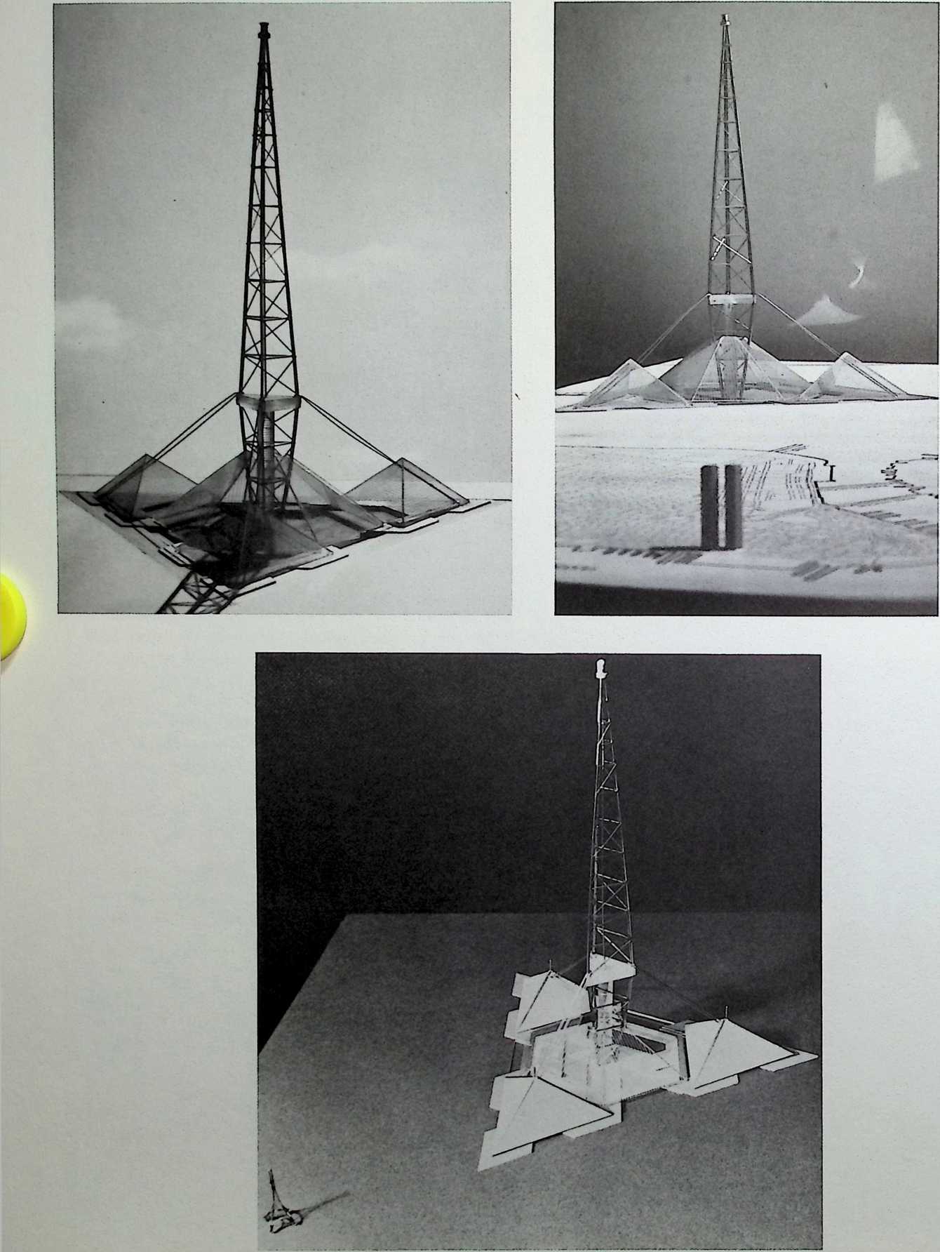
Tower studies proved construction technically possible (scale model photo shows Eiffel Tower in background) but economically unfeasible.
An entrepreneur from Japan presented a trio of design firms with a proposal for an observation tower to tall that. If it were built, would certainly discourage any other* with the ambition to own the world'* tallest anything. If. Indeed, it would not extinguish their hope* altogether. The objective of the structure envisioned was to provide an observation point that would overtop Mount Fuji, which, at 12489 It above tea level, it the highest point on the island of Hon«hu. For the tile selected. thia would have required a structure that iltclf would be 12450 ft high, just over two mile*.
The scale of the tower contemplated exceeded the boundaries of known structural parameter* *0 far a* to require the eonvuliant* to prepare a 100-page report jutl to decide whether it wa* practicable to prepare a feasibility study. The answer was no. but. In arriving at that answer. they uncovered some relationship* between height, co* I, and life al the top that are interesting In themwlret. and. Incidentally, may shed some light on any schemes planner* may have for buildings substantially taller than the 100-story structures now under construction.
Among the problems faced by the designer* that arc not normally encountered in the design of building* or even, for that matter, tall tower* of the «ire that have been built to date were: king, high wind*, high ratio of structural weight to load* supported, and the need for pressurisation of the occupied space at the topi
From the best available data, the designers were forced to assume that all structural member* might accumulate a* much a* 12 In. oi ice; moreover, in any latticelike arrangement of structural members, apace* between member* lesa than 5 ft apart would have to be considered'M completely plugged with ice. Not only would the ma** of iee add substantially to the gravity load Imposed on the tower and it* foundation; the encrusted ice would also increase the effective area exposed to wind, and because of It* rough surface, the drag coefficient would be in* rrrased, too.
Exact data on wind velocity at the cleva- tioo tonirmplated wa* not available, but the designer* suspected it might possibly be at high a* 300 mph. The effect of high wind velocity at high altitude* is offset somewhat by the lower density of the air at thowi elevations. Nevertheless, the la- feral force* imposed by wind loading became ‘‘the tingle most Important determinant of (the tower**] safety and economy,’’ according to the engineer*.
FOR NOW, FORGET IT!
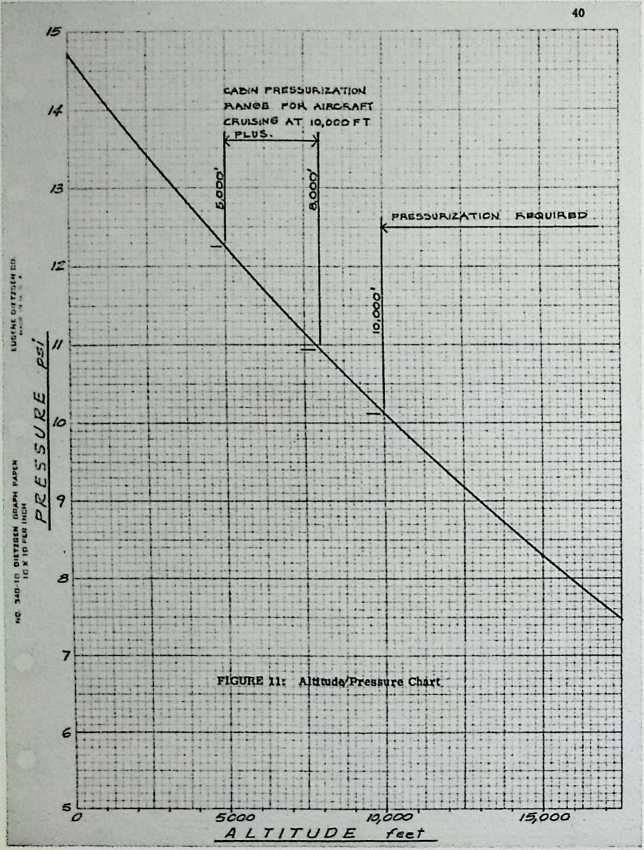
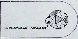
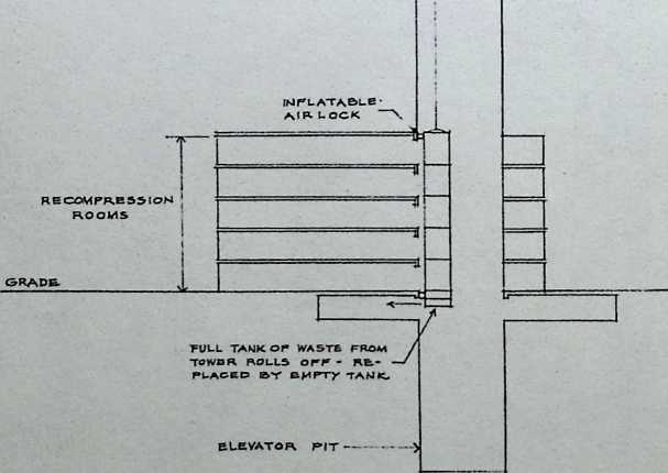
For the comfort of mc«t airline passenger*. and for the very health and wellbeing of some, the cabin* of mo*r aircraft miL*uig at altitudes alwe 10.000 fl are pre-»urired to roeretpr.nd to an altitude of between 5000 and 8000 ft — about 10 psi. Similarly, the pod atop a 12450-ft tower would require pressurization. a* would the elevators serving the pod.
Quite aside from the problem of providing air locks for the elevator doors at both lop and bottom terminals pre-sur- izalion of the capsule at the top of the tower add* considerably to the structural requirement* of the shell of the capsule. The negative air pressure induced on the leeward side of the ca|»ule at de-ign wind velocity, when added to the positive internal pressure, would create unit pre— sum of TOO to 800 psf. much higher than the unit pressure* encountered by conventional building wall systems.
Indeed, the design of the occupied observation and recreation foiiluy planned for the top of the tower would net be unlike the design fur an aircraft fuselage intended for cruising al 300 mph al an altitude of 12450 ft. Unlike an aircraft body, however, the tiny, porthole-like window* that serve well enough in airplane* would be wholly untuitable fur an observation tower, since a wide, unobstructed view of the *urrvundiag country side would have to be one of the lower'* mo*l irnjwriant feature*.
Structure
Two types of configuration* were considered: a free standing tower and a guyed structure. Also, two constructional material* were considered: type T-l steel (minimum yield point 90.000 psi), and type 7075-T6 aluminum (minimum yield point 60.000 psi I.
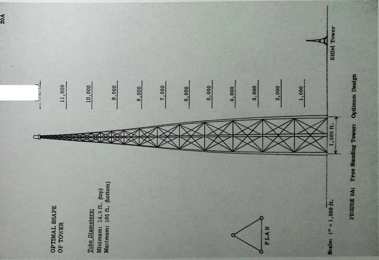
- Free-standing tower cucfiguralian with three hollow leg* with tubular heriicn- tai and diagonal was selected as having the best potential for further study by structural optimization.
- A computer program was developed to assist optimization of dimension* and weight for abuse free-standing tower 1 onfiguration.
- Computer pregram permitted cpt iniza- turn of weight and dimension* and substantial study of parameter* such as magnitude of wind load, weight supported at top. and height of tower.
- A similar approach was used for guyed tower. Basic configuration with three set* of guys one al each of three comer* uf triangular central tower. A computer program wav drvel.'ped to determine the optimum guy slope, the optimum number of guy level*, and weight of structure.
Frw-SUnding Canliltvor
The must evvnomkal free-standing tower 12450 ft high turned out to be a three-legged structure with hallow. circular leg* spaced about KXN ft apart al the base. It would weigh about 3200 culLcn lb, which, at an estimated coat oi 1500
jut 1000 lb nf erected Merk would I* >1600 millixi (excluding foundation*). vrry mu< b m>>re than the 1500 million the sponsor of I lie project had originally rnvi*iwwd. ( A similar tower of aluminum would weigh about 30 per rent les*, licit tlx erected ris-t nf aluminum i* nrarly . twice- Hut of steel.) Curve* l-hetrd from the nunpuler |<rintcct* show Imw extremely sensitively the Ictal weight, and hence the 1 o>t. of the structure read* Io relatively -mall changes in the design parameter*. Uy cutting the height fnm 12450 ft to 10.000 ft. the weight of the structure dru;v by 46 per vent. Changing the arbitrarily assigned wind velocity frern 300 tn;i!i to 200 mph < nt* lice weight by 61 jier reel.
Stayed Mast
An analyse* of a guyed tower 12450 fl high di-*lu-ed that this configuration luuld dranuti ally reduce lite weight of the required structure. The optimum de- .!g3 would weigh ju»t 700 million Ih. just under 22 per cent of the comparable free-landing tower. Of the 700 million lb. the shaft accounted for 570 million Ih. at an estimated $500 per 1000 lb erected. acai the guy cable* fur 170 millinn lb at >750 per 1000 lb erected, a total of $100 million (excluding foundation*). which uf course i* much cfo-er to the »pcnsee'* original expectation.
However, the longest of each of the three *et* of guy wires (spaced 120 ft apart! would have reached out ever 10.000 ft fruzn the bate of the matt. The vast amount uf land beneath the three »et* of guy wire* poed a severe problem; tn acquire the land outright would be costly, and it is doubtful if acquiring air right* ak-ne would be practical in view uf the hazardous condition* that would o.cur under the cable* whrn they shed accumulated ice during a thaw.
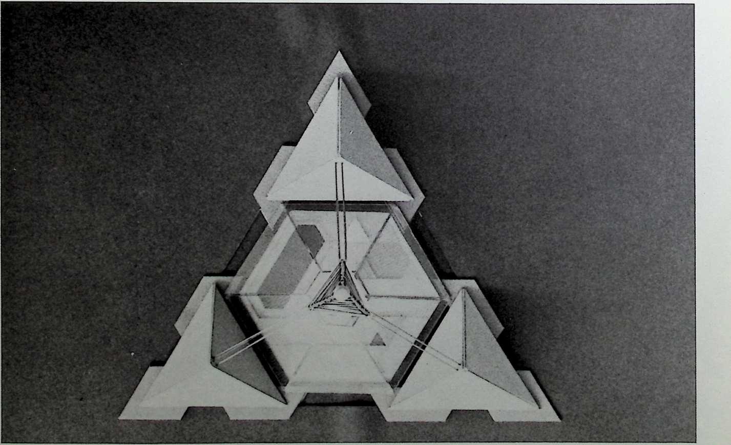
Since the guyed tower with it* attendant real estate problem* exceeded the <ci»l fur which the vpca*ur wo* prepared. the designer* proposed an al- tentative. They recommended an 8000-ft. semi-guyed structure, a mudel of which i« illustrated. Linulmg the height to ft eliminated the need for pre»surixati=a; by adding three massive structure* around the l>a«e of the mast, the designers nut only provided solid anchorages fur the short guy* that stay the lower section of the lower, they al*o generated space that could l< turned to revenue- |ctudu> eng activities that would help to amurtire the io*l of the tower.
Because the (rebminary study ruled out the cvom-mic fca>:bcLty cl extending the tower above the height of Mount Fuji, the *|*«sur felt tbit the project would base sacrificed it* greatest (vienlial for attraiting visiter*; the project i» now indefinite Is deferred.
Partis ipaUng in the study were; Fuller-Sadao Gcumctrw*. arc helot* and engineer*; and Sunpsvo. Cuabrrtz A Heger, la., consulting engineer*.
n«vtMaLa 1*: r.a
MVDCIU IM r/a
.< Two- VJe Hcgi r,u<r ’ fc, Auar, It! XS7

12,000
47
45
SCHEMATIC
A N
SCHEMATIC SECTION
BASE OF ELEVATOR SHAFT
FIGURE 15
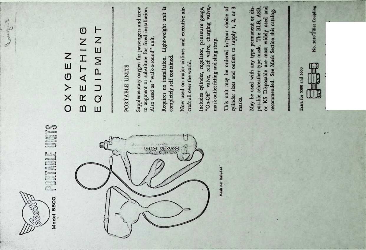
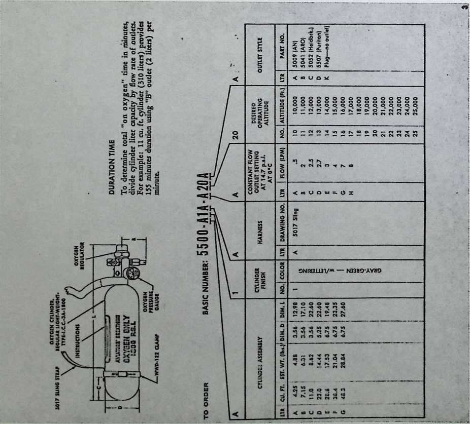
Connects portable to recharging source.
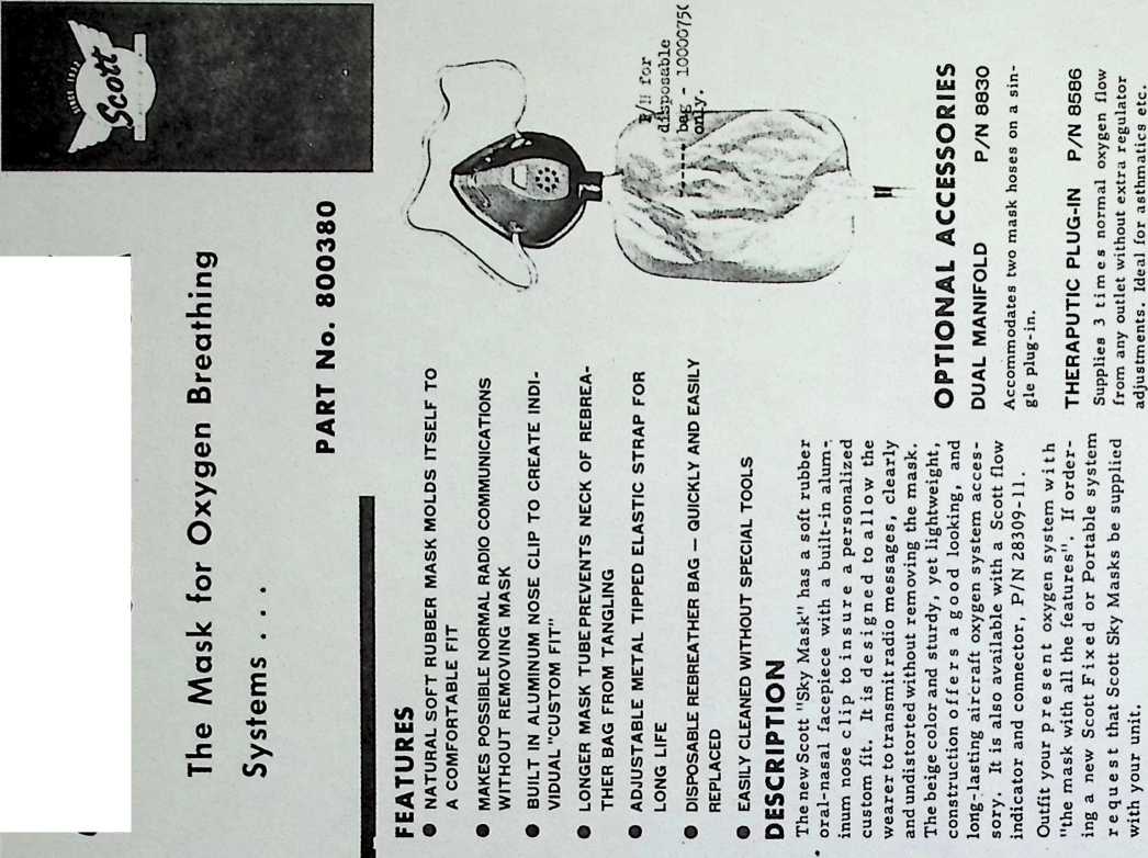
SKY MASK
SCOTT AVIATION CORPORATION O LANCASTER, NEW YORK form No. 1442 9-65SAC 5m Printed in U S A.
‘‘Worthington, Ilk* lome manufacture r», may permit higher ipeedi and dliplacemenli, after engineering review of ionic* condition!.
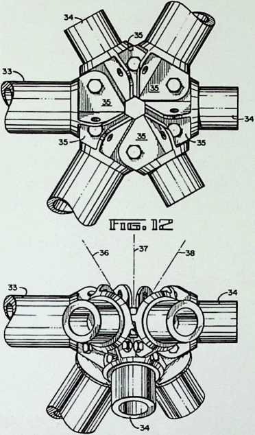
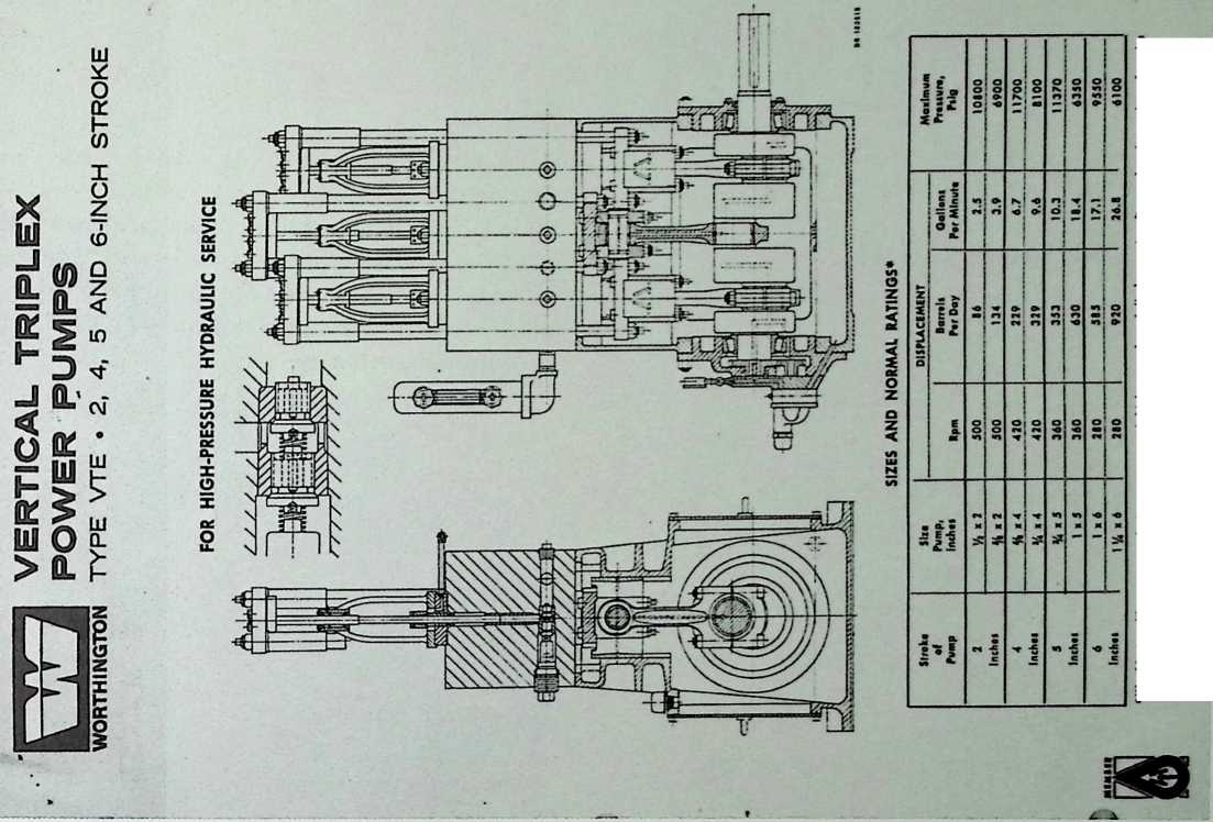
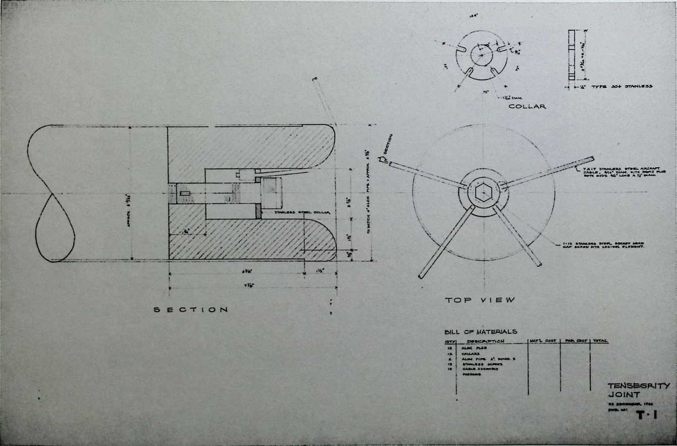
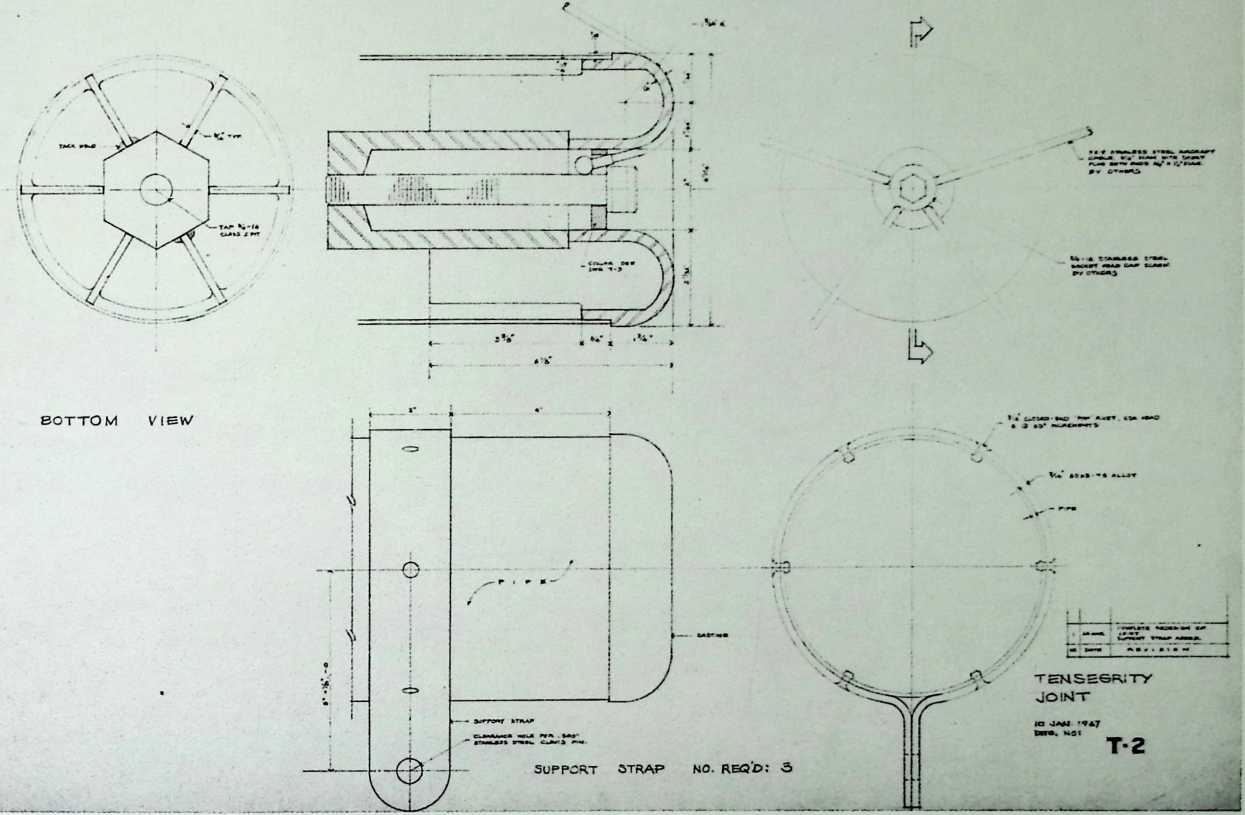
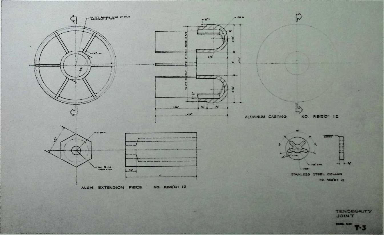
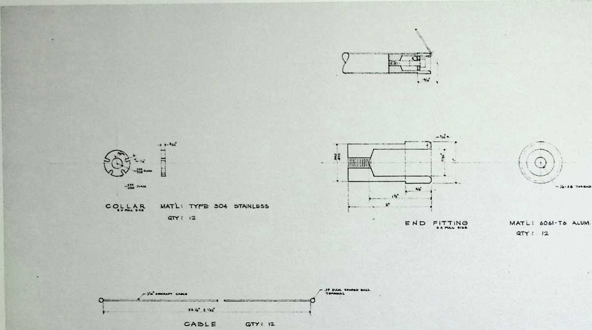
¶ Chapter 20 Tensegrity Joint Fuller & Sadao, 1966
Attending the patents of aspension structures, Fuller designed this tensegrity joint with the architect Shoji Sadao. This design fulfilled the need for a device that would make the pipe ends and cable anchors both precise and more durable. The tensegrity joint is indispensable for a structure that is required to last longer than an exhibition.
£ strut
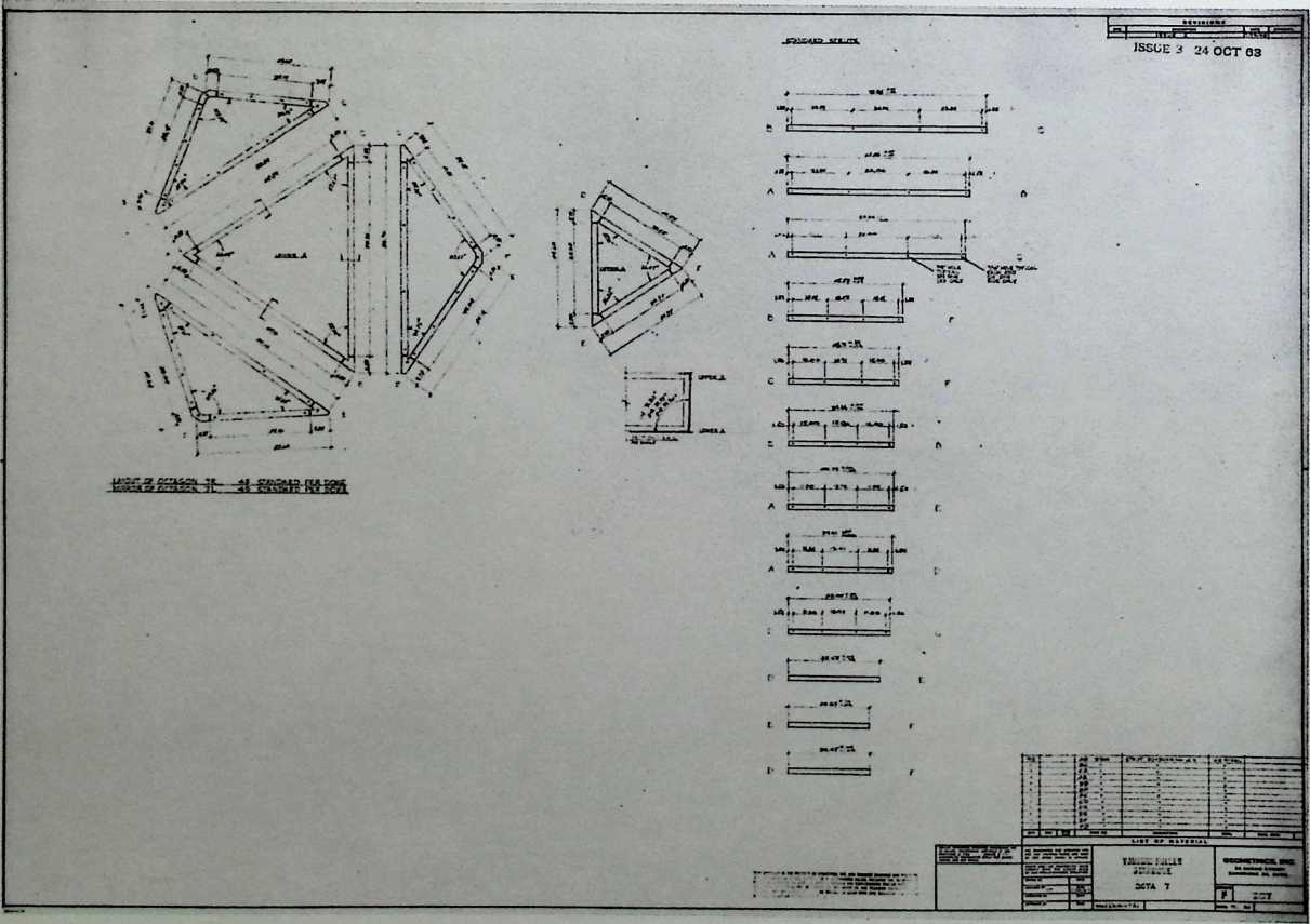
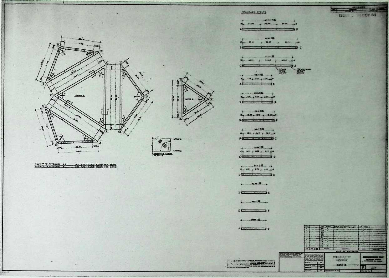
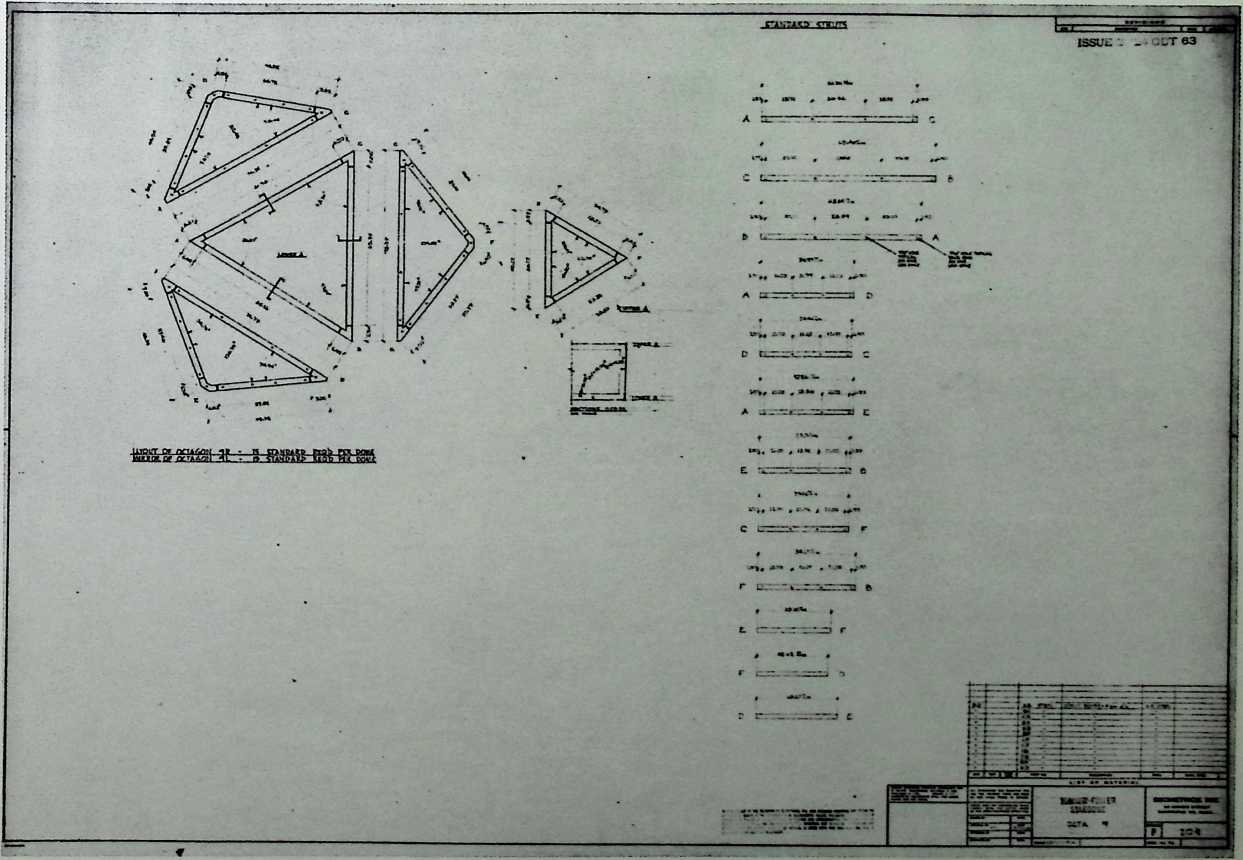
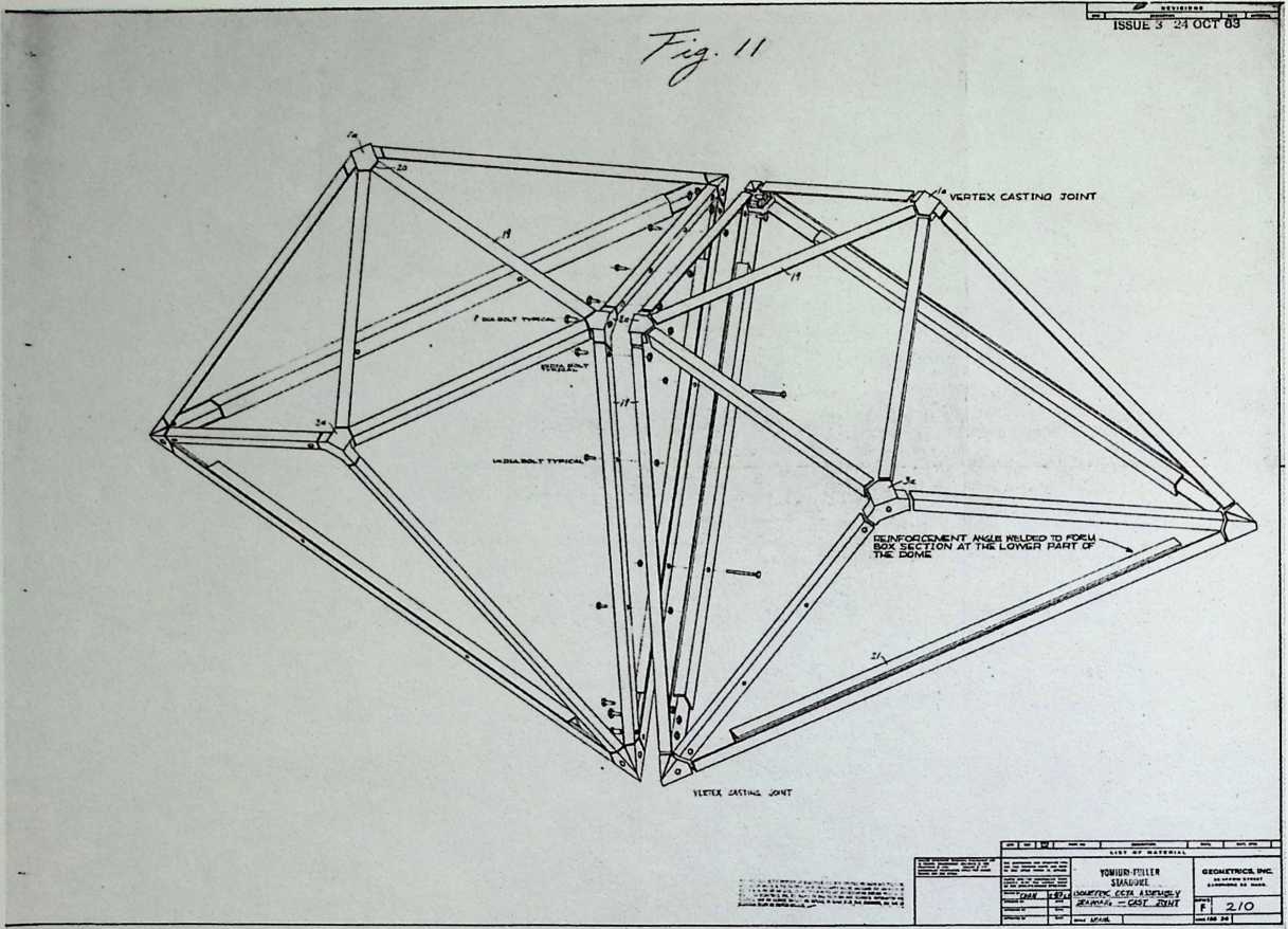
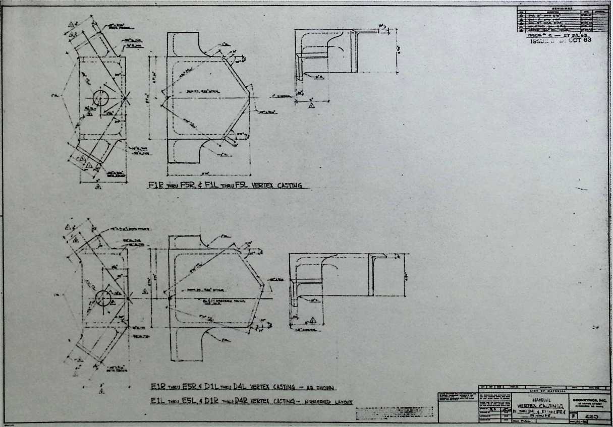
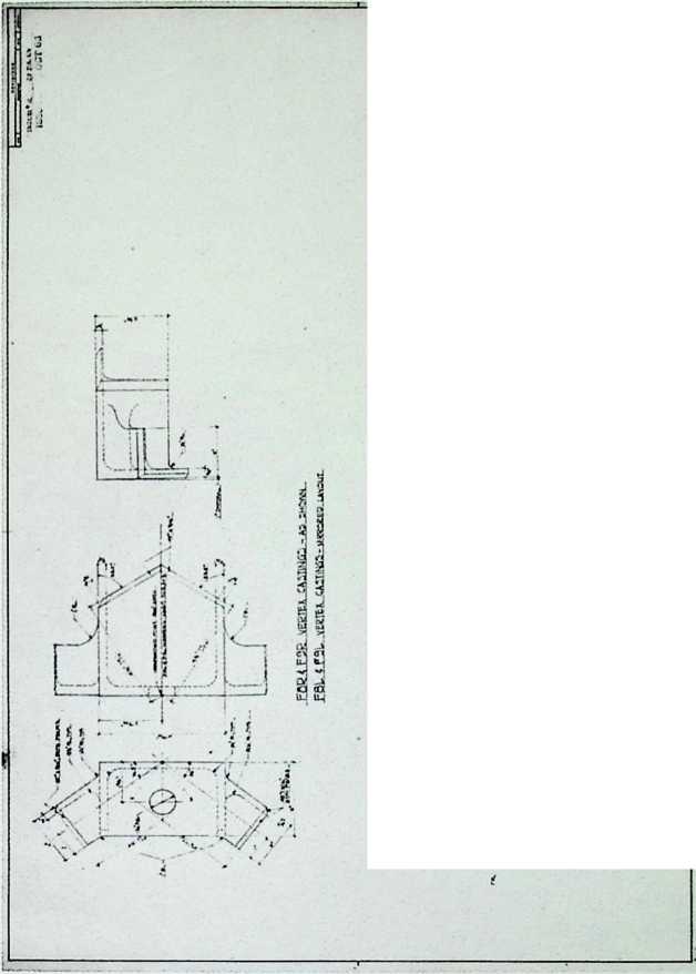
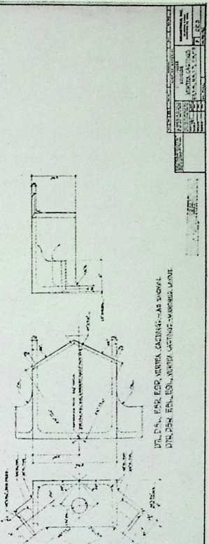
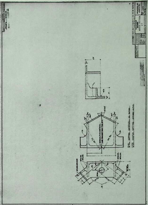
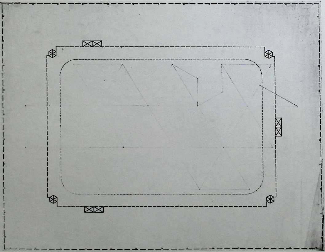
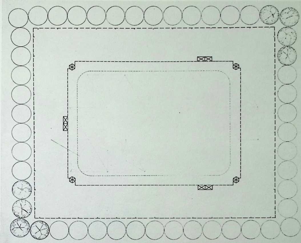
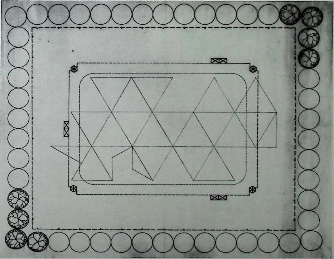
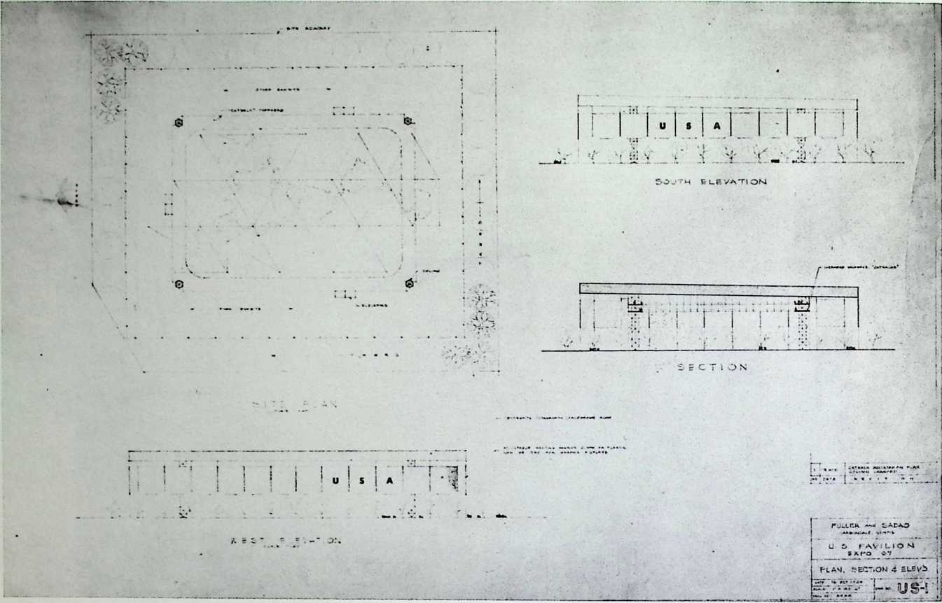
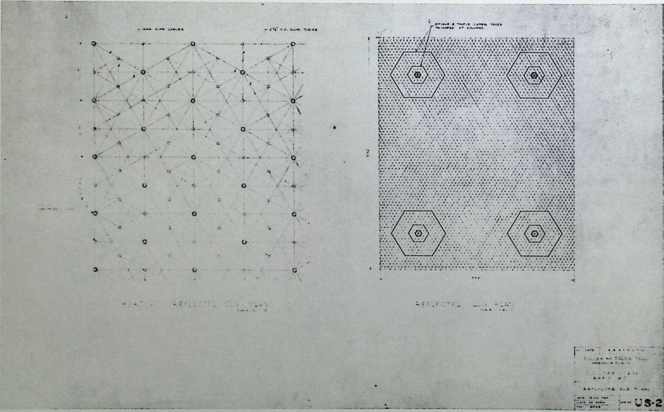
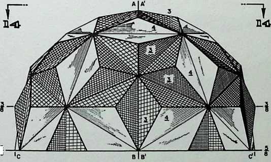
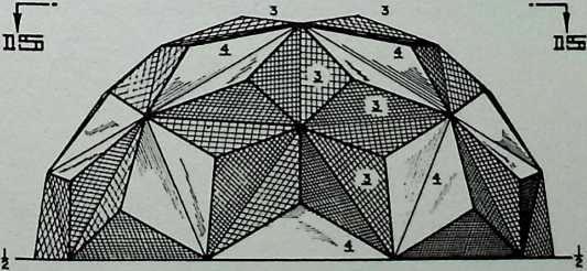
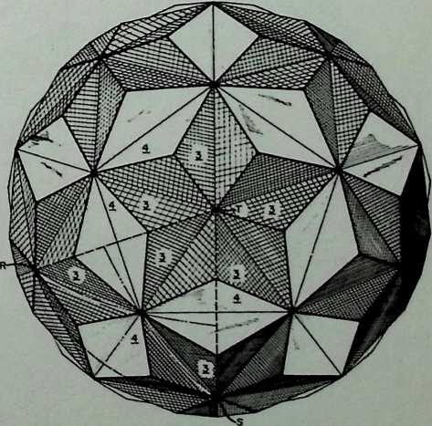
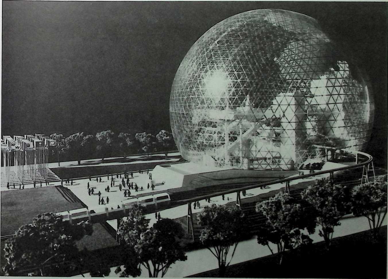
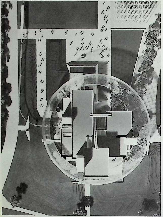
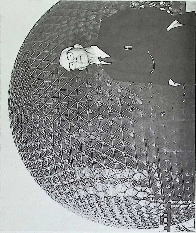
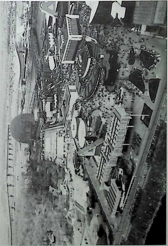
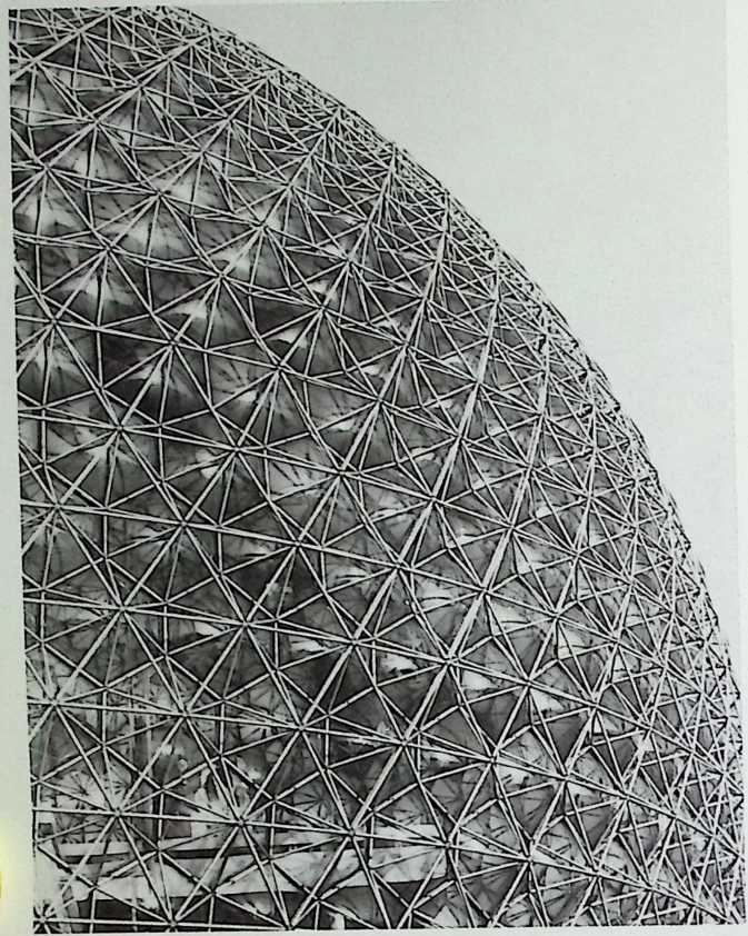
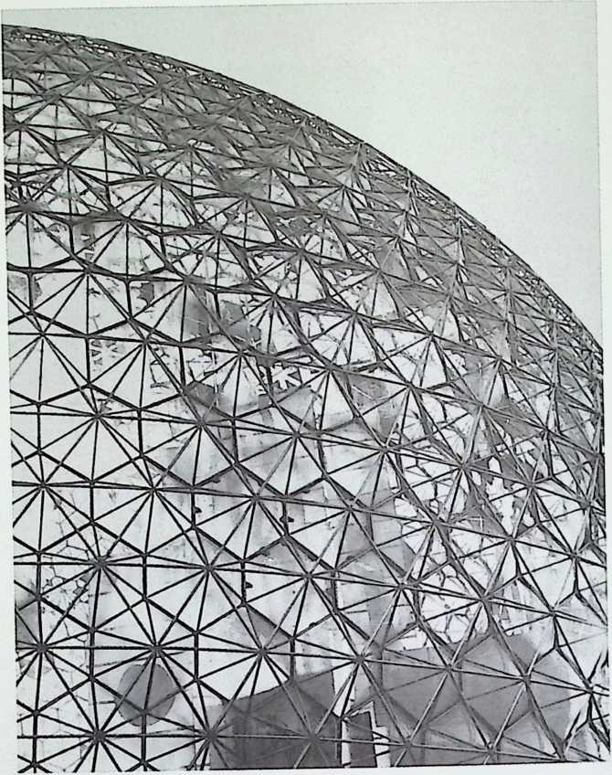
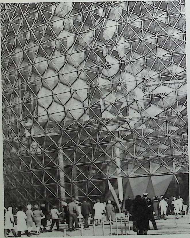
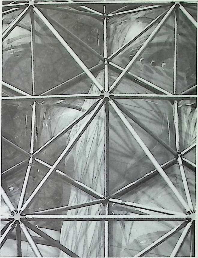
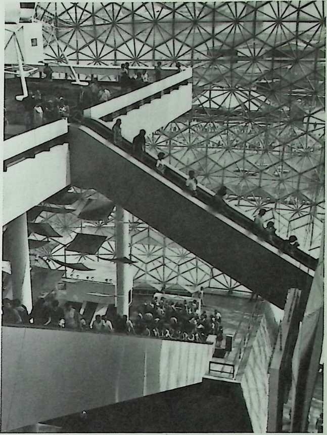
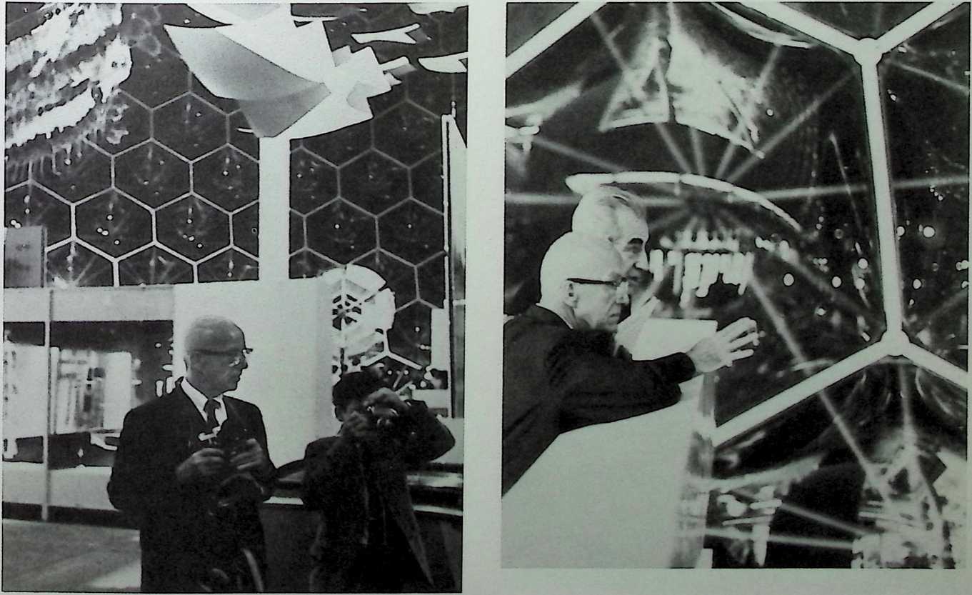
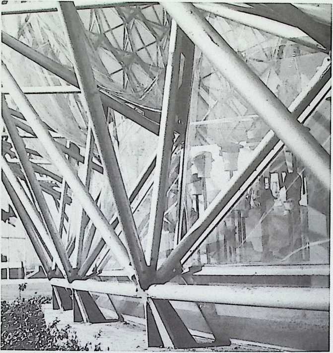
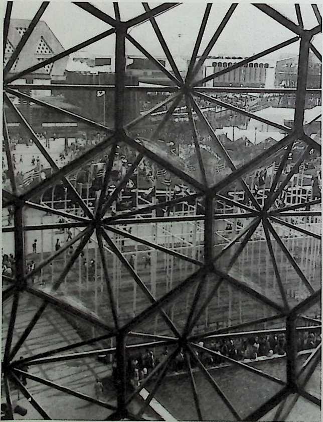
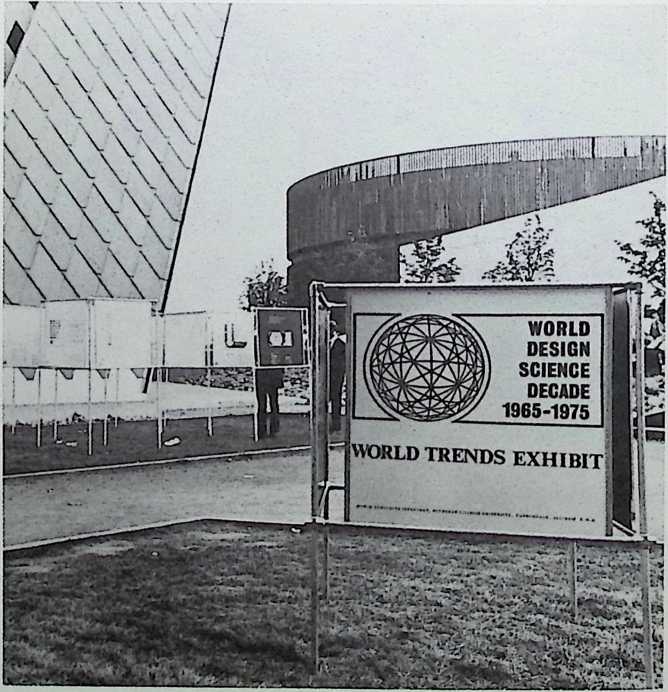
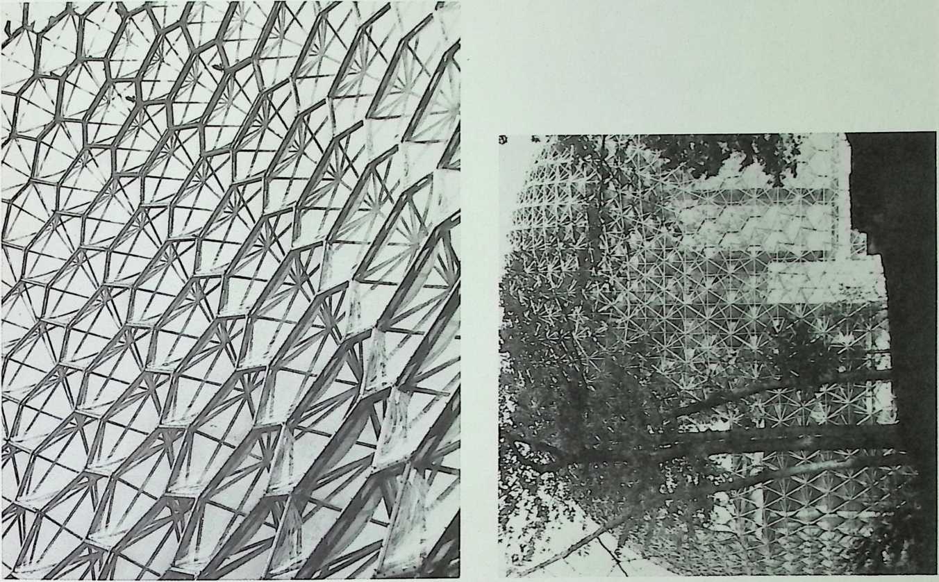
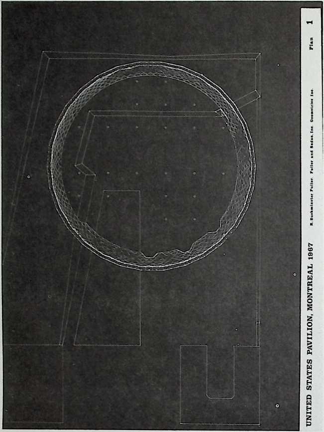
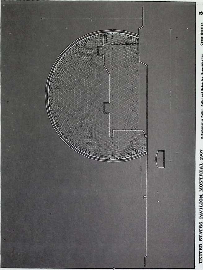
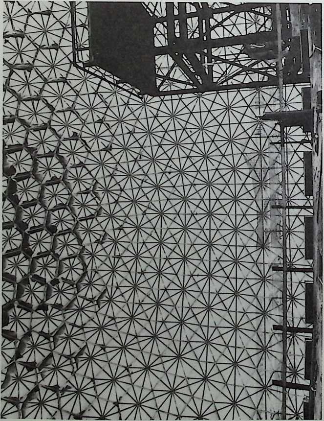
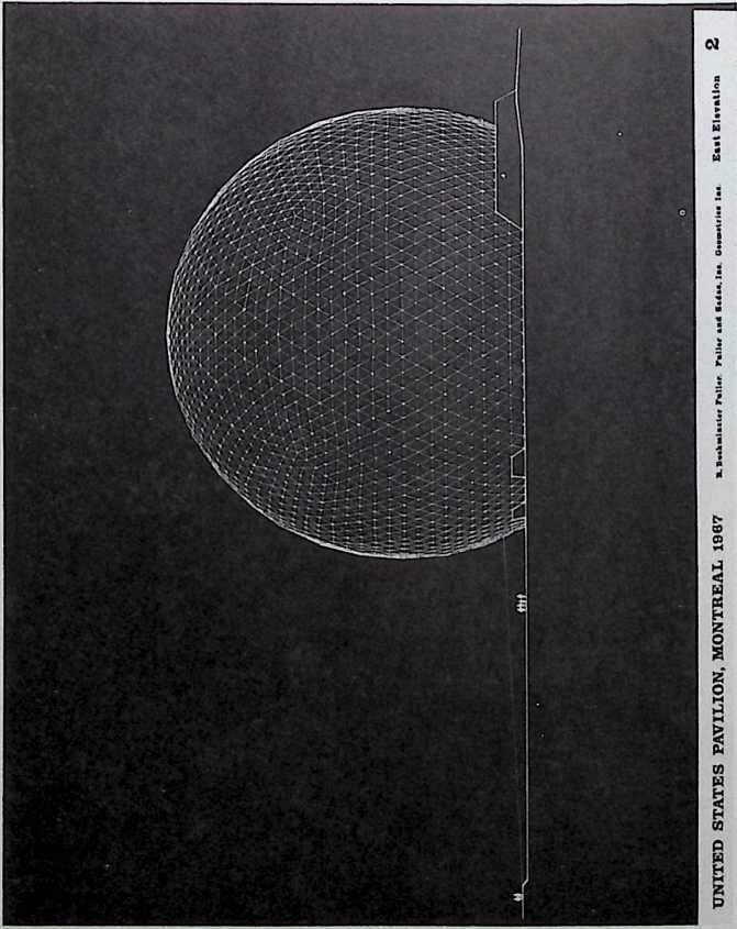
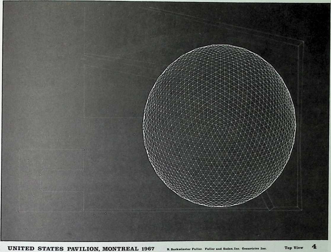
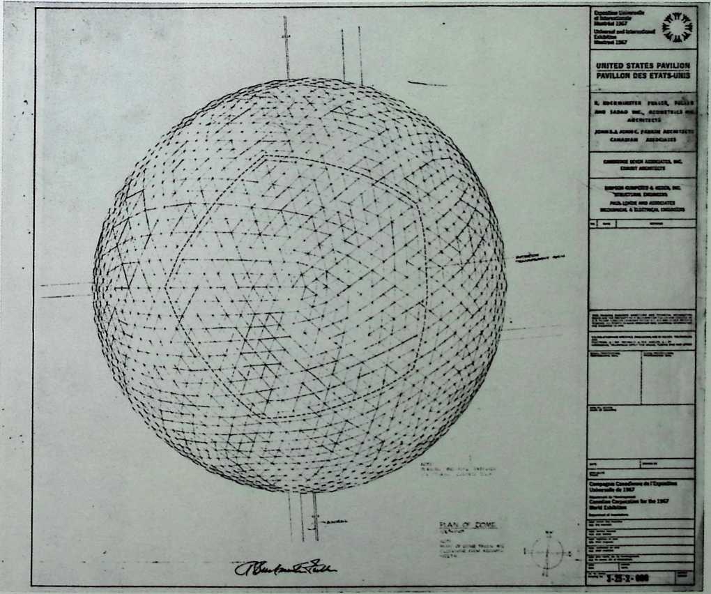
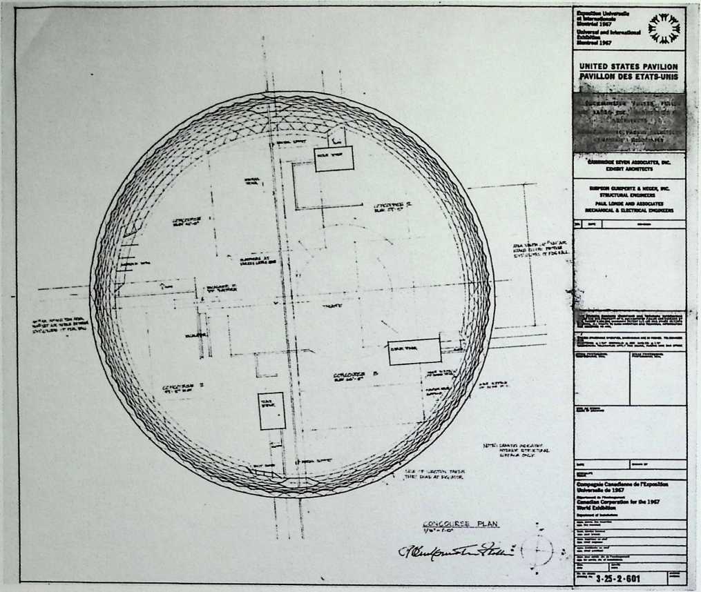
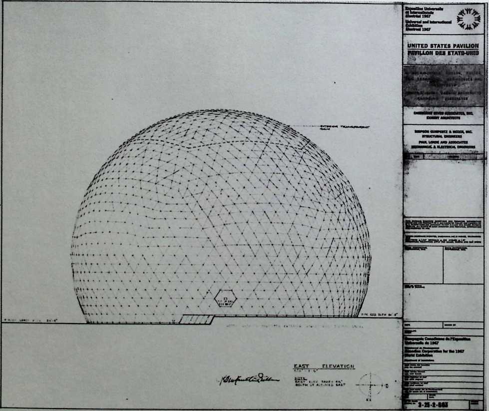
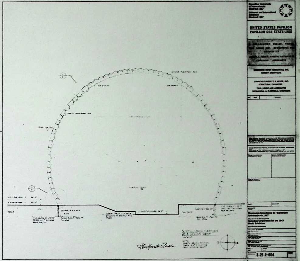
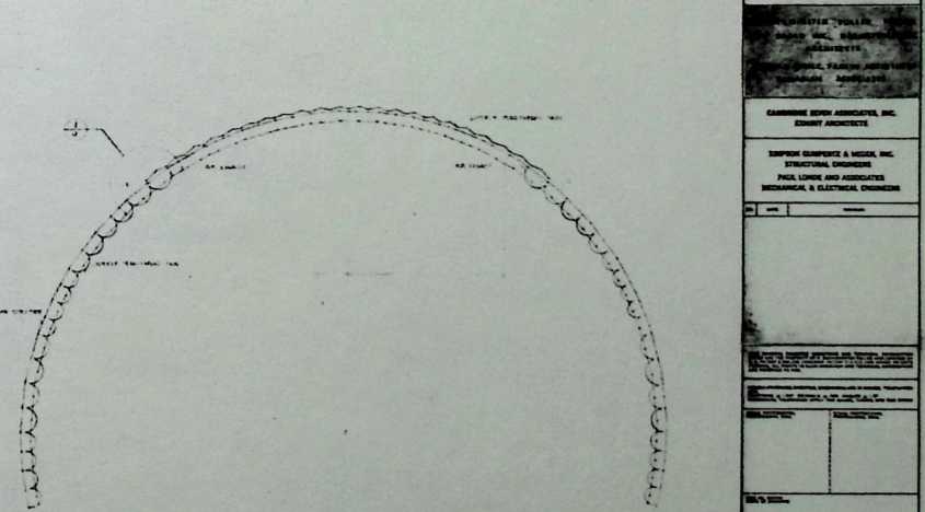
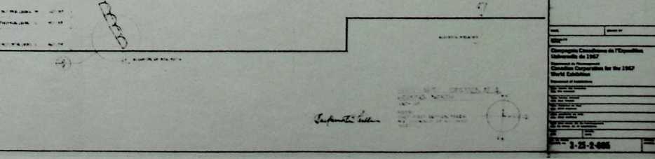
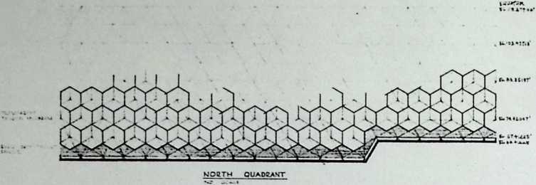
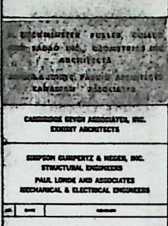
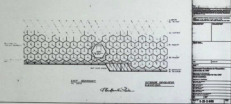
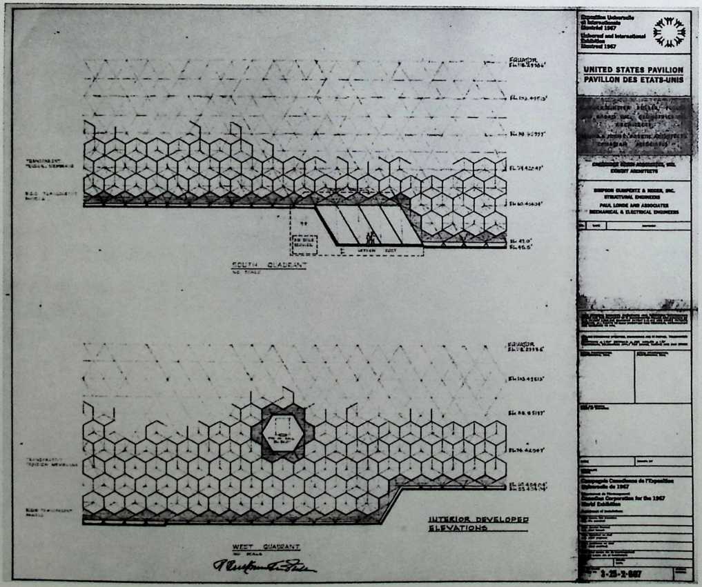
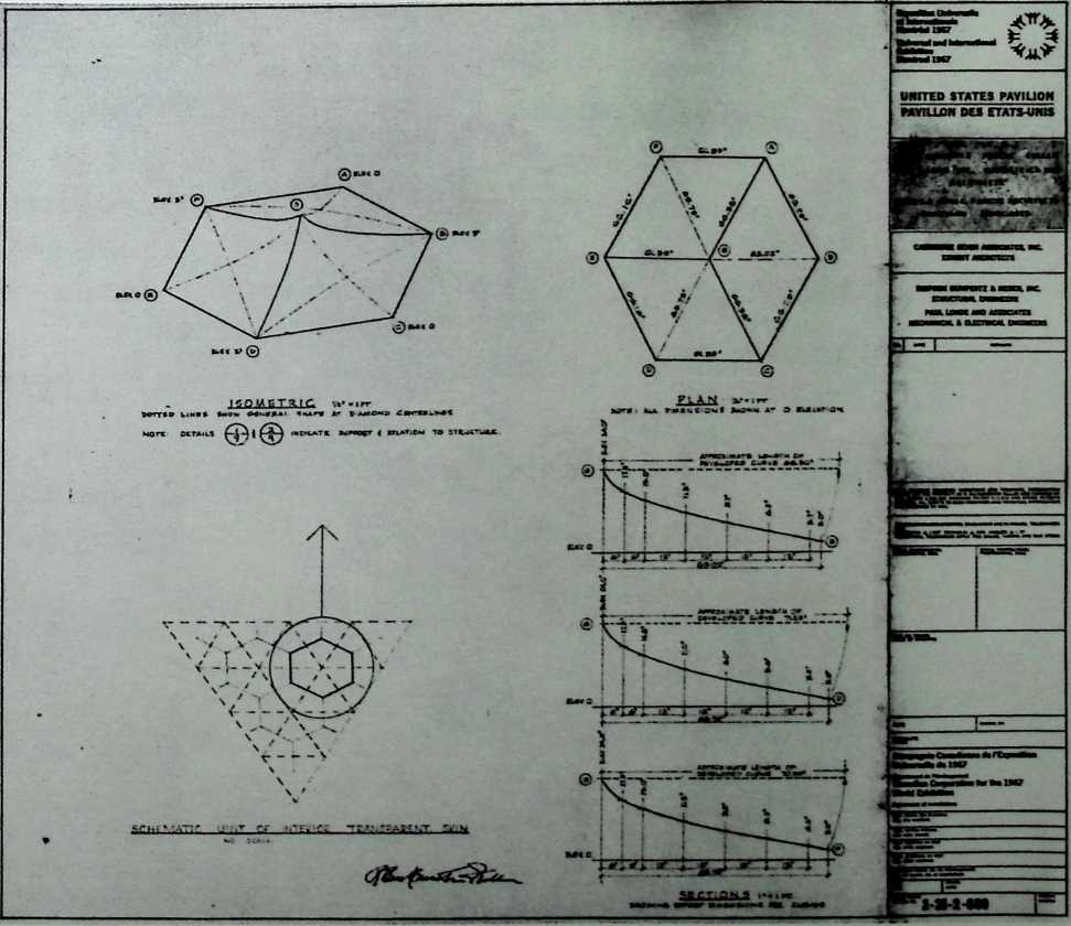
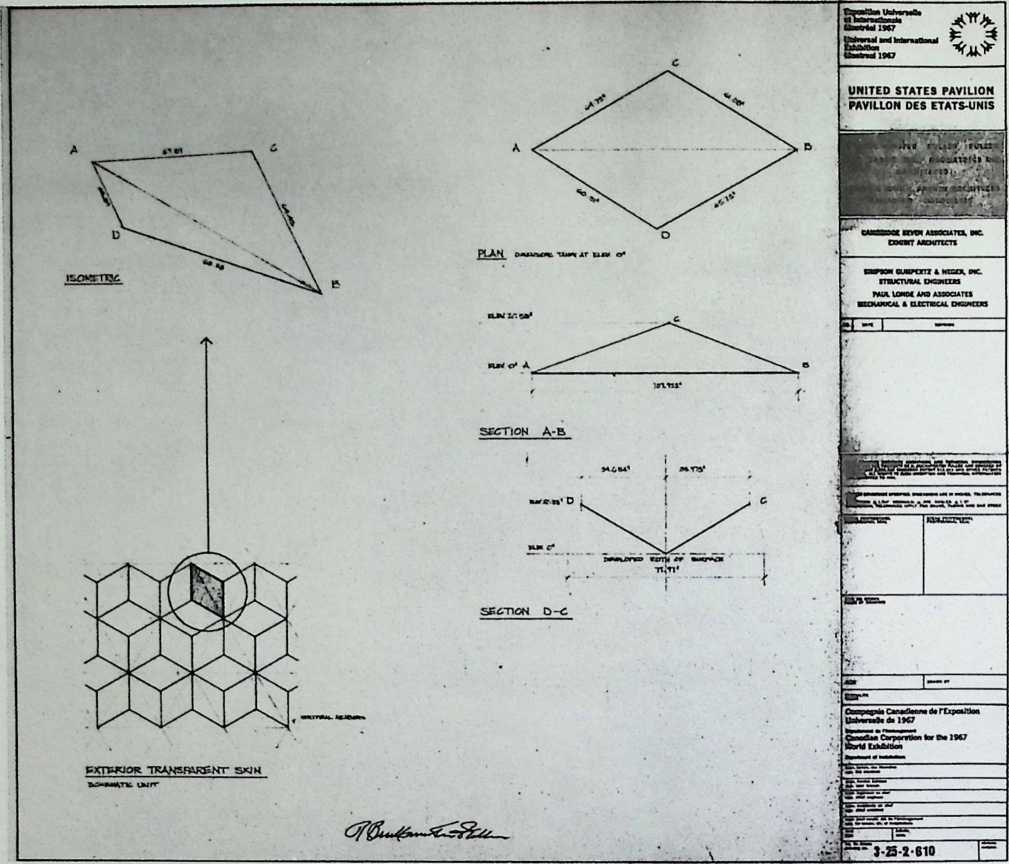
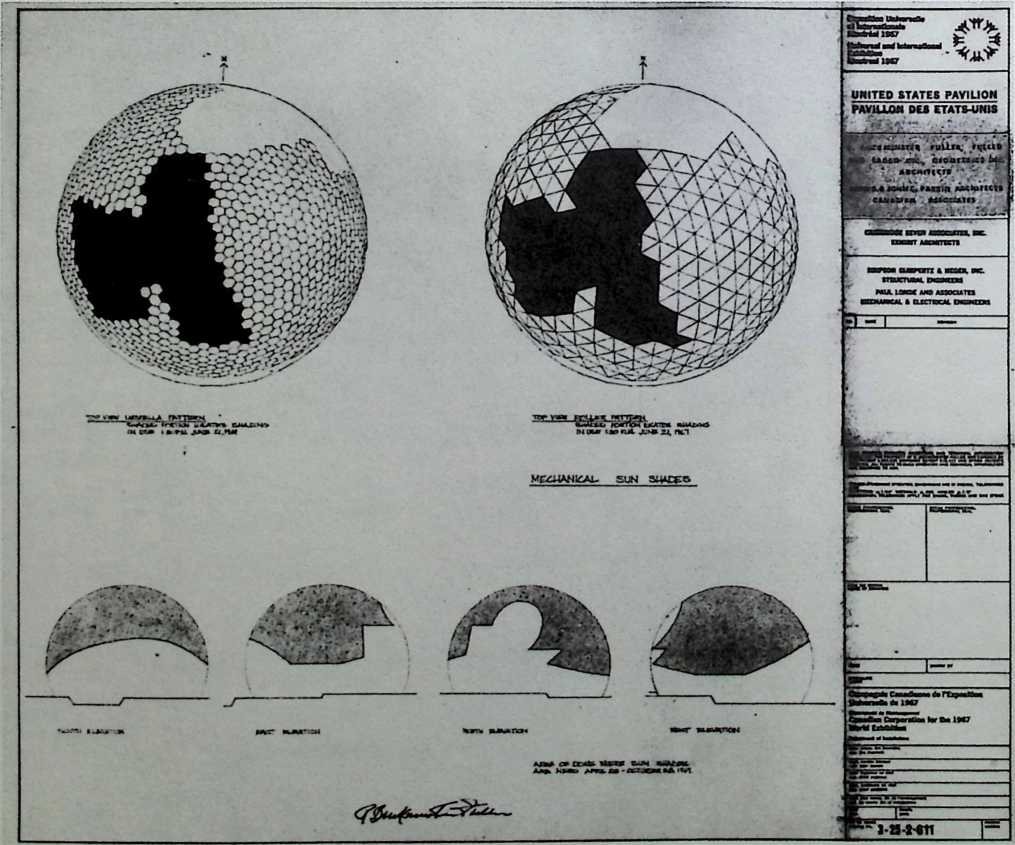
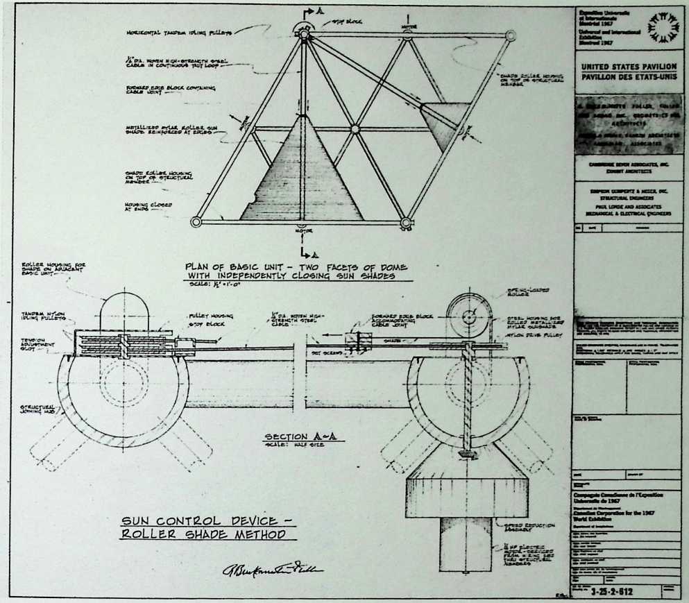
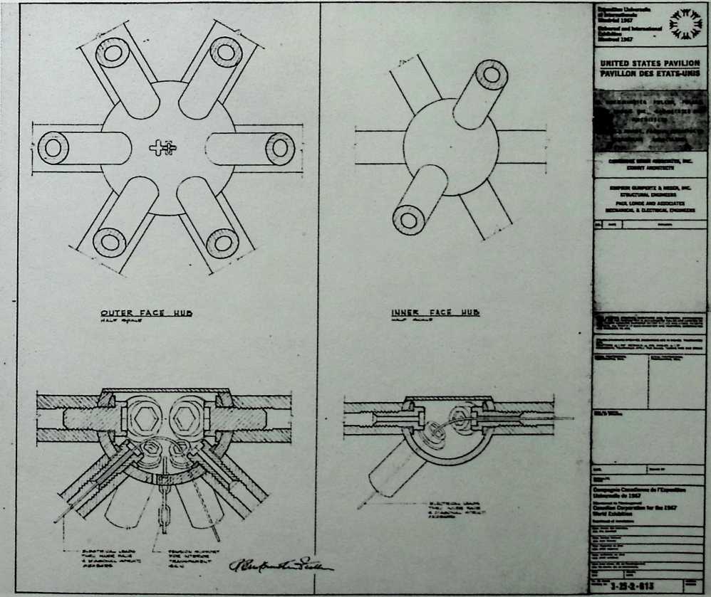
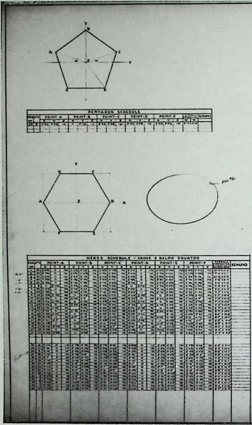
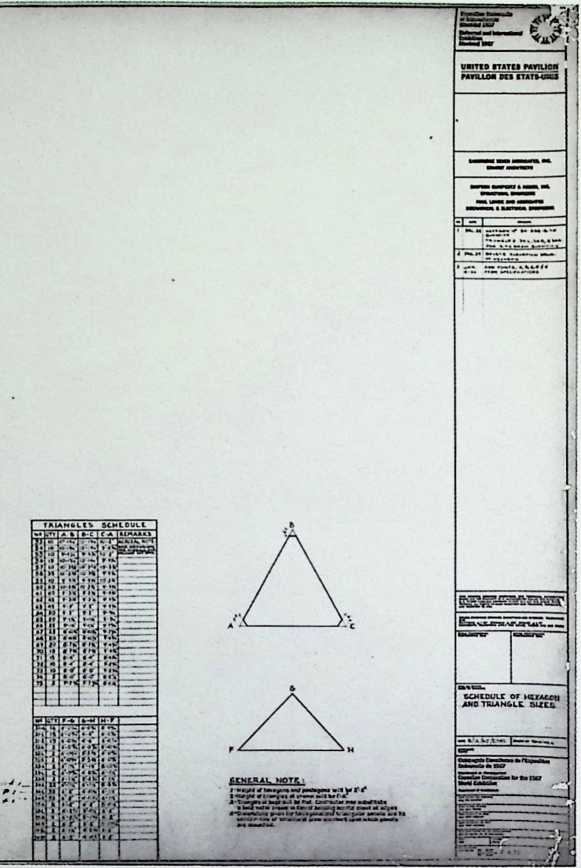
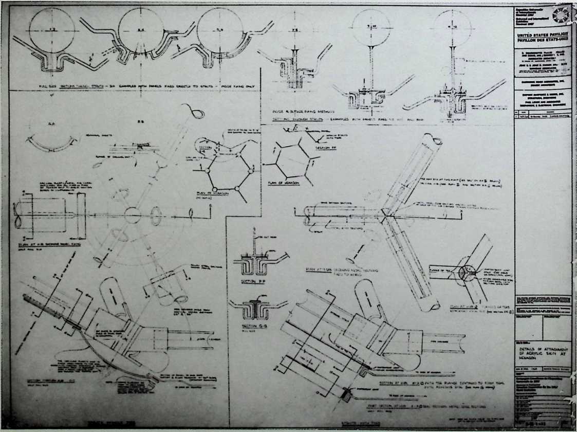
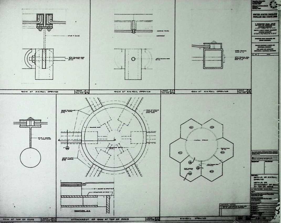
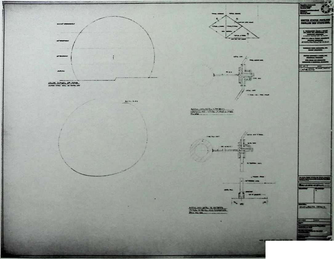
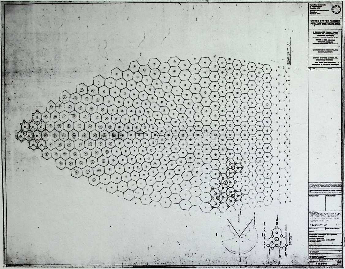
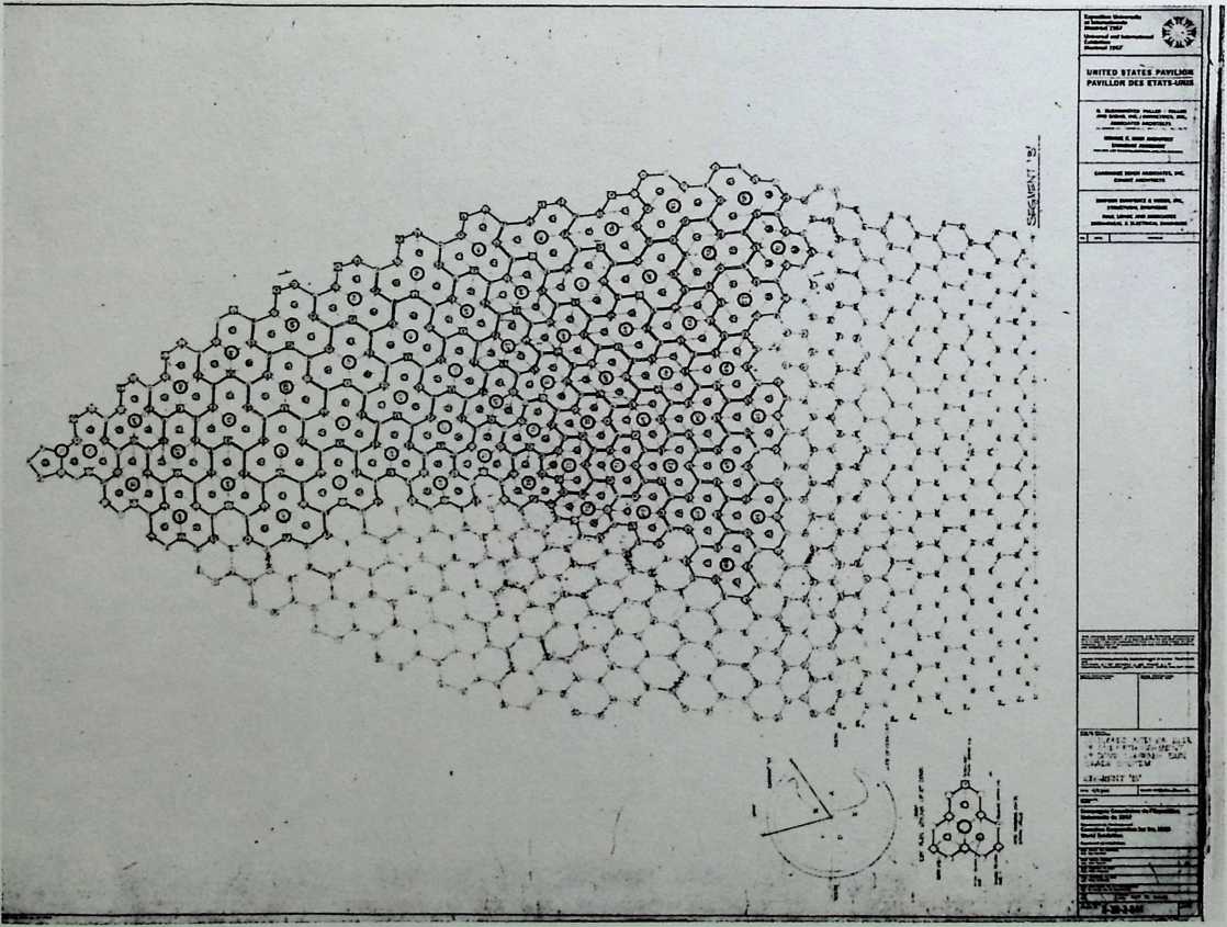
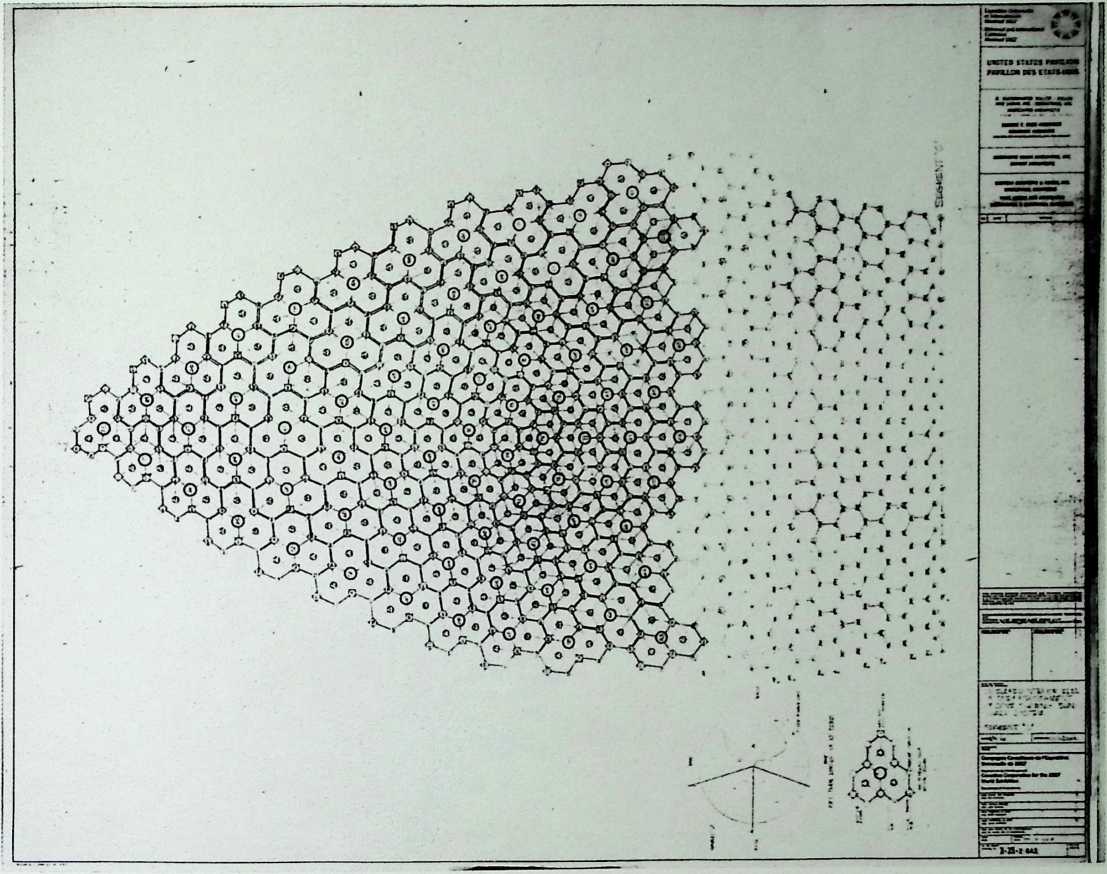
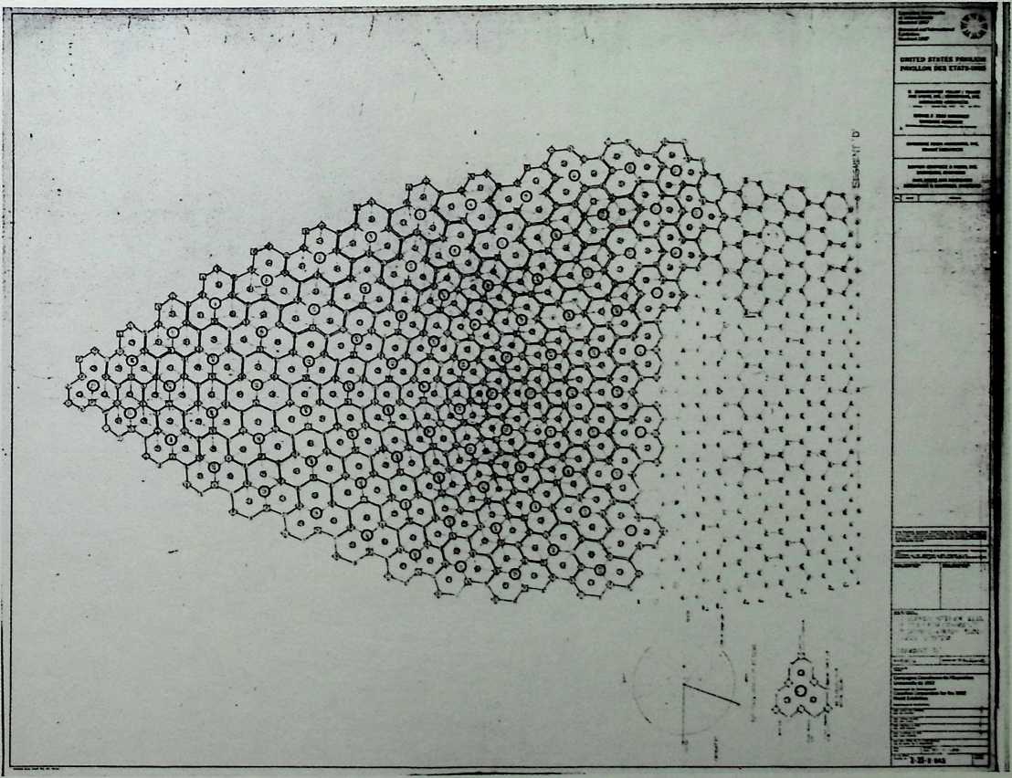
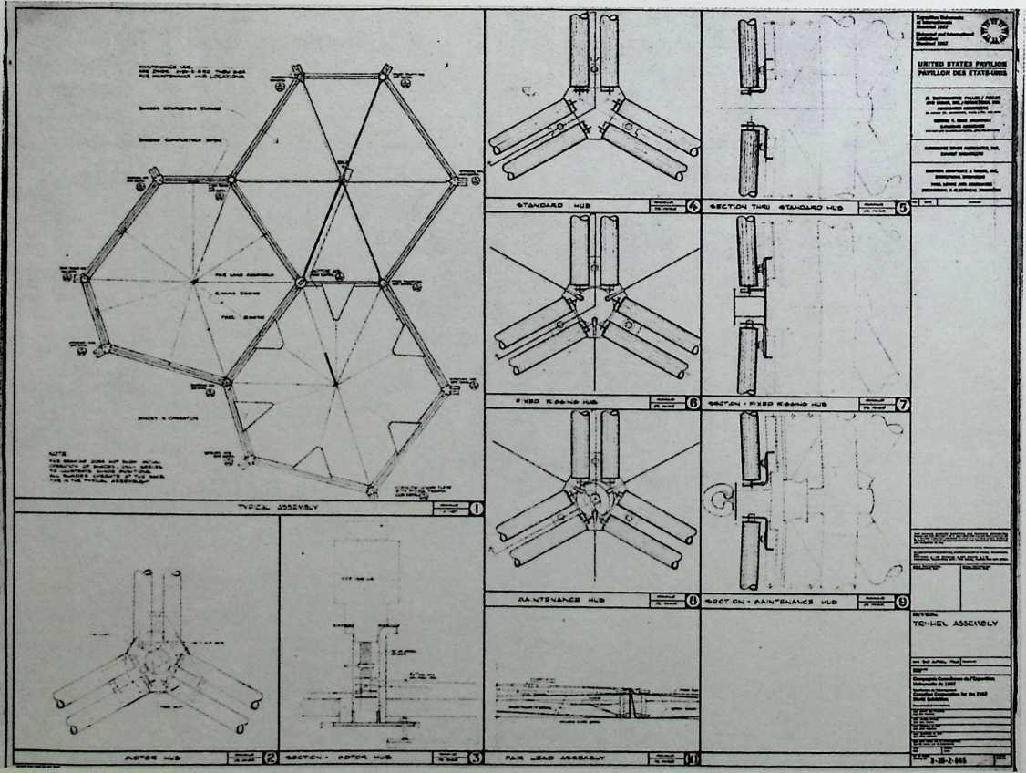
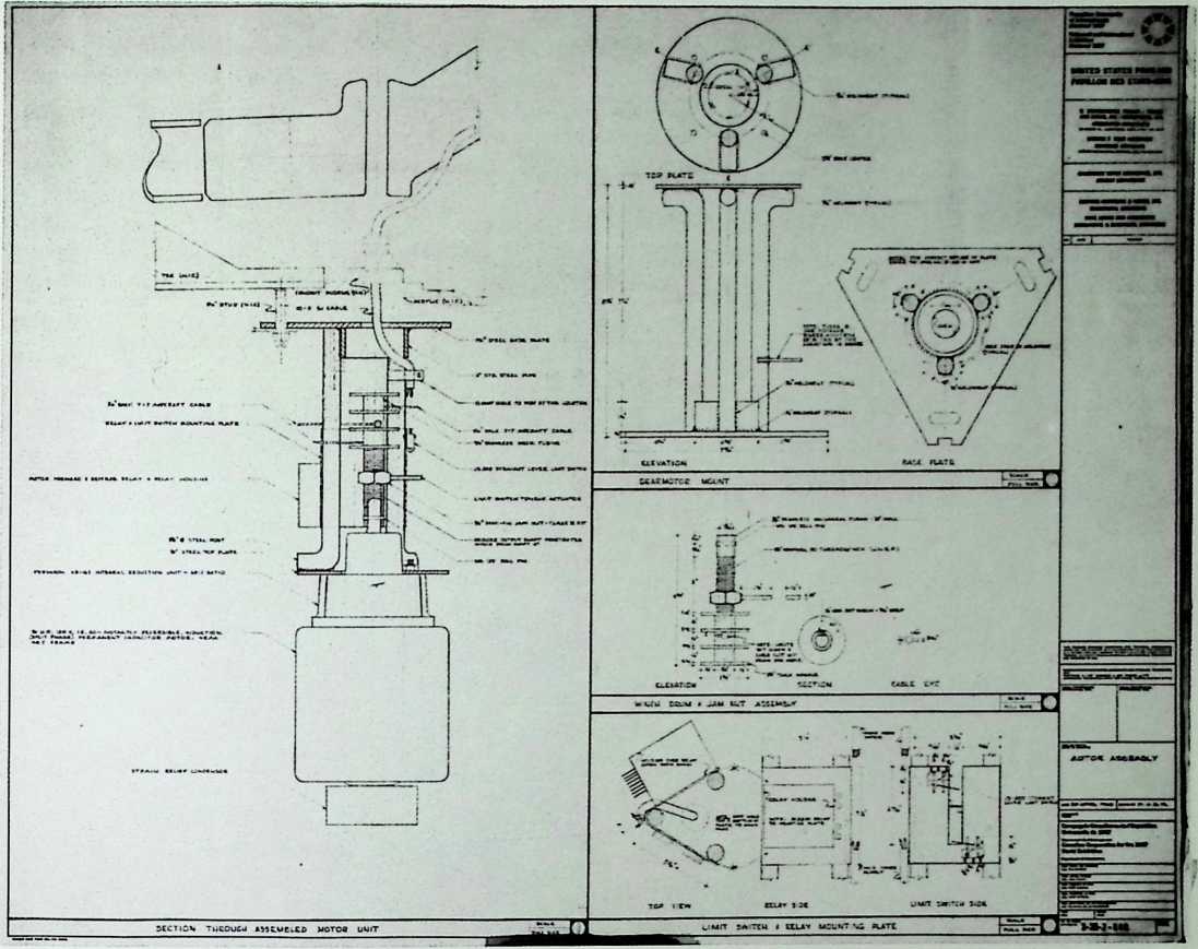
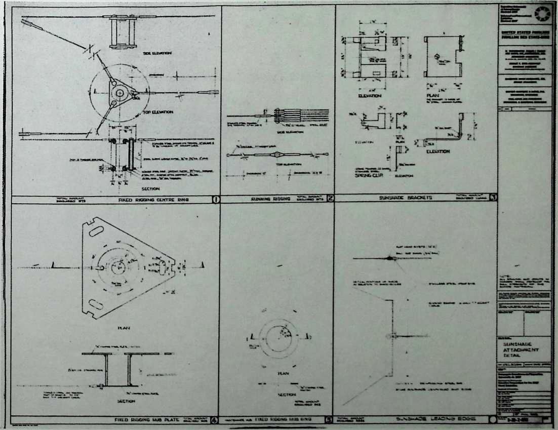
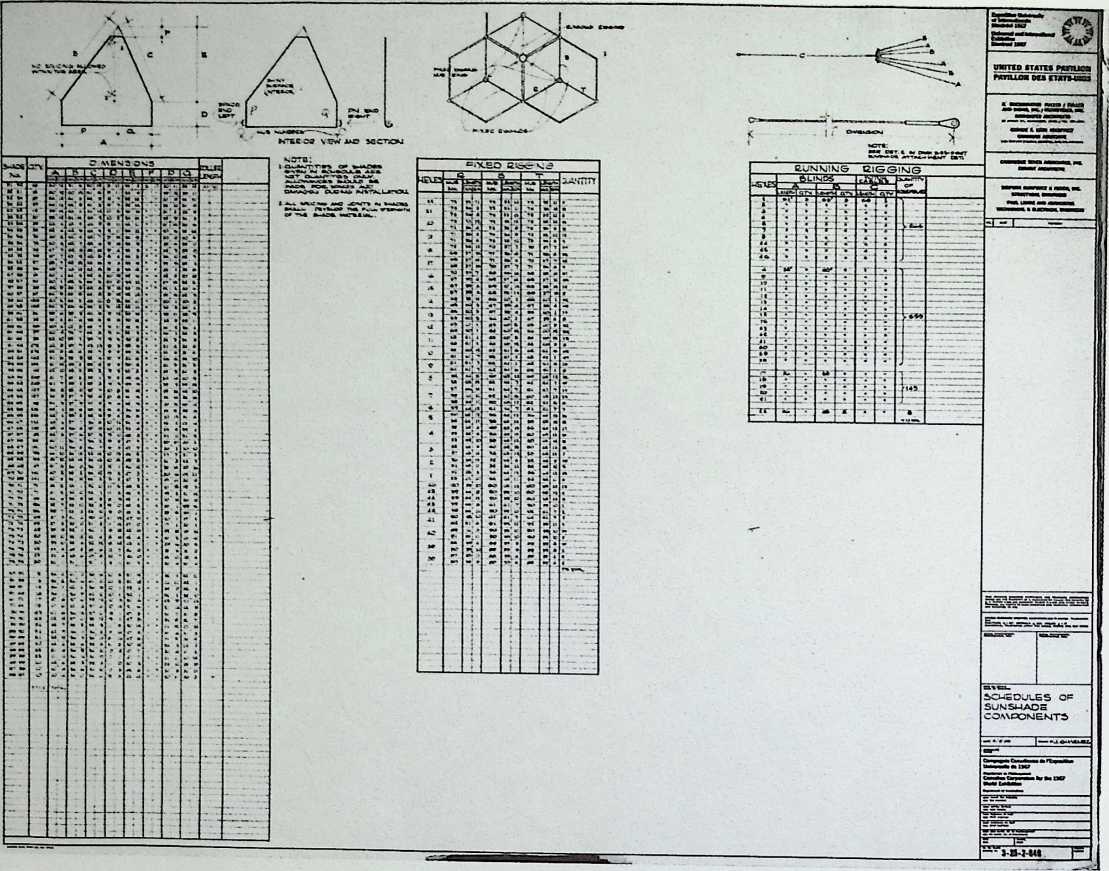
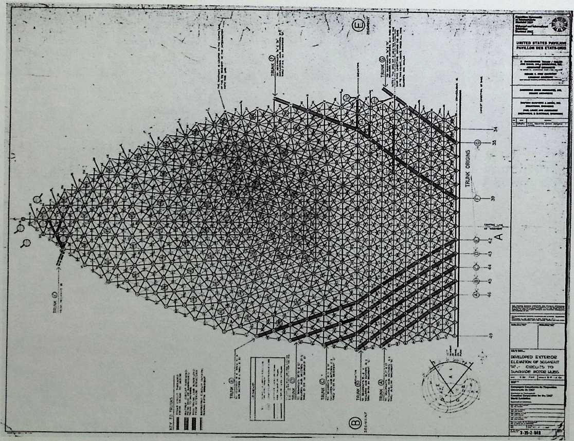
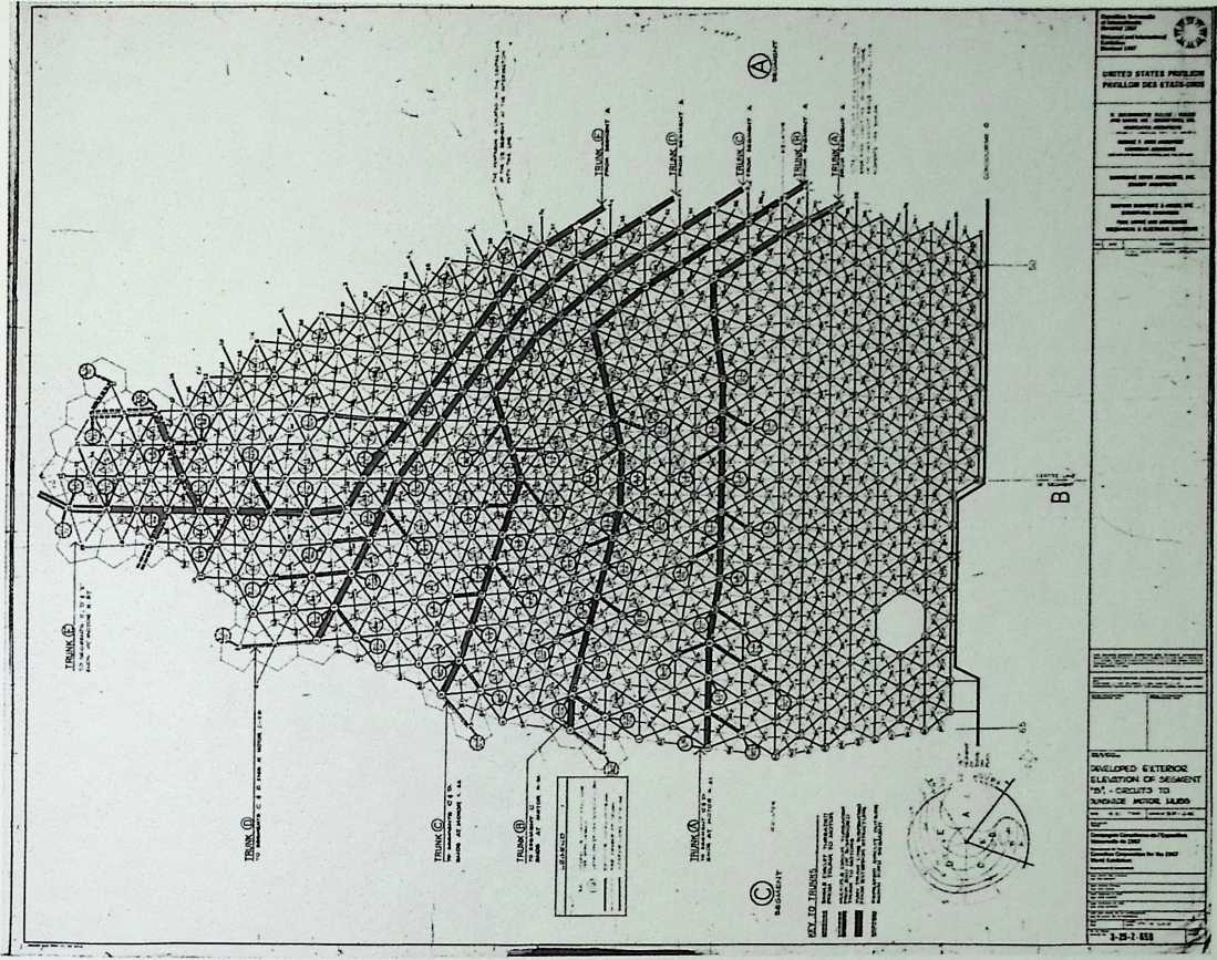
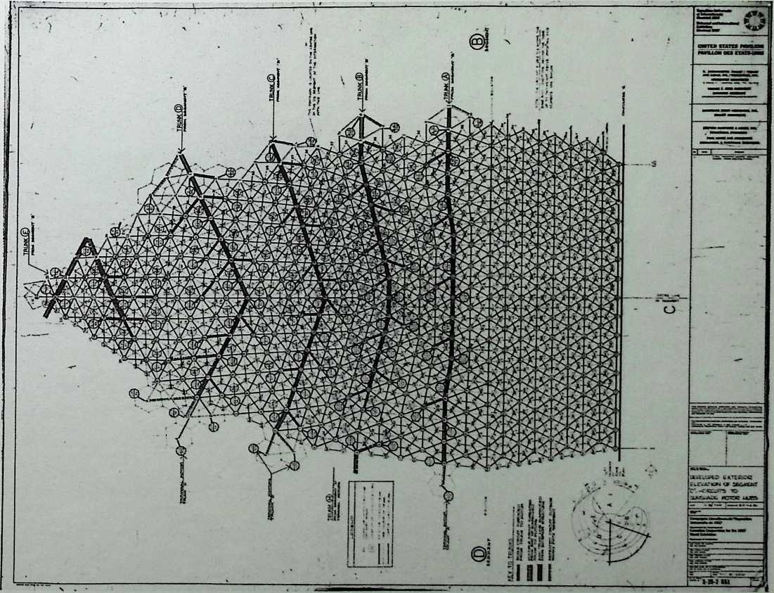
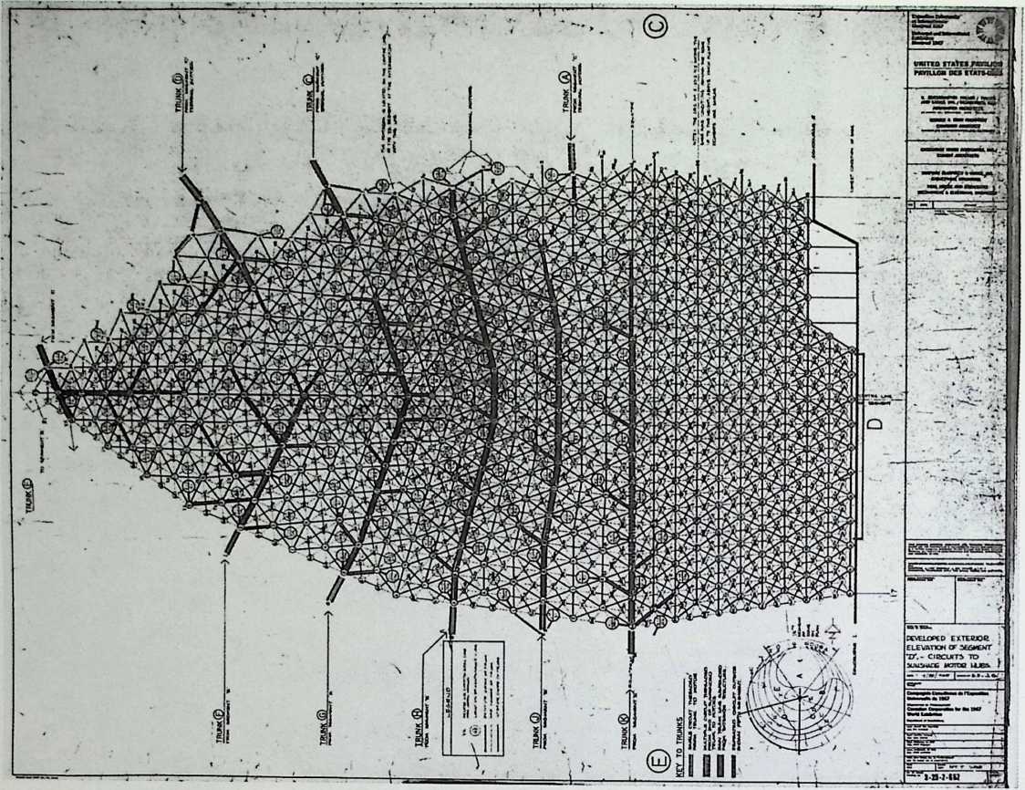
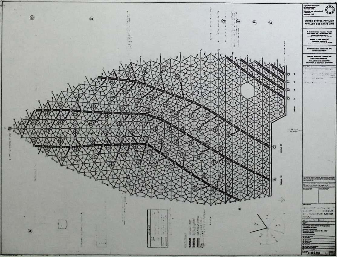
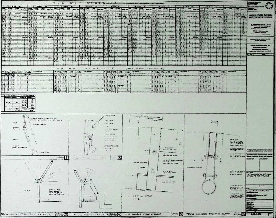
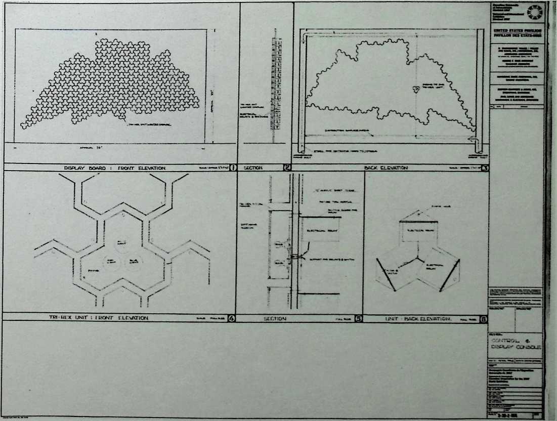
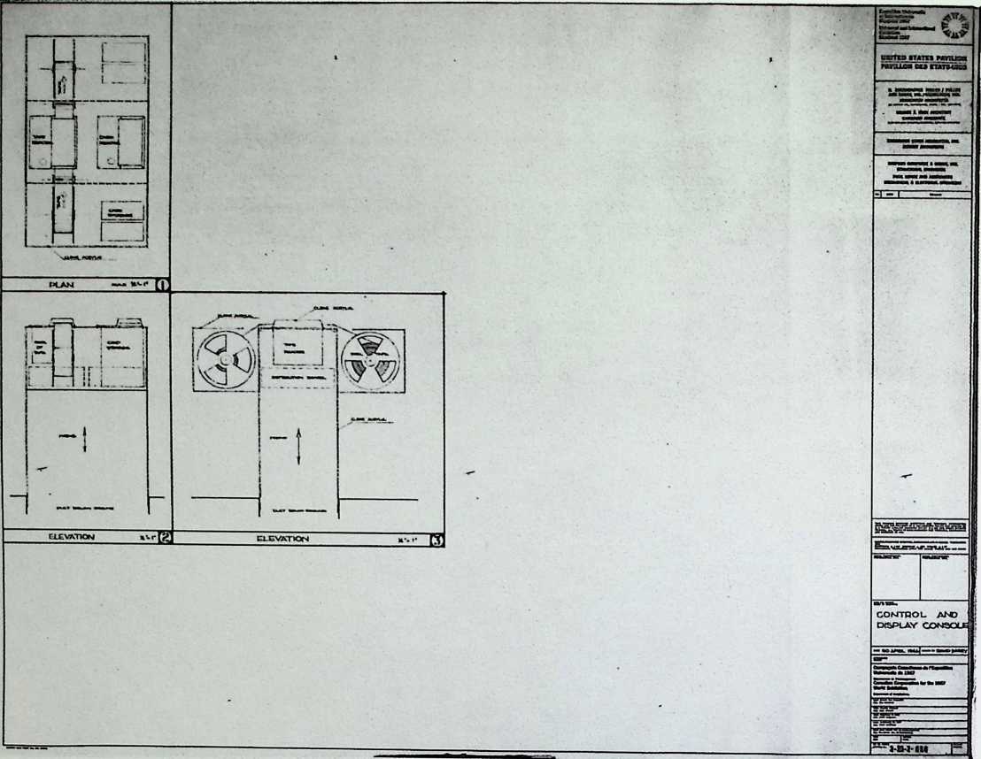
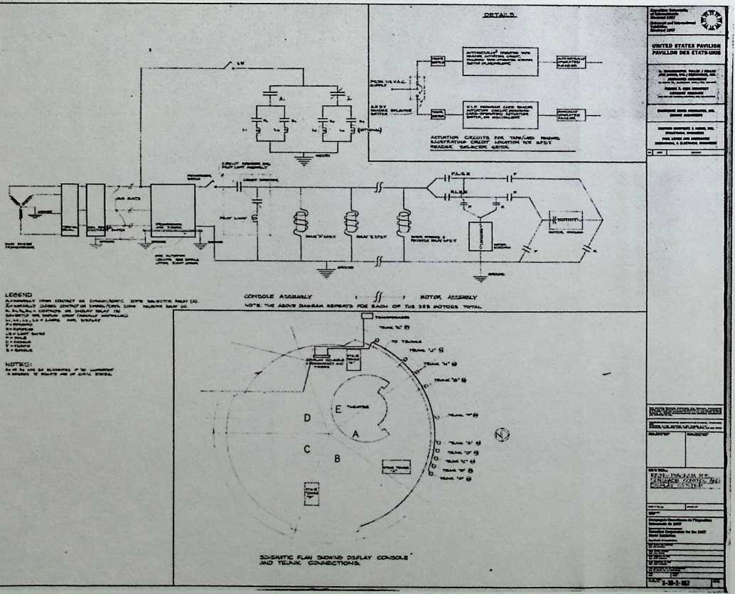
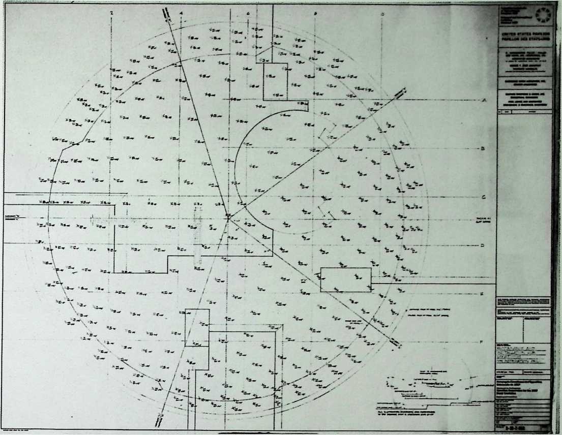
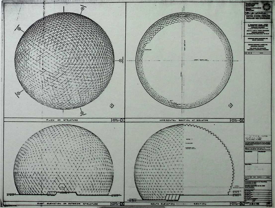
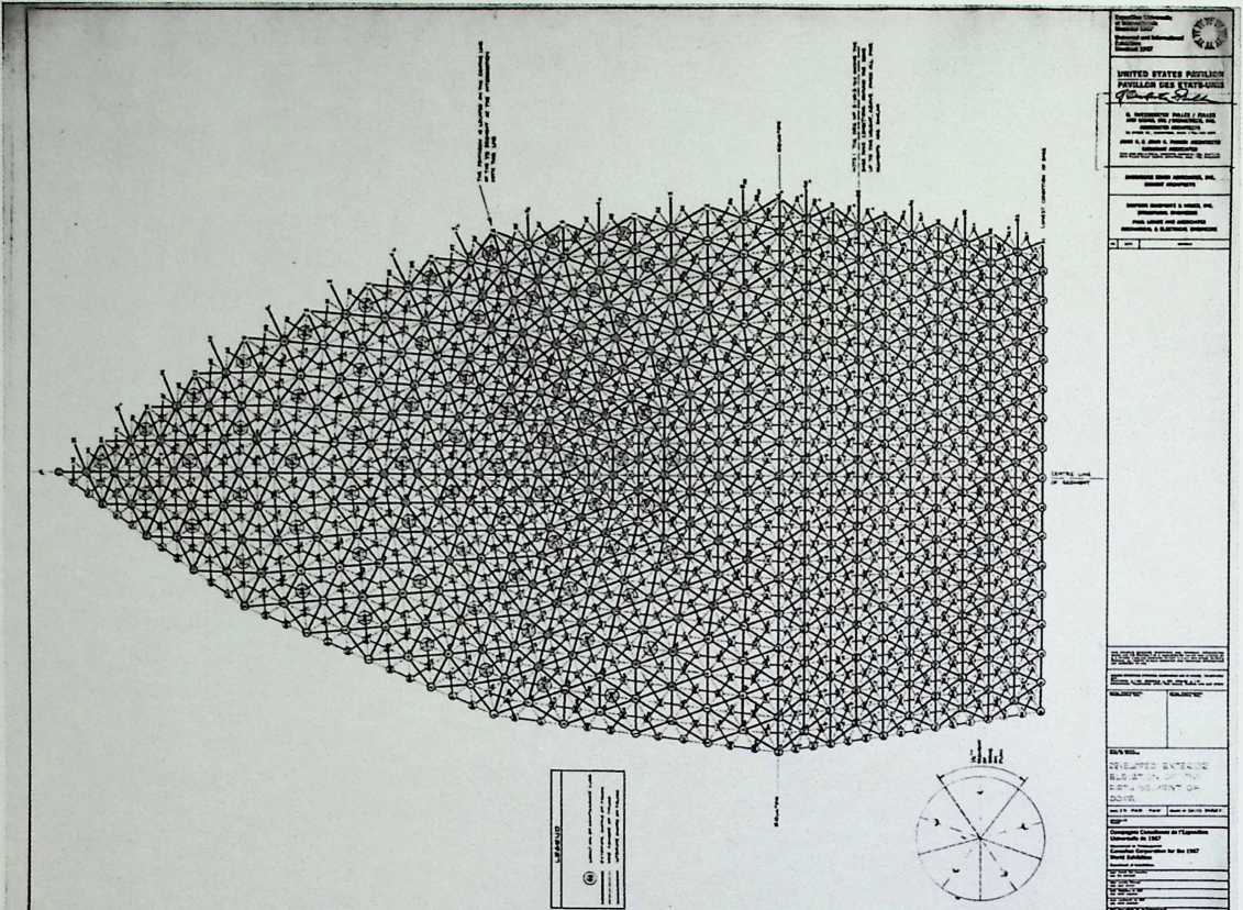
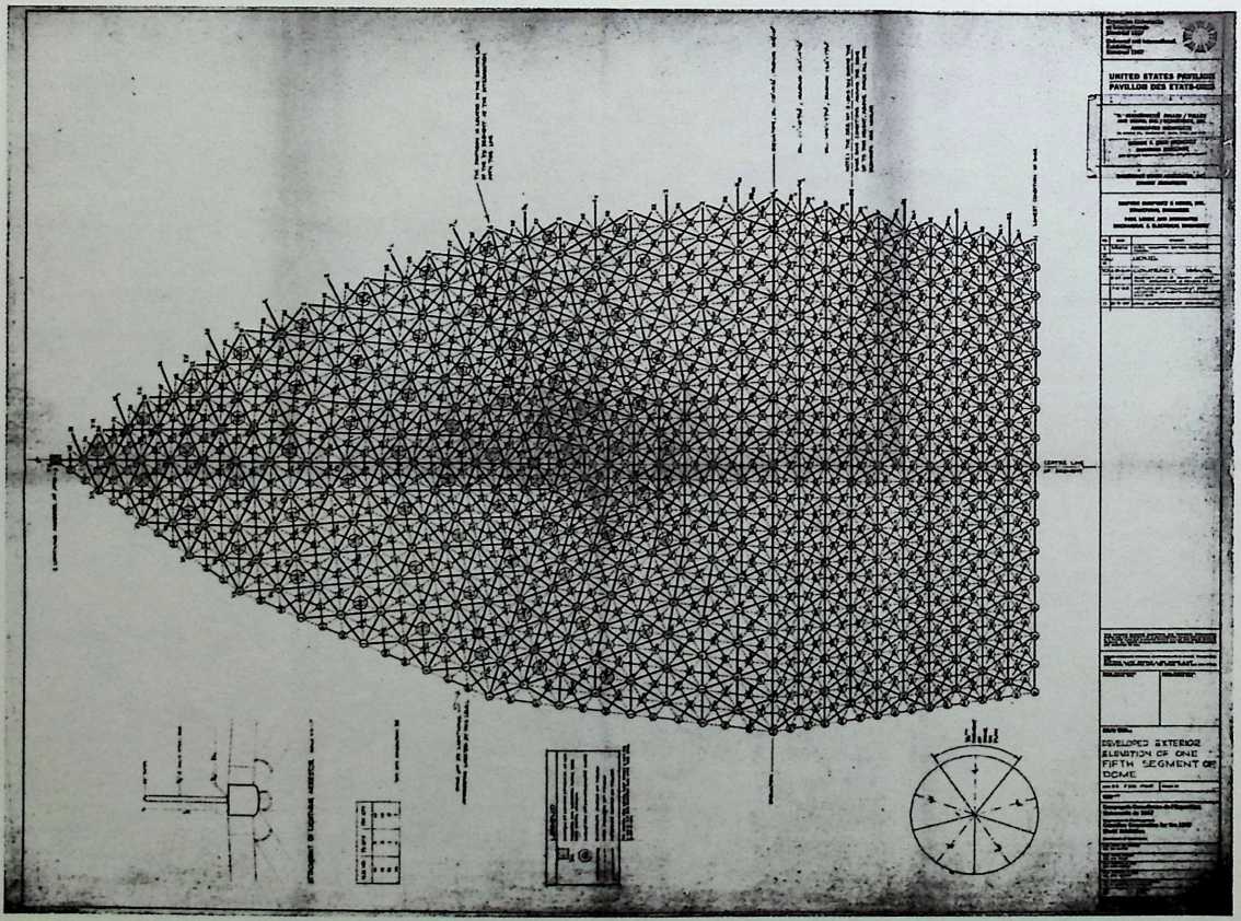
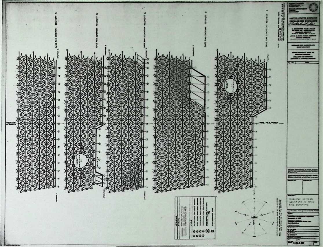
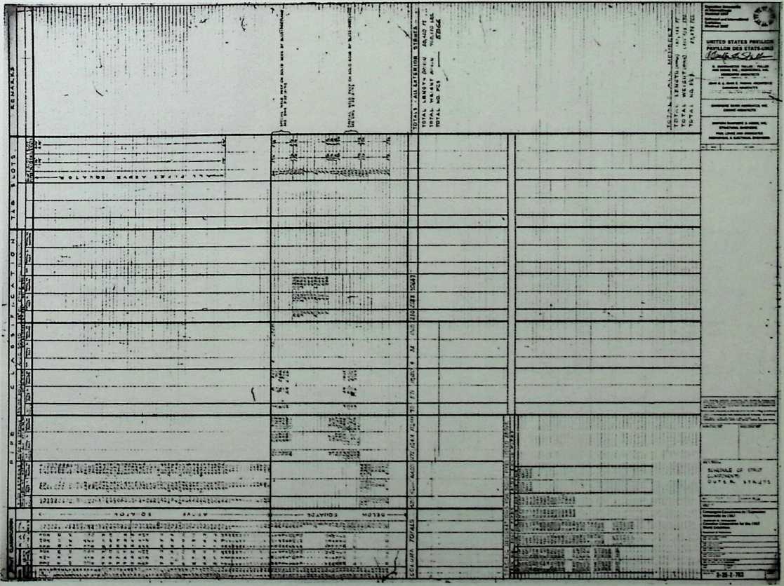
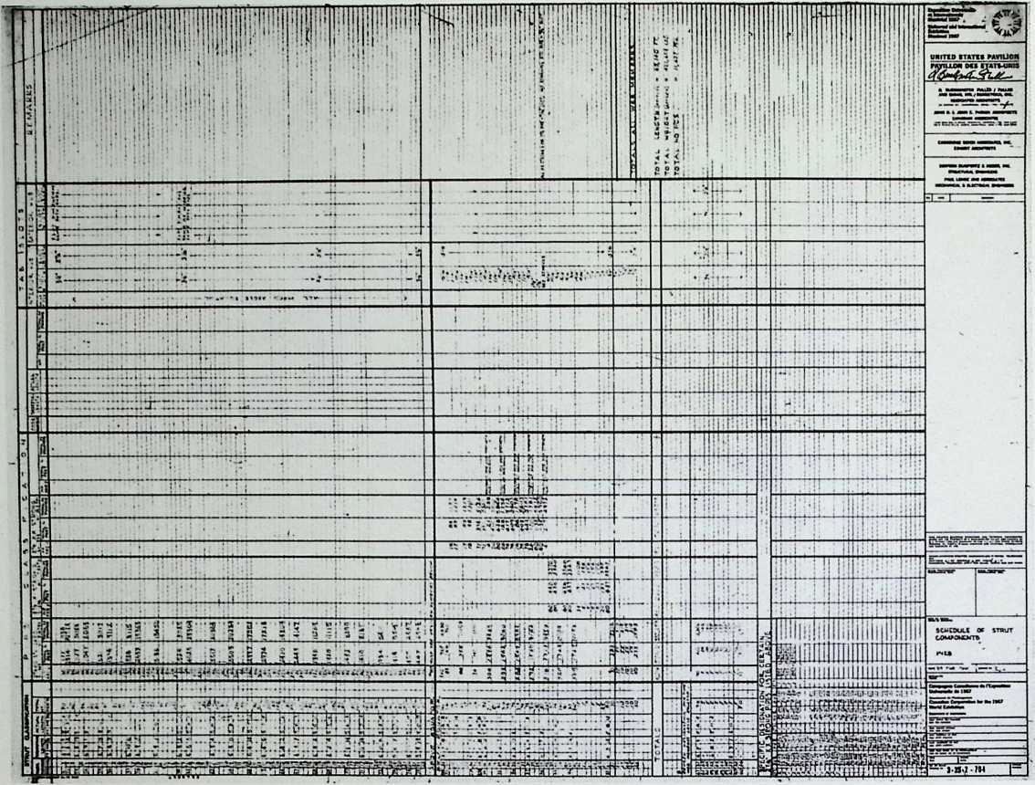
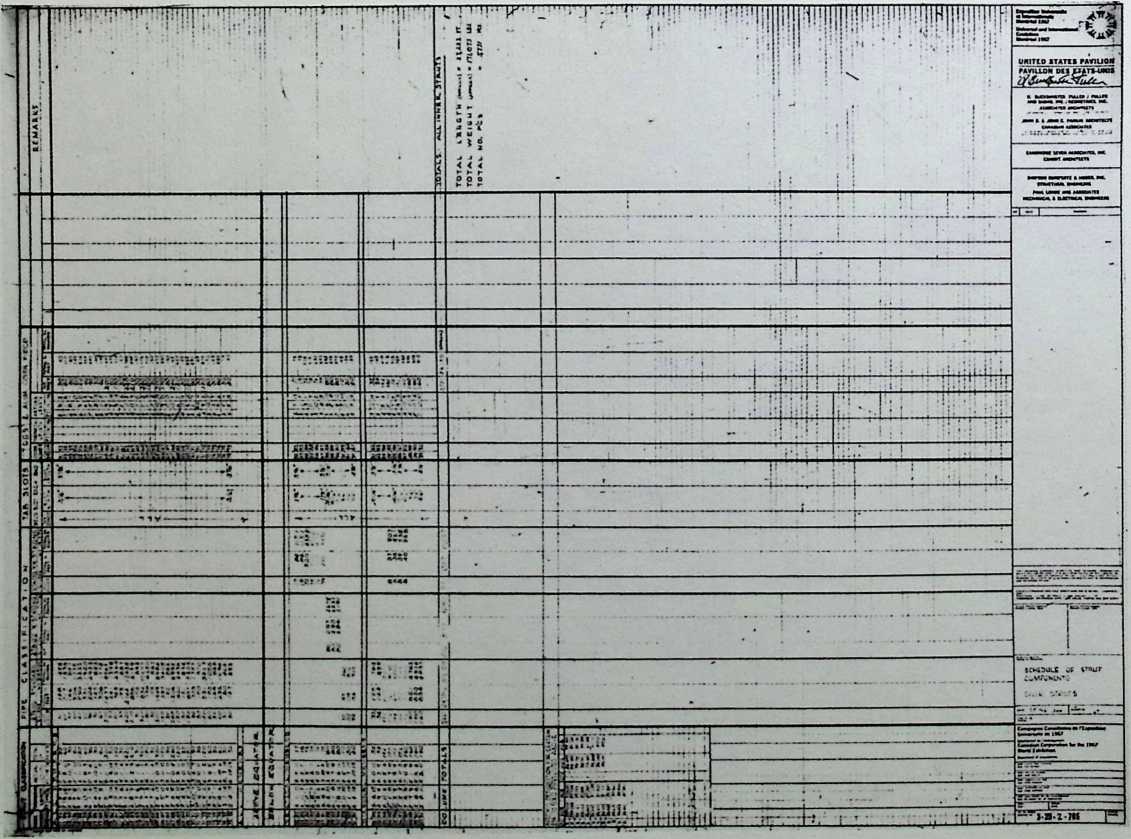
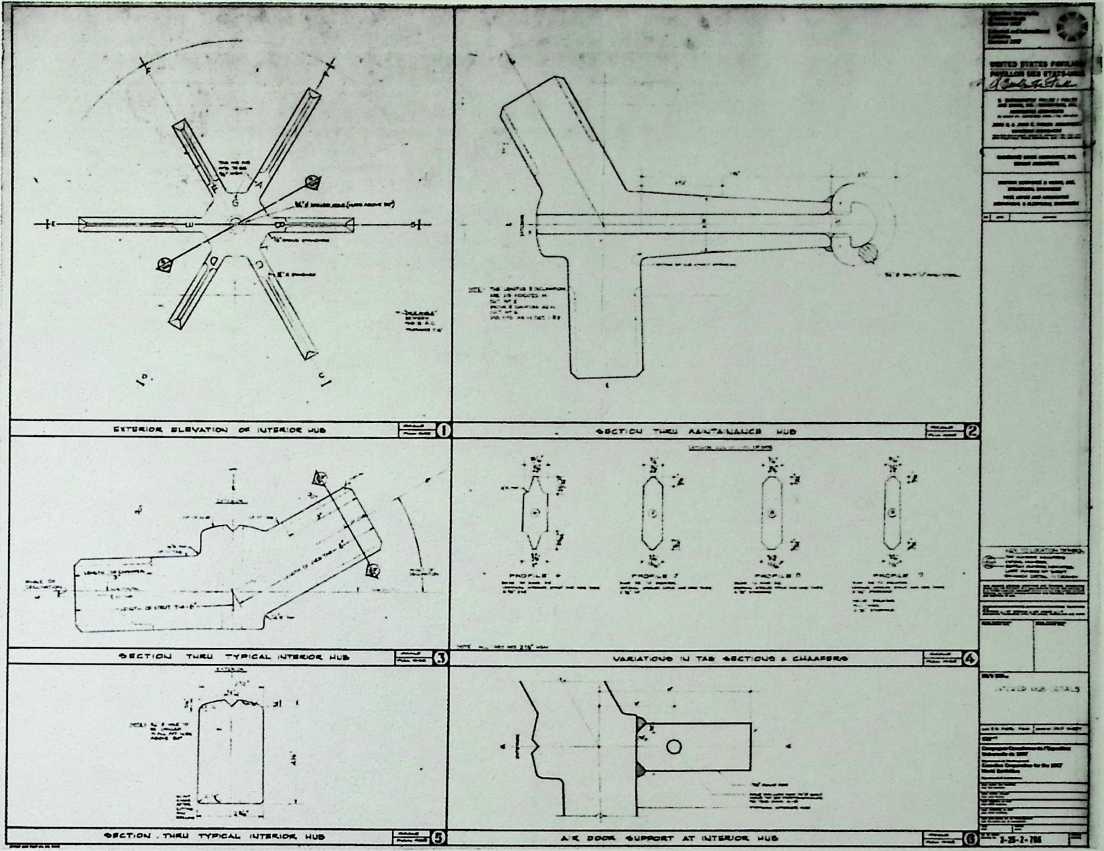
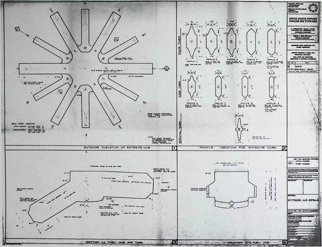
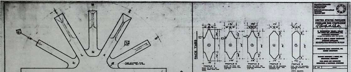
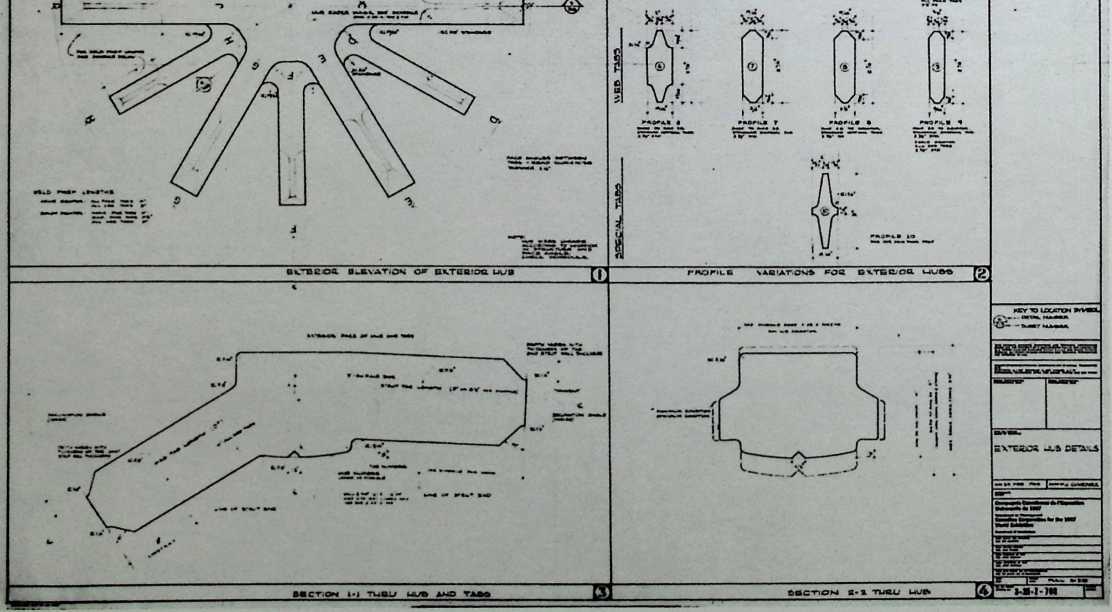
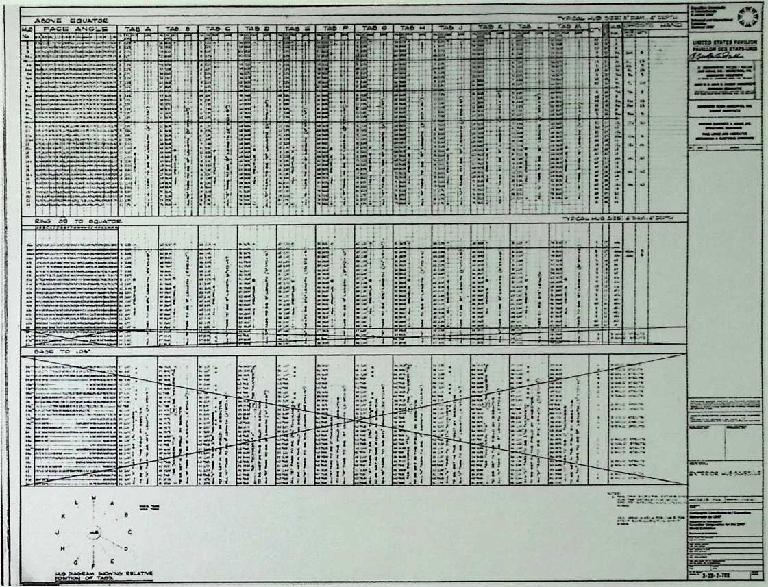
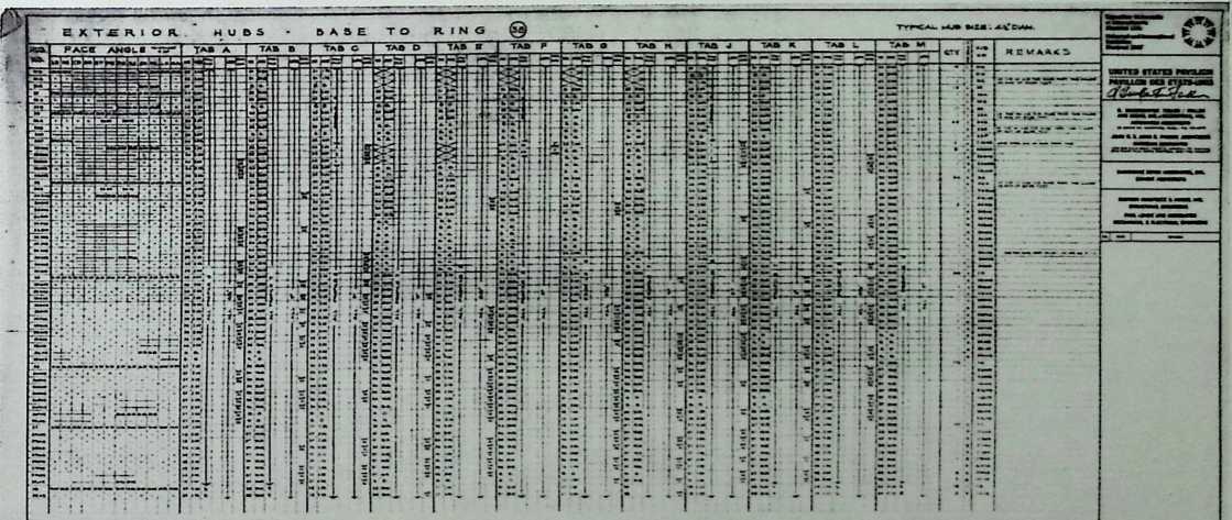
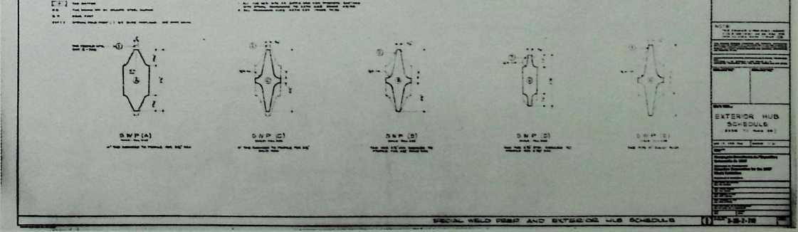
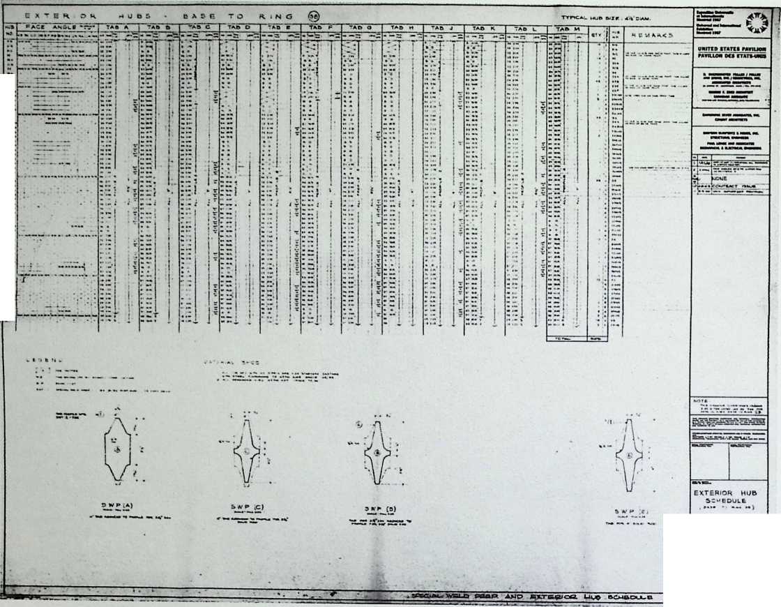
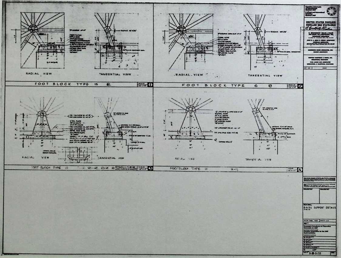
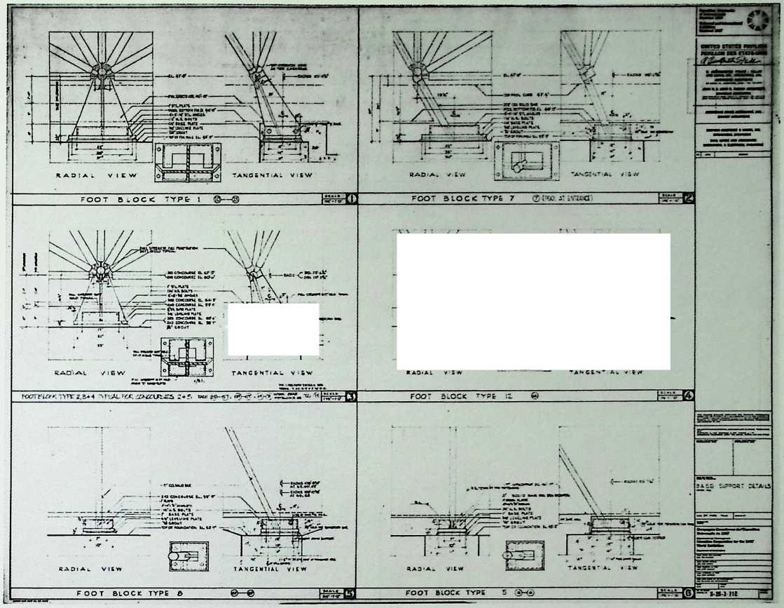
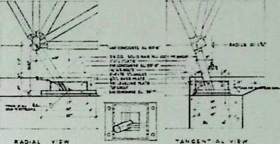
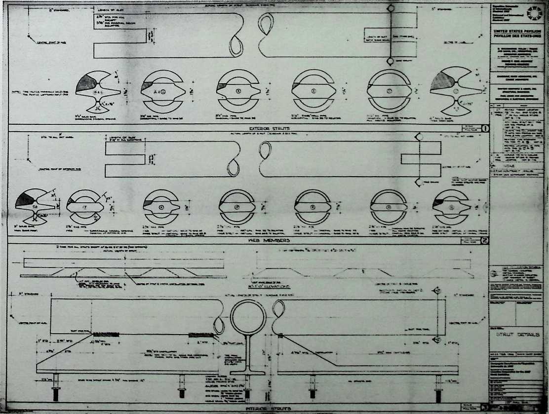
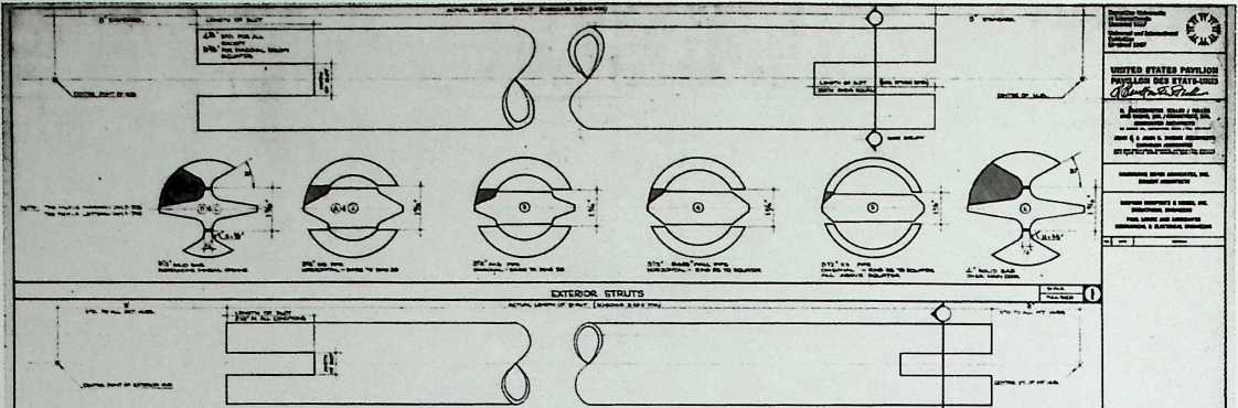
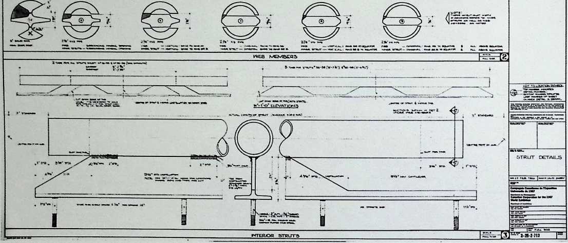
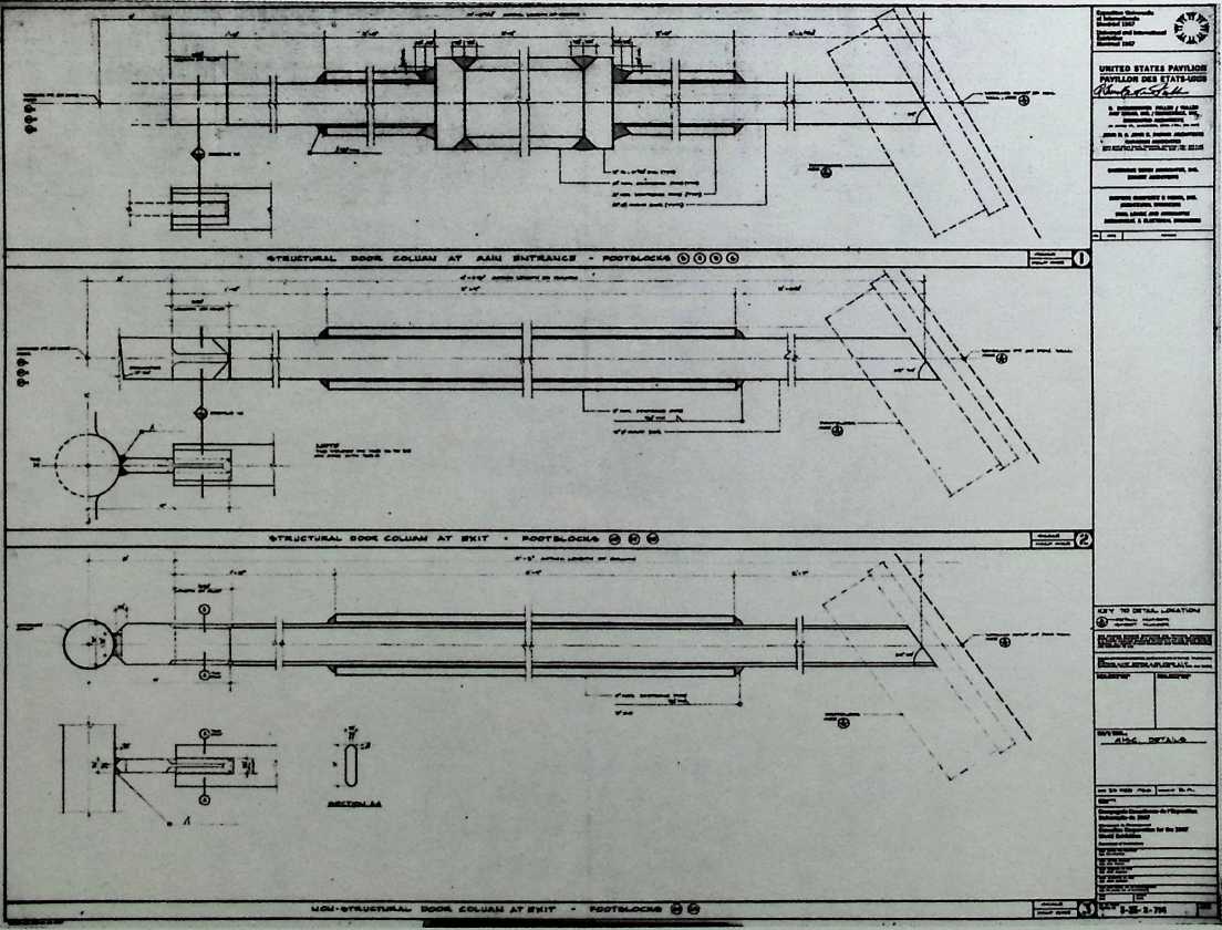
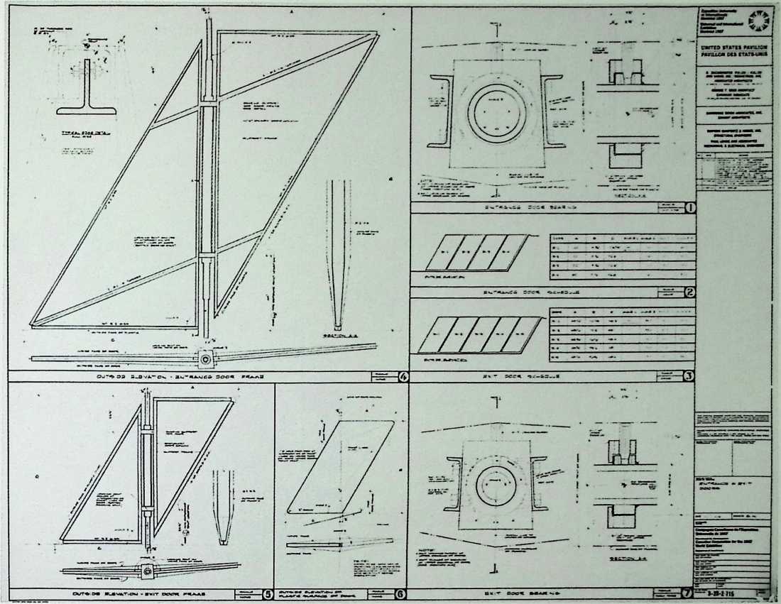
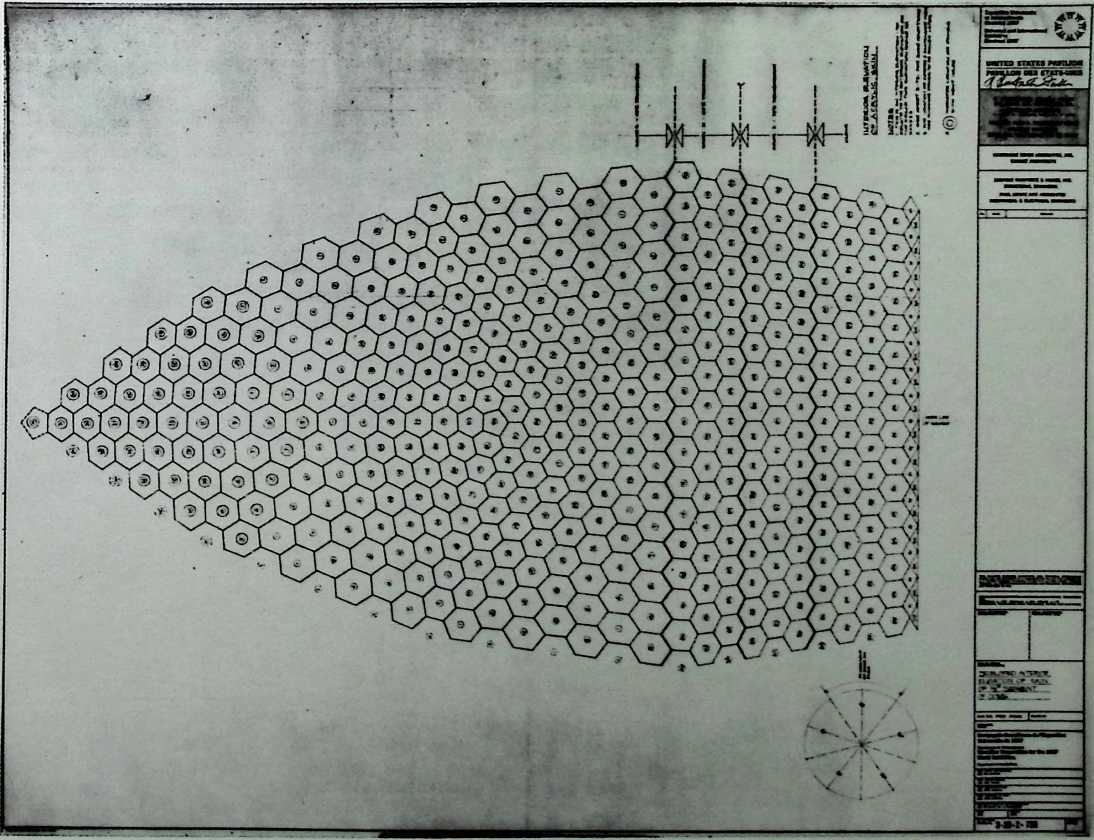
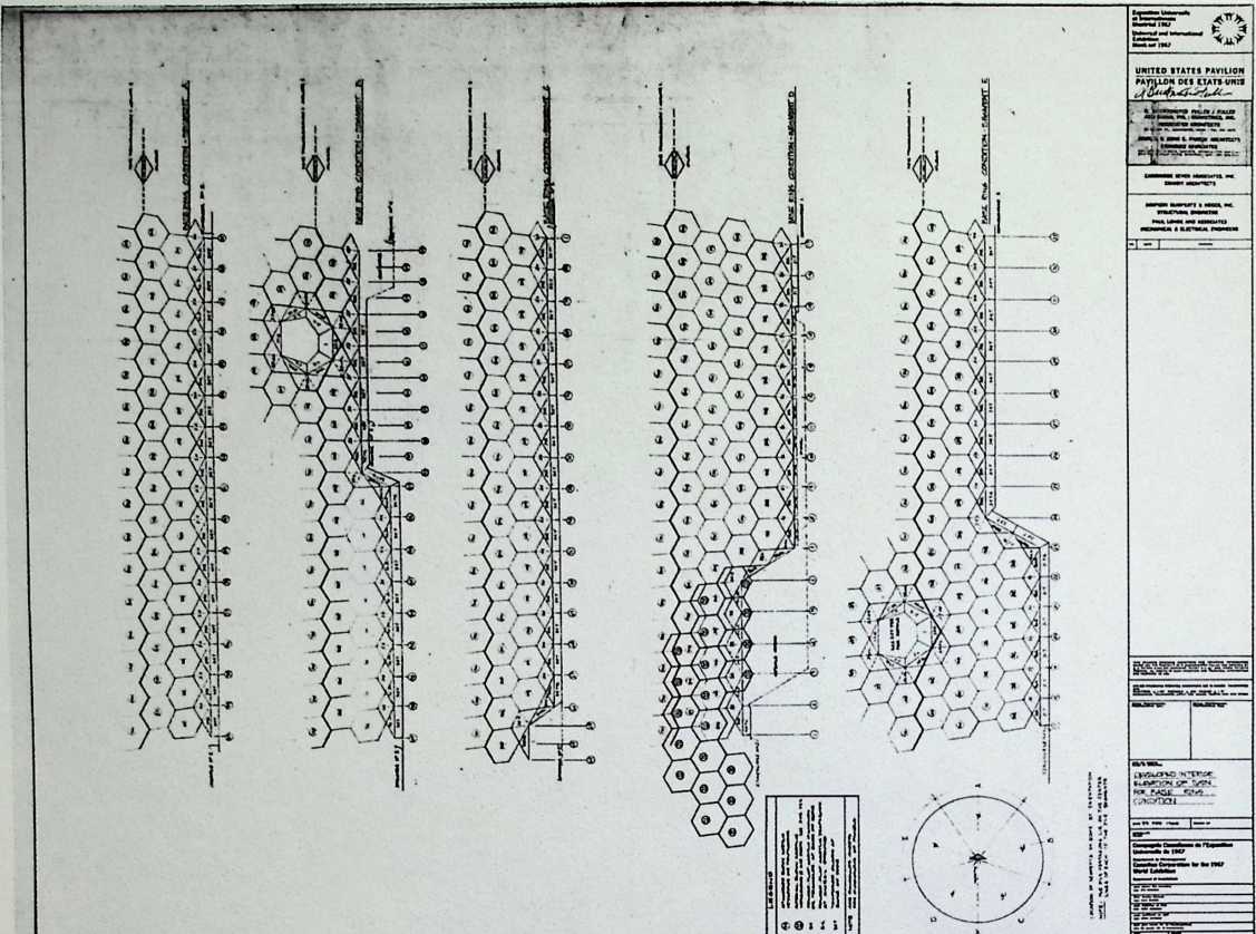
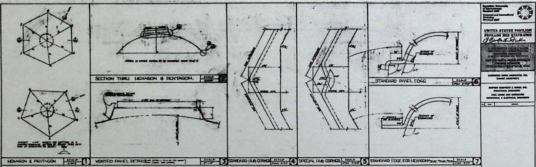
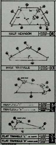
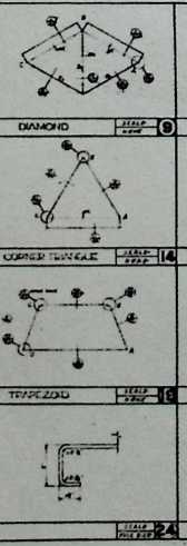
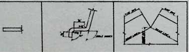
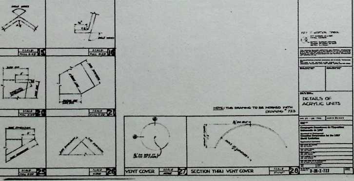
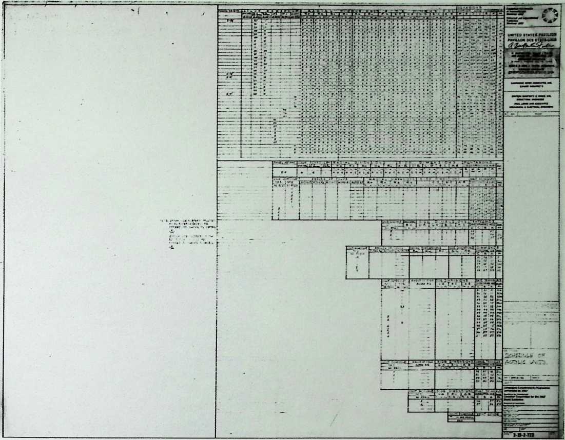
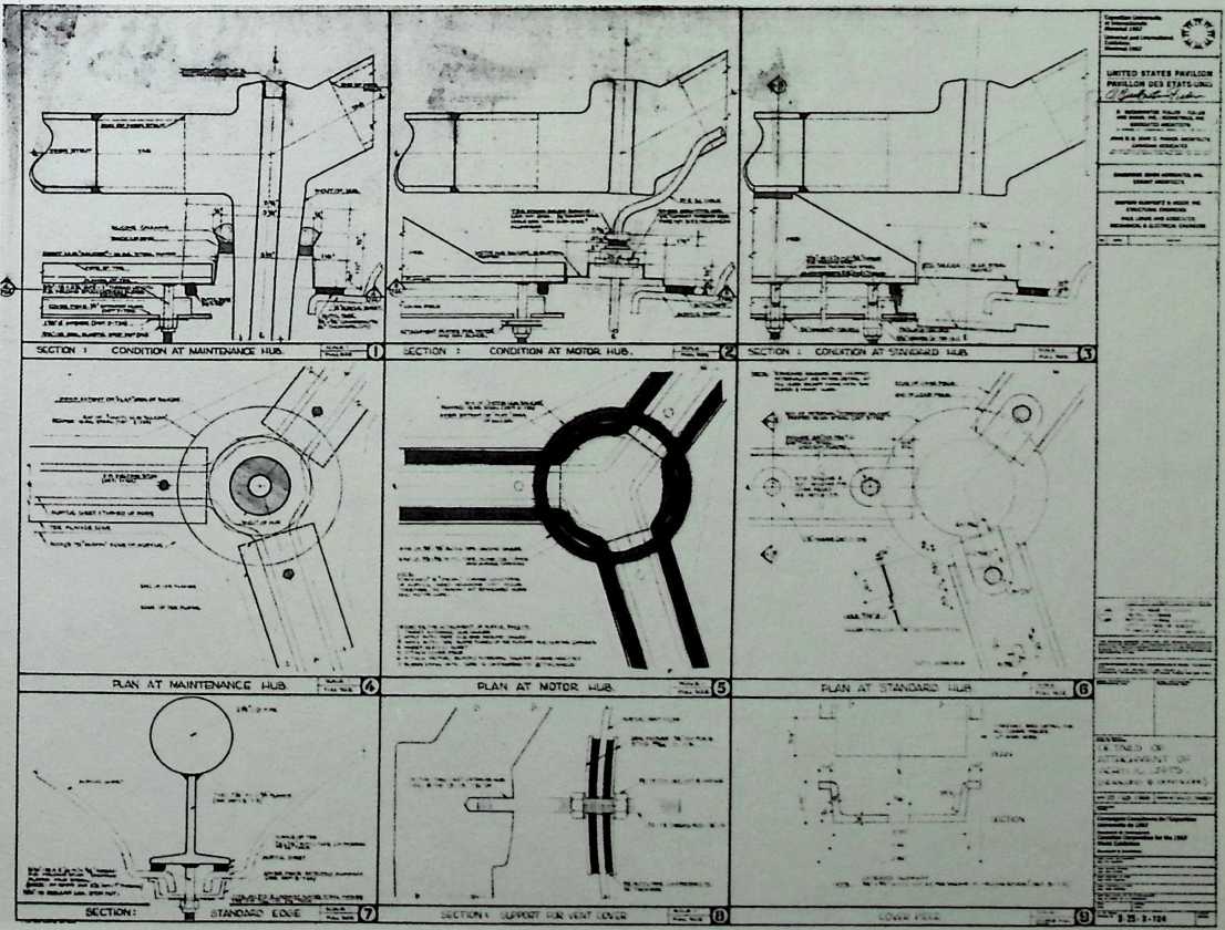
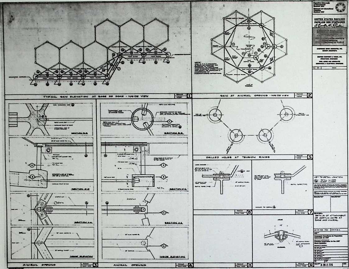
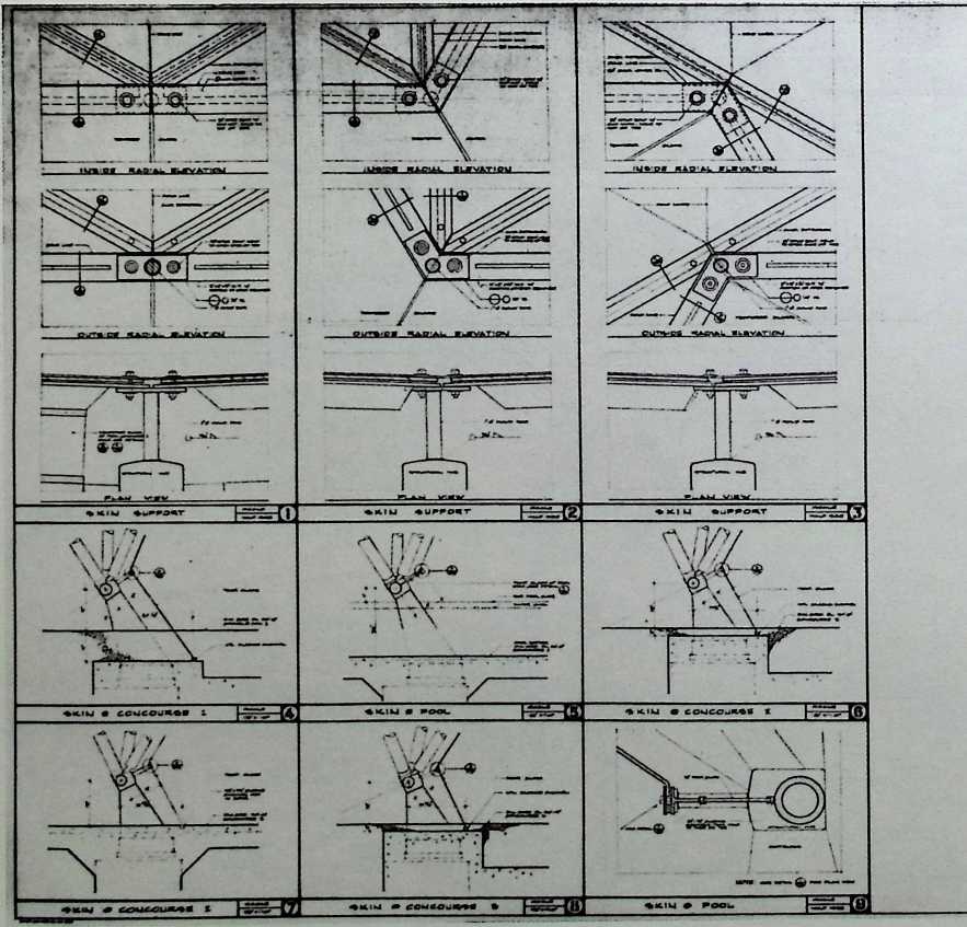
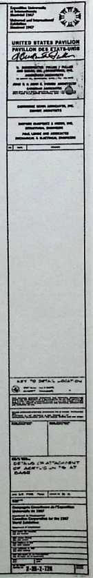
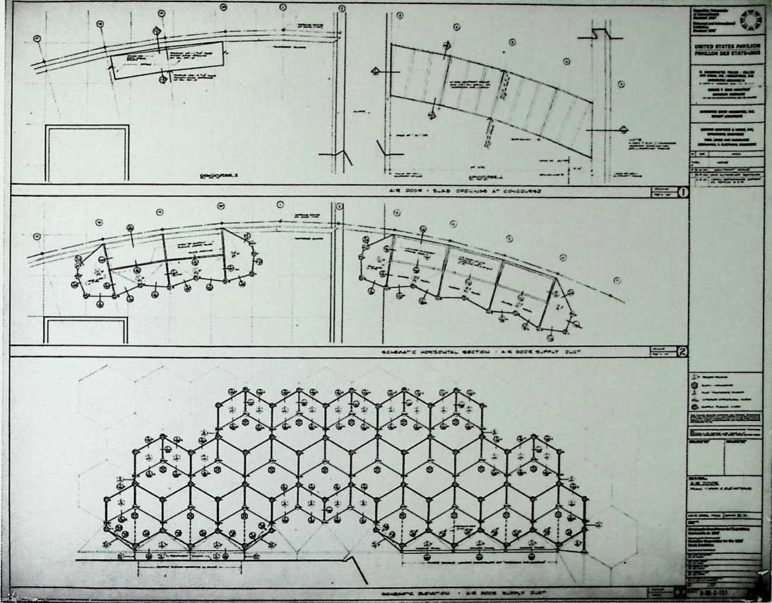
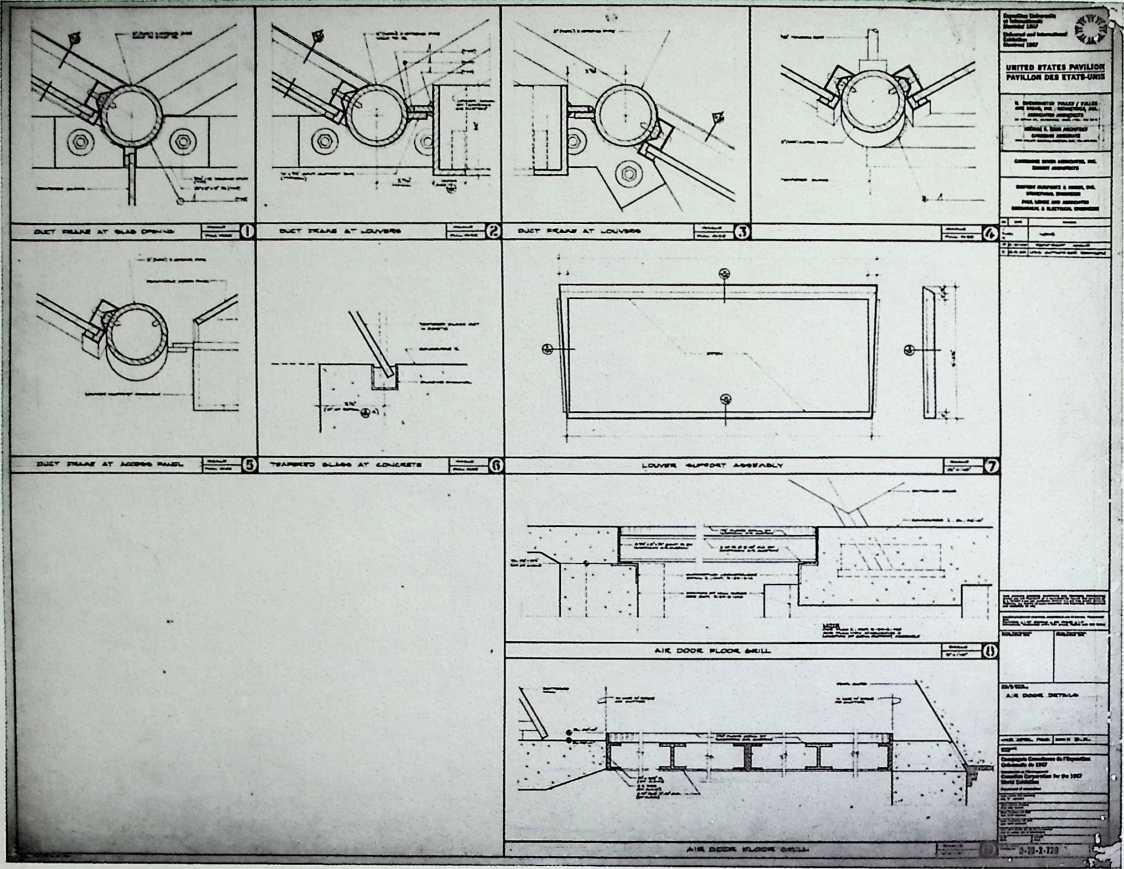
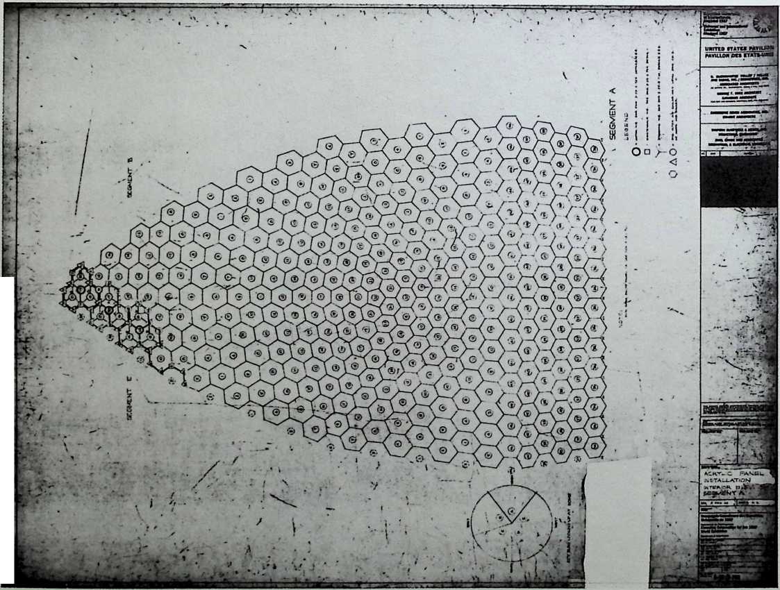
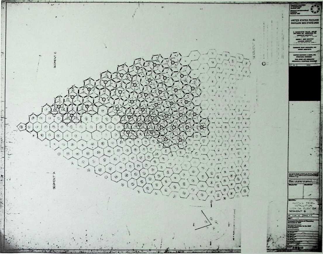
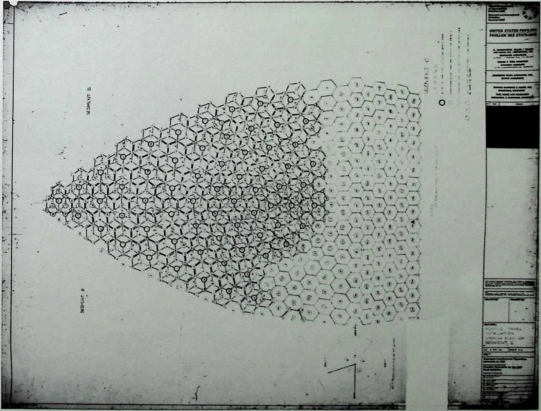
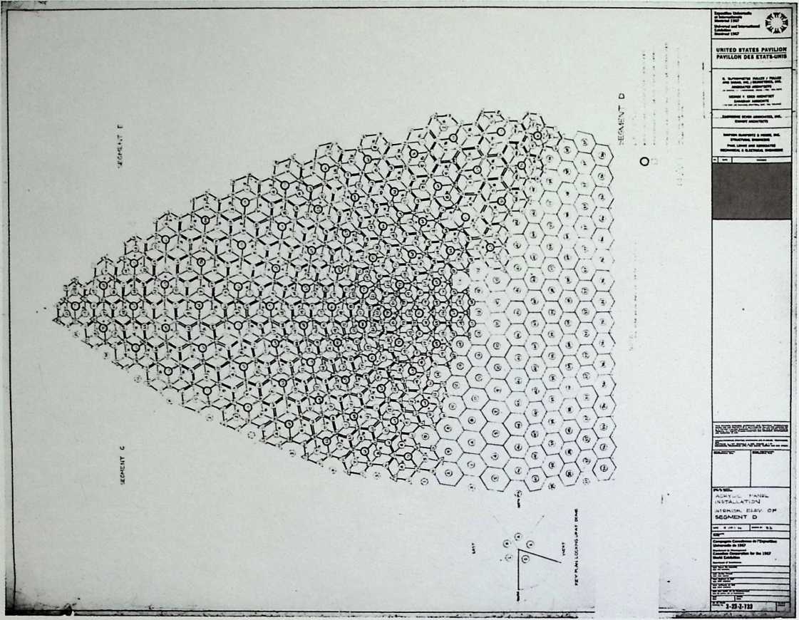
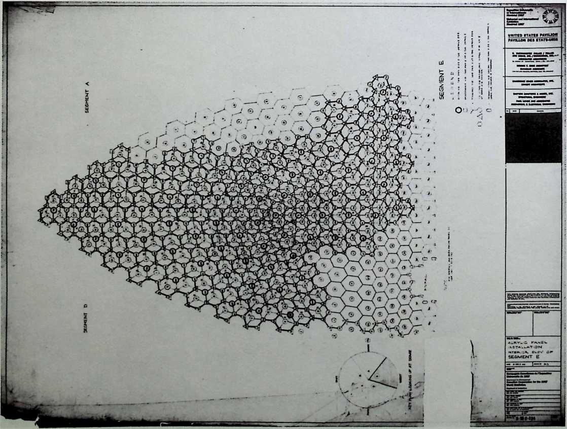
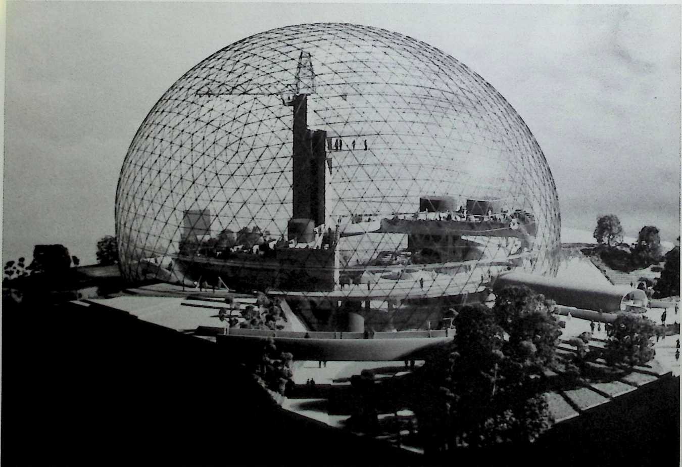
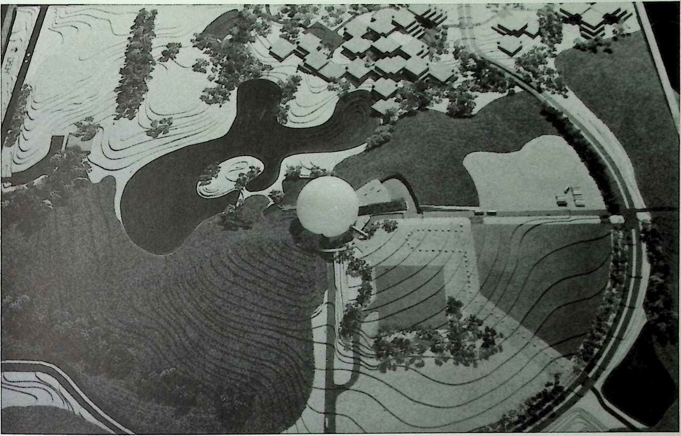
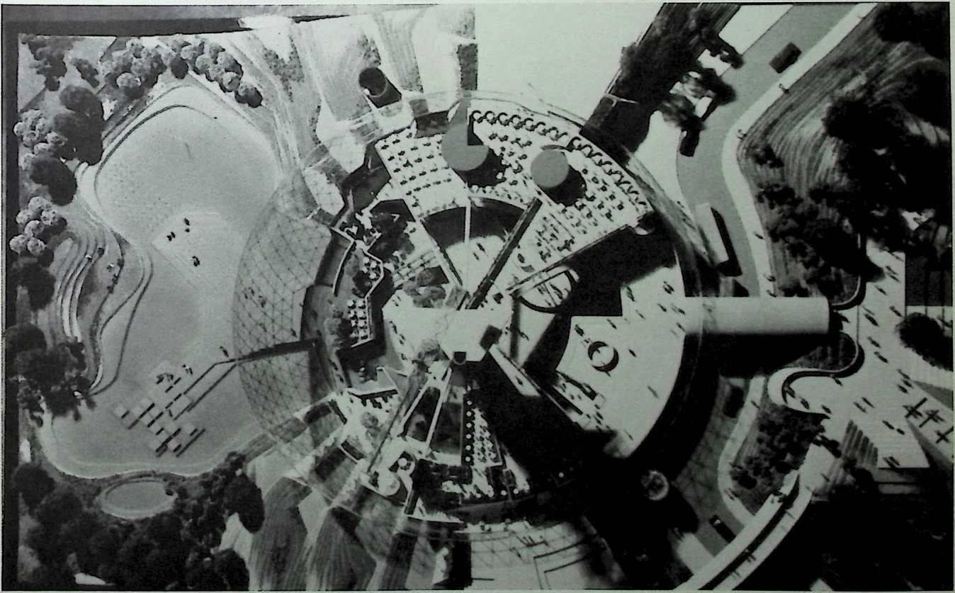
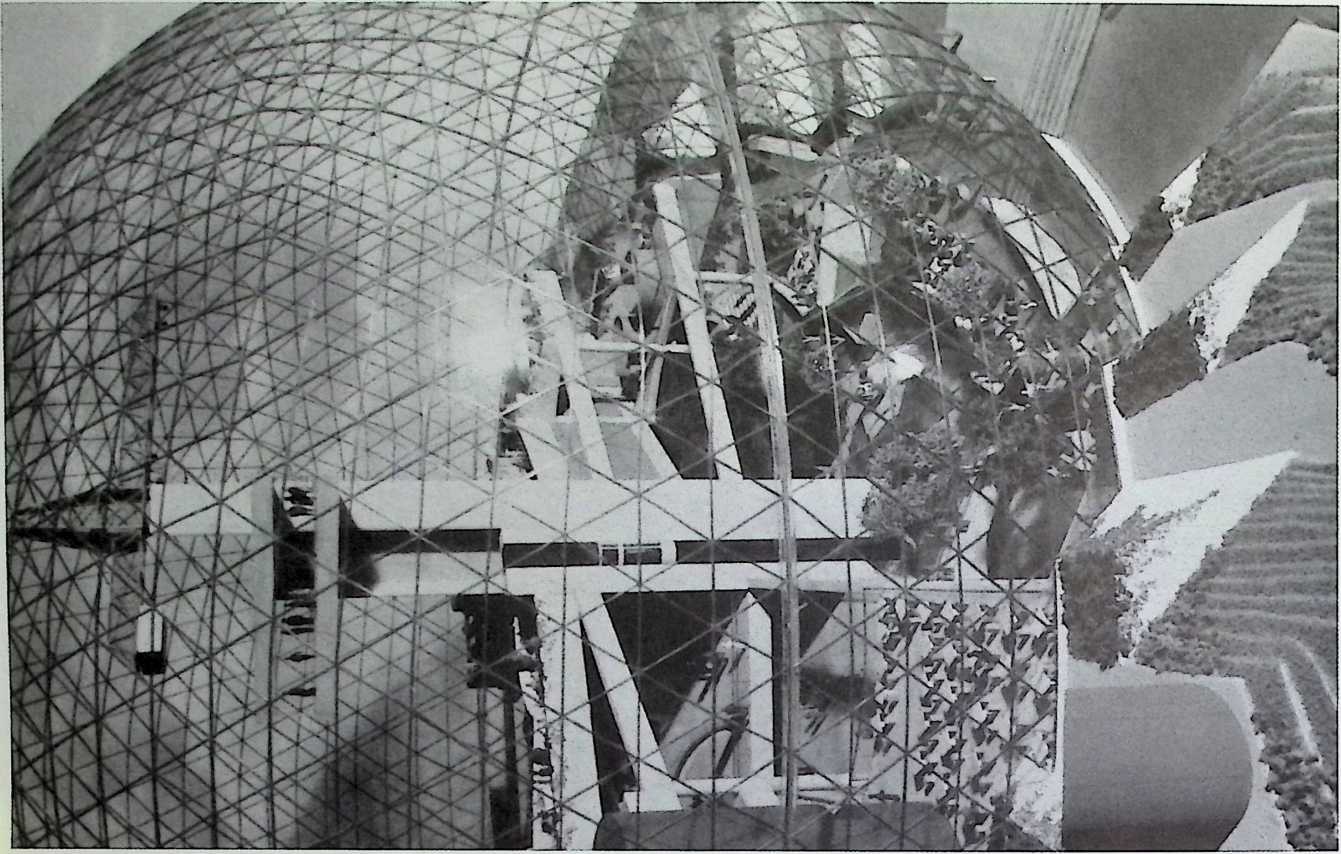
¶ Chapter 21 United States Pavilion Designed for Expo 1967, Montreal, Canada Fuller & Sadao with Geometries, Inc., 1966–1967
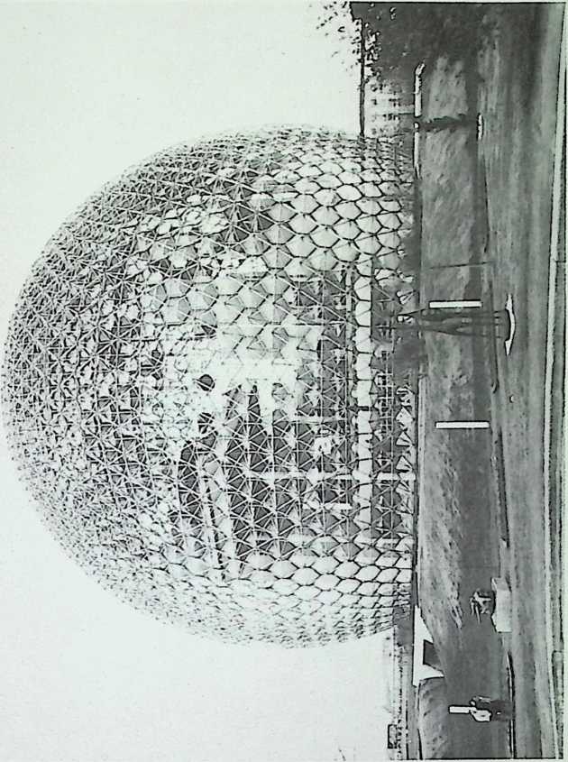
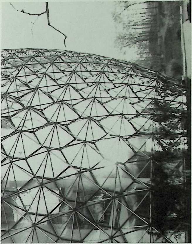
The United States Pavilion at Expo ‘67 in Montreal was the crowning commission of Fuller’s architectural career. Immediately recognized as the symbol of this international fair, the geodesic dome assumed a position on the vanguard of modern design that it had not known since its invention in the late forties. It was conceived as a totally dynamic structure, through which a throng of people were guided on escalators to the various levels of the exhibition. On the outside, one could observe the monorail as it penetrated the glistening acrylic skin of the dome, which was outfitted with triangular shades that were to close automatically in accordance with a computerized scheme reflecting the path of the sun. The structure is the star tensegrity truss that had been perfected during the mid-1960s.


rnumnm
fciinu |
|
£2mTiW7 |
|
URITED STATES PAVIUOM PAY1LLON DES ETATS-UMiS
UNITED STATES PAVIUON PAVILLON DES ETATS-UNIS
![]()
■
112 THE GEODESIC REVOLUTION, P/VRT 2
UMTTXO STATU myillm mi rfiruiKfi
![]()

1tin

wk- |
||
Th--- - |
||
—"i-ai-ui l~
ii
![]()
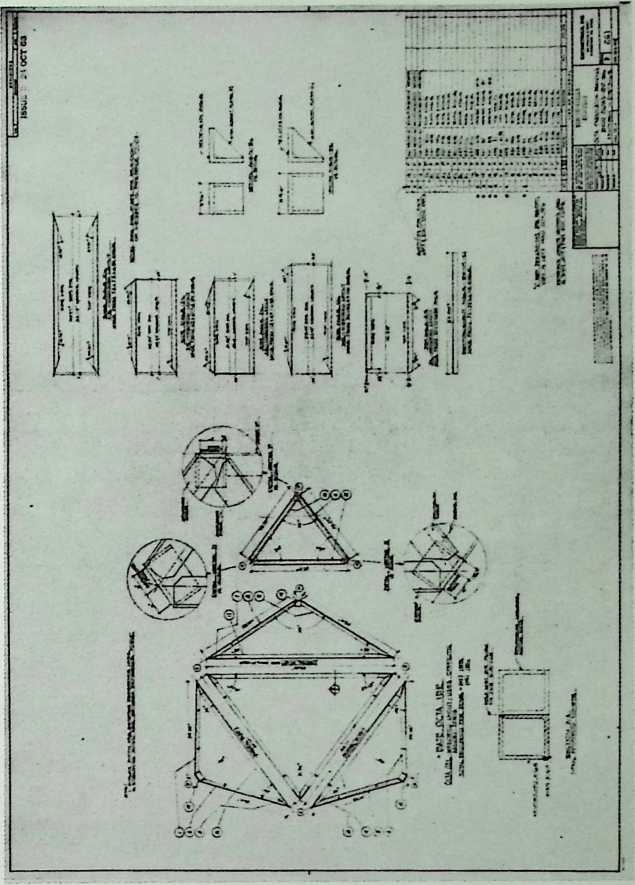
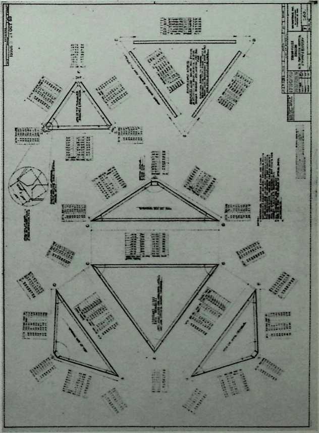
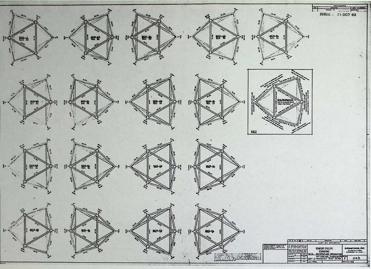
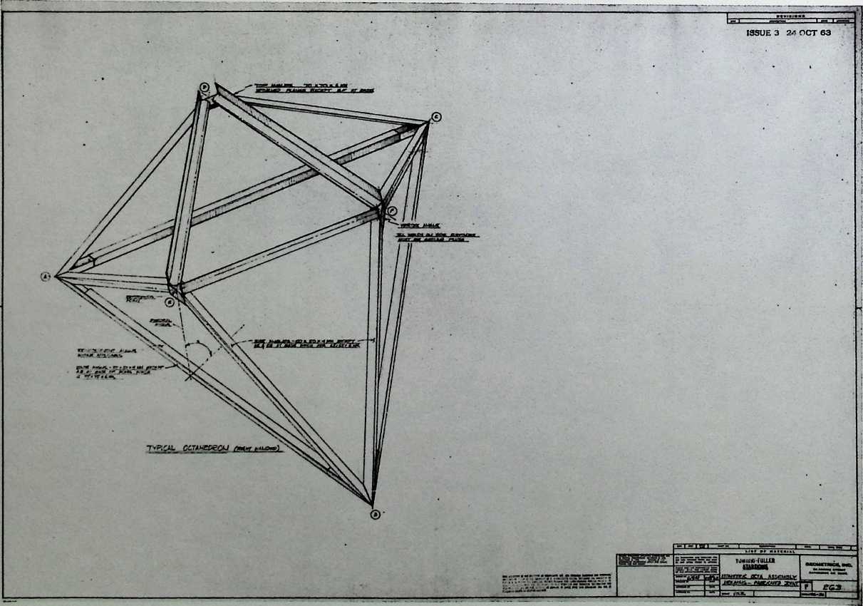
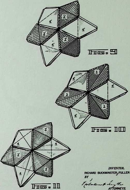
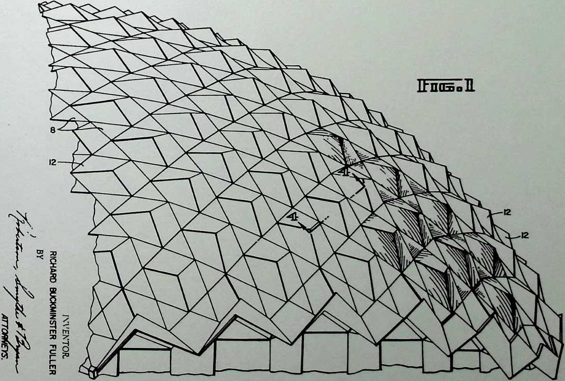
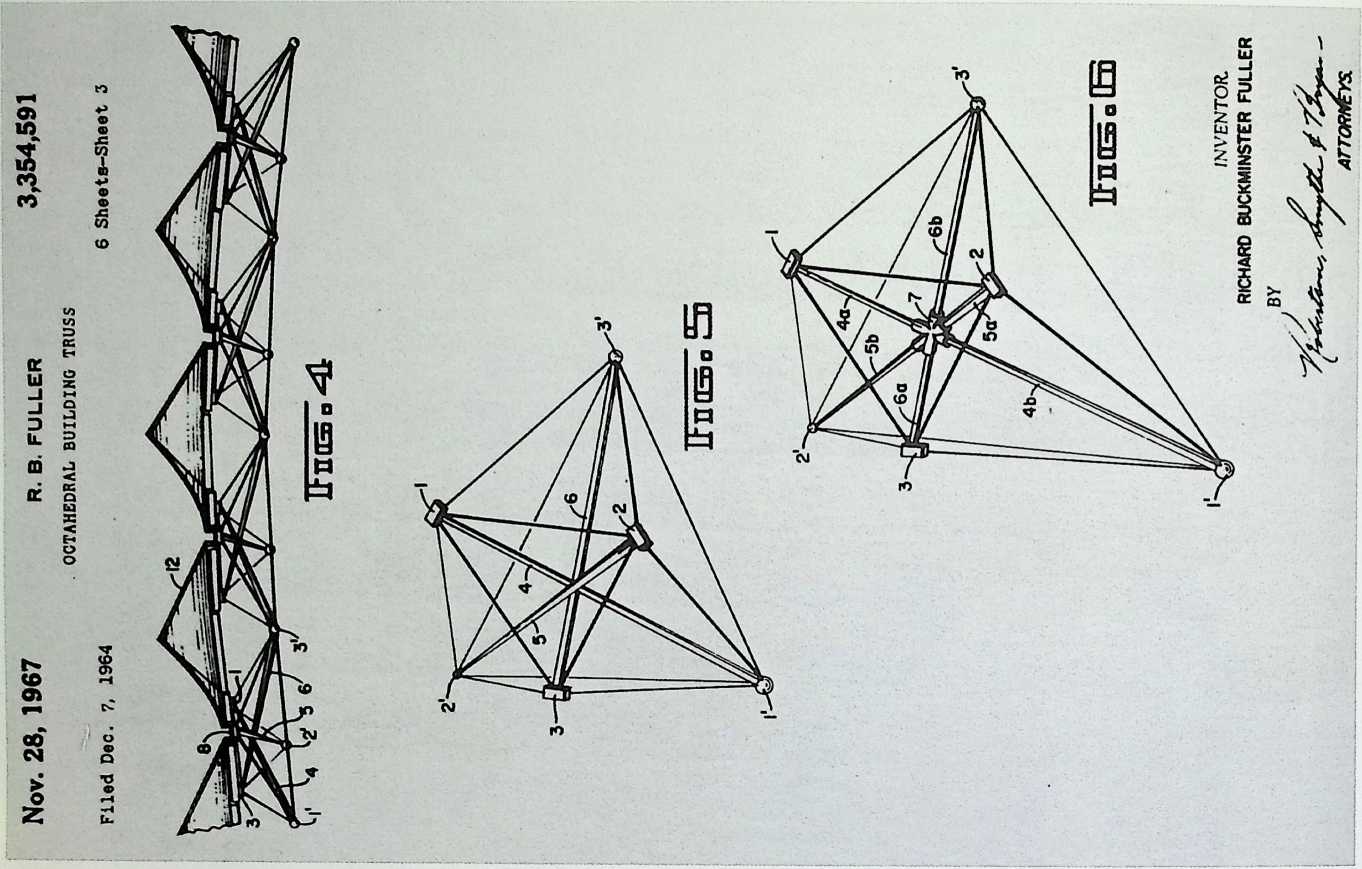
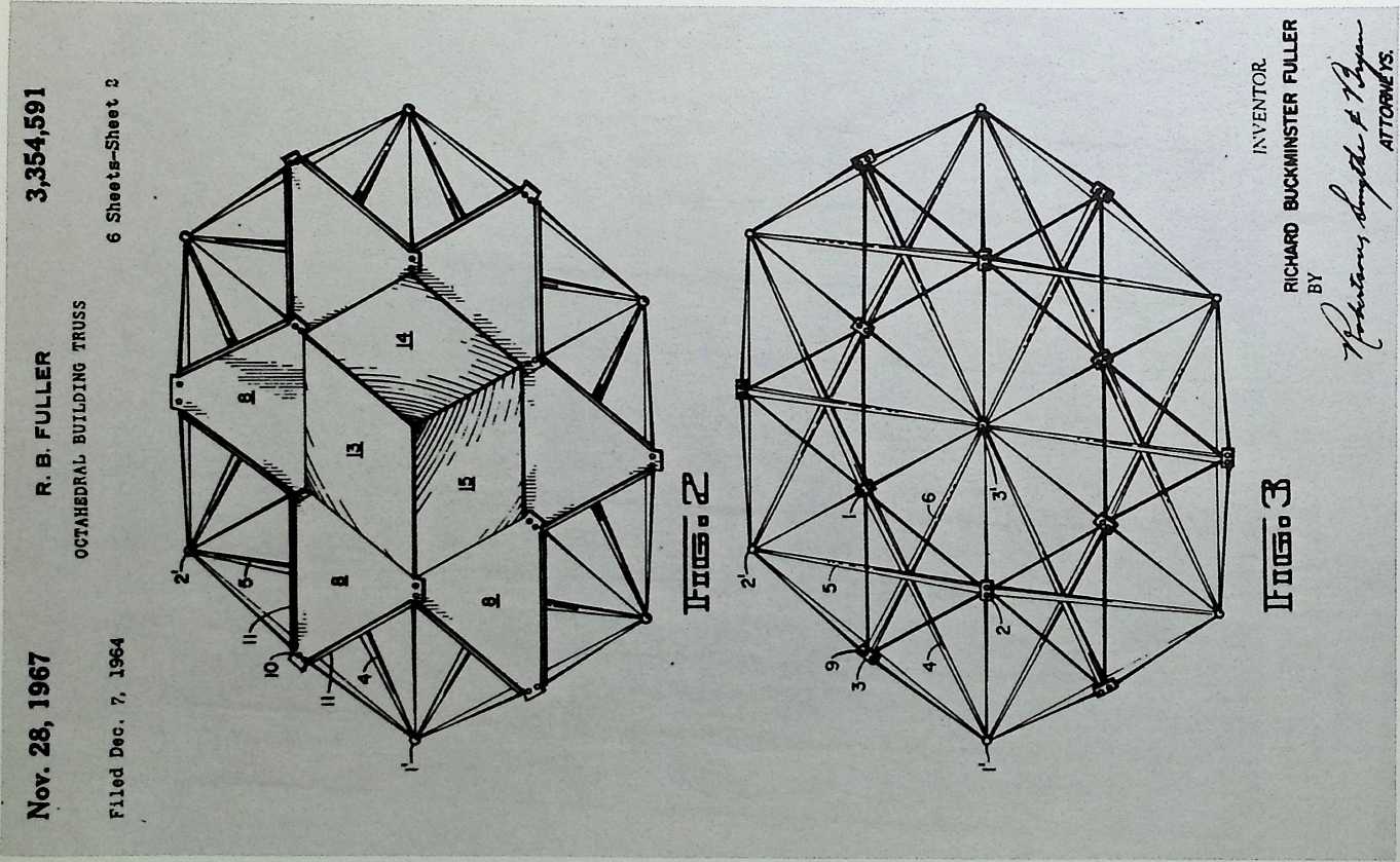
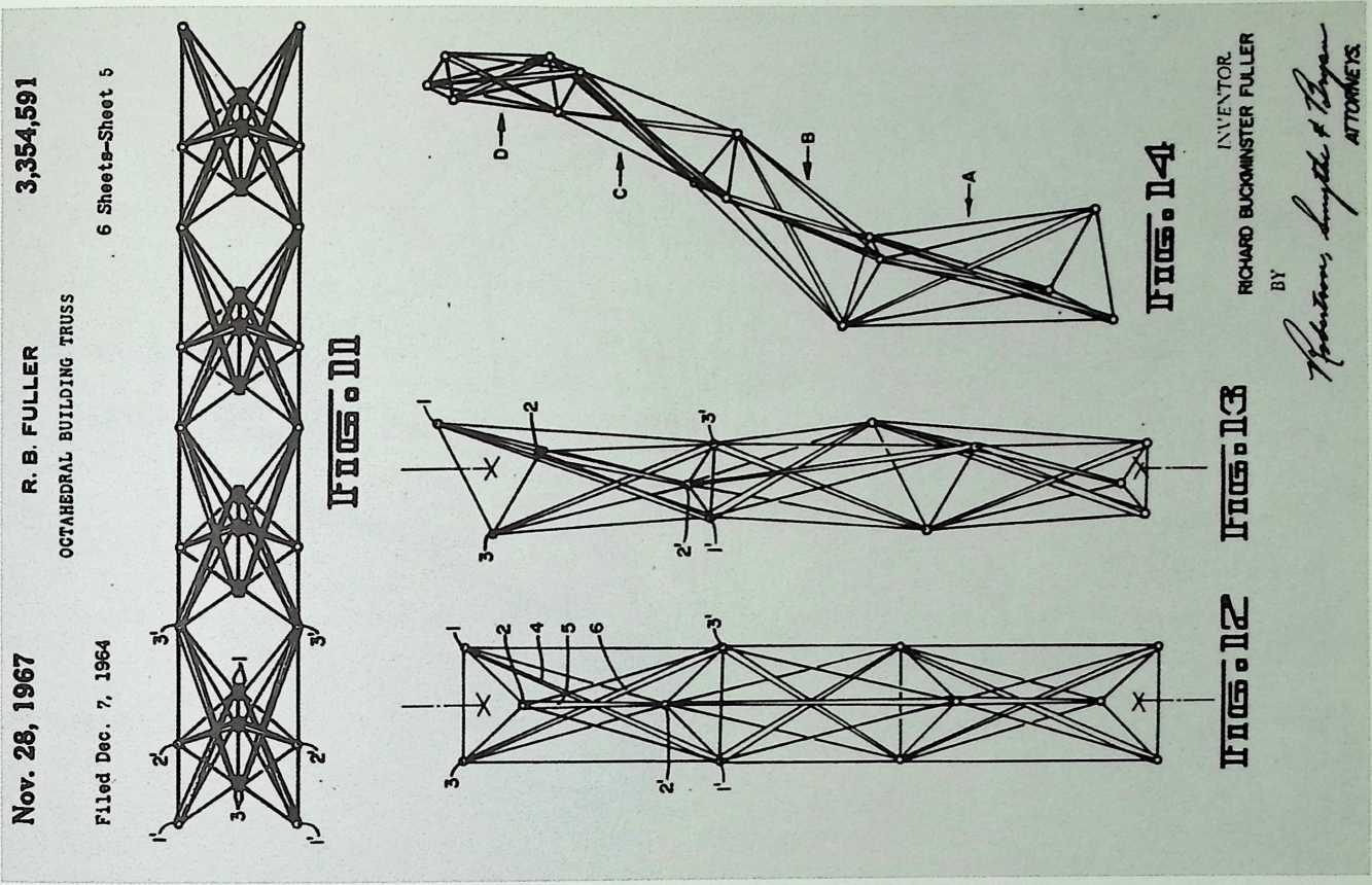
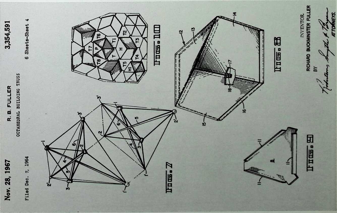
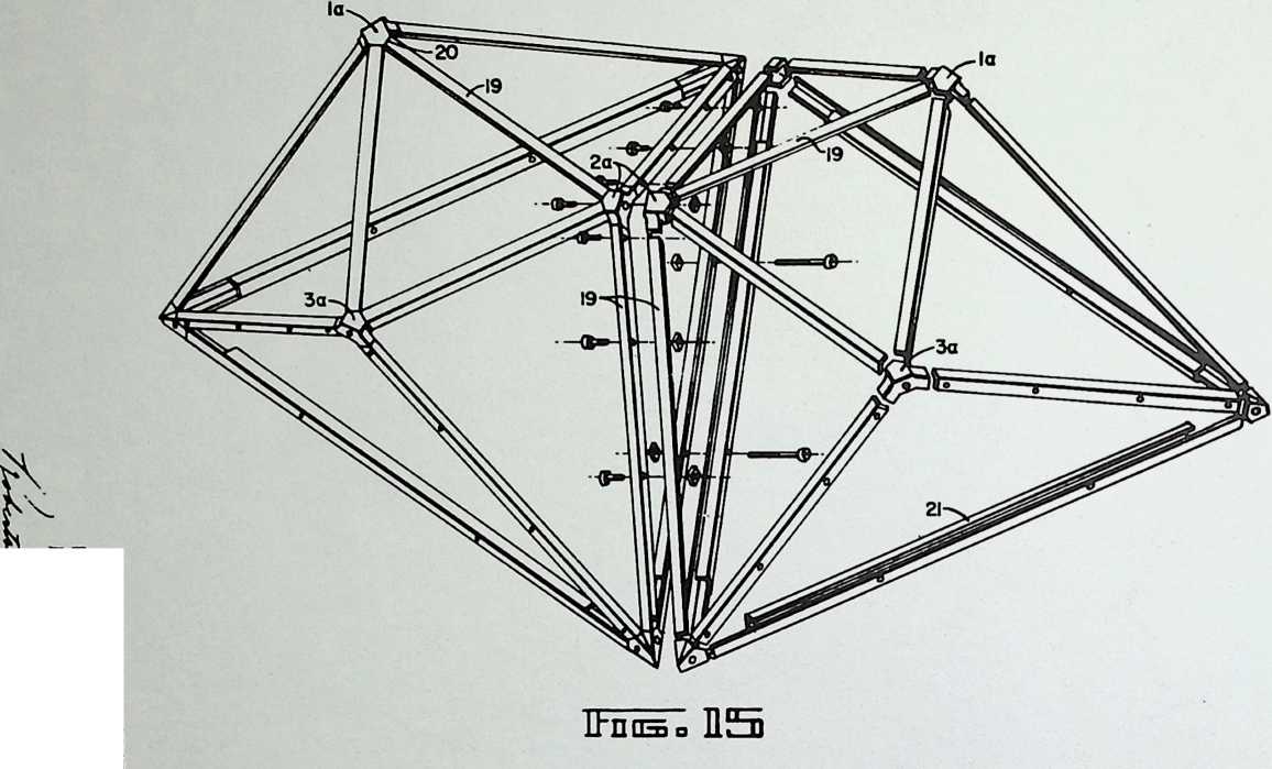
Star Tensegrity Octahedral
Truss Patent
11/28/67
The advantage of the star tensegrity octahedral truss is that the outer edges of the octahedron are tensegrity cables held in place by three crossbars on the interior. By adjusting these bars, the outer configuration of the octahedron presumably could be an infinite variety of shapes using the same crossbars.
2 o
to
<o
3
![]()
![]()
INVENTOR.
RICHARD BUCKMINSTER FULLER
bO QO
gj
■n c
fn XI
![]()
![]()
![]()
![]()
‘‘Bale Bunder Windhu
The function of this dome is not known.
Anne Bali Ubud
Campuan’’ Dome 1967
World Man Center
Conference Building,
Cyprus
Fuller & Sadao, 1967
The World Man Center was designed to be the central landmark of the World Center, a parcel of land that was to have no national identity. Thus, the geodesic globe was a relevant symbol for the center of a unified planet. It encloses a cultural center building. Bungalows designed for the Mediterranean climate cascade down a hill at the base of the dome. These architectural elements are the work of Sadao and Karlis Grinbergs.
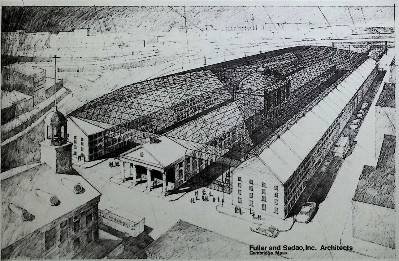
Fuller and Sadao, inc.
Architects
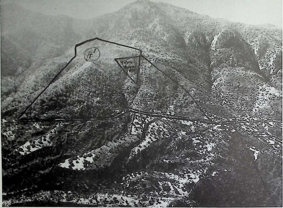
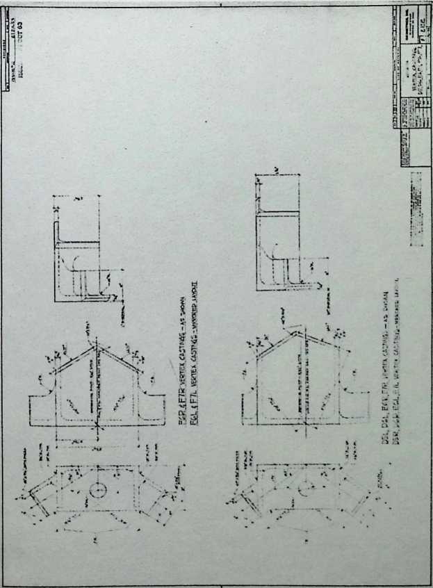
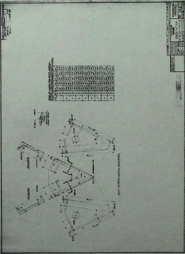
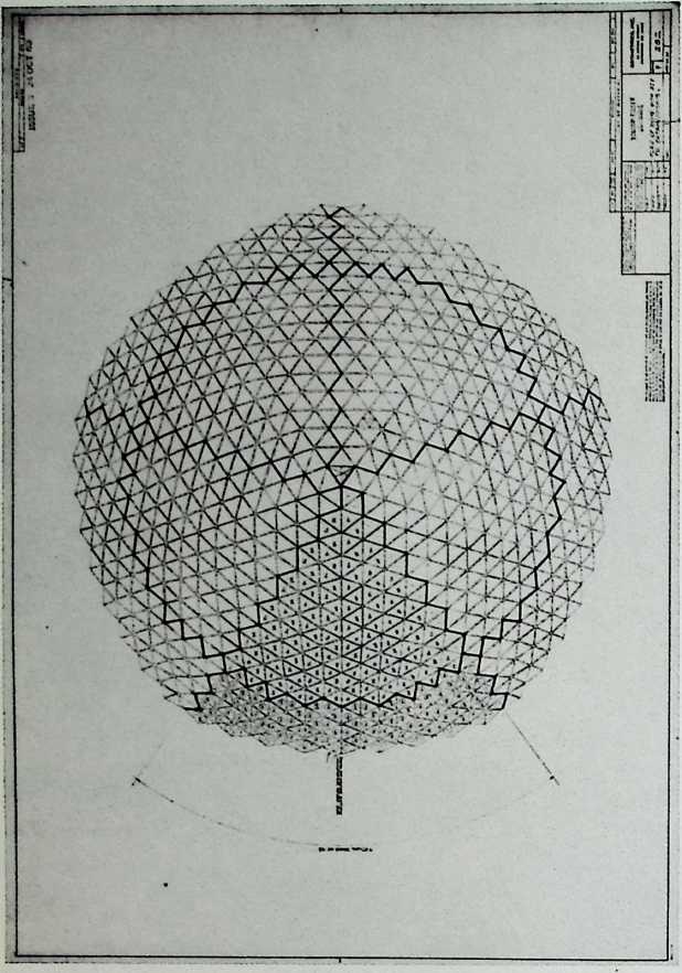
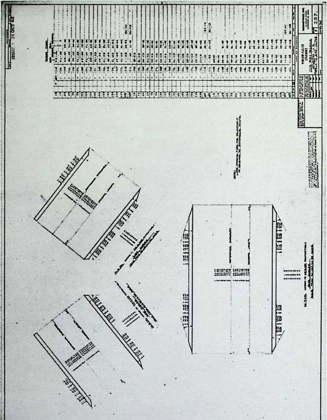
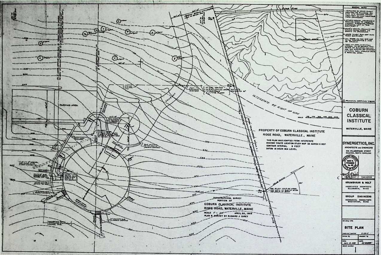
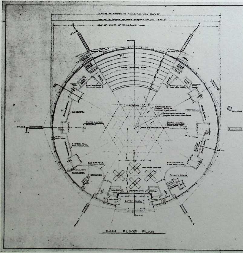
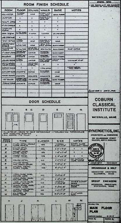
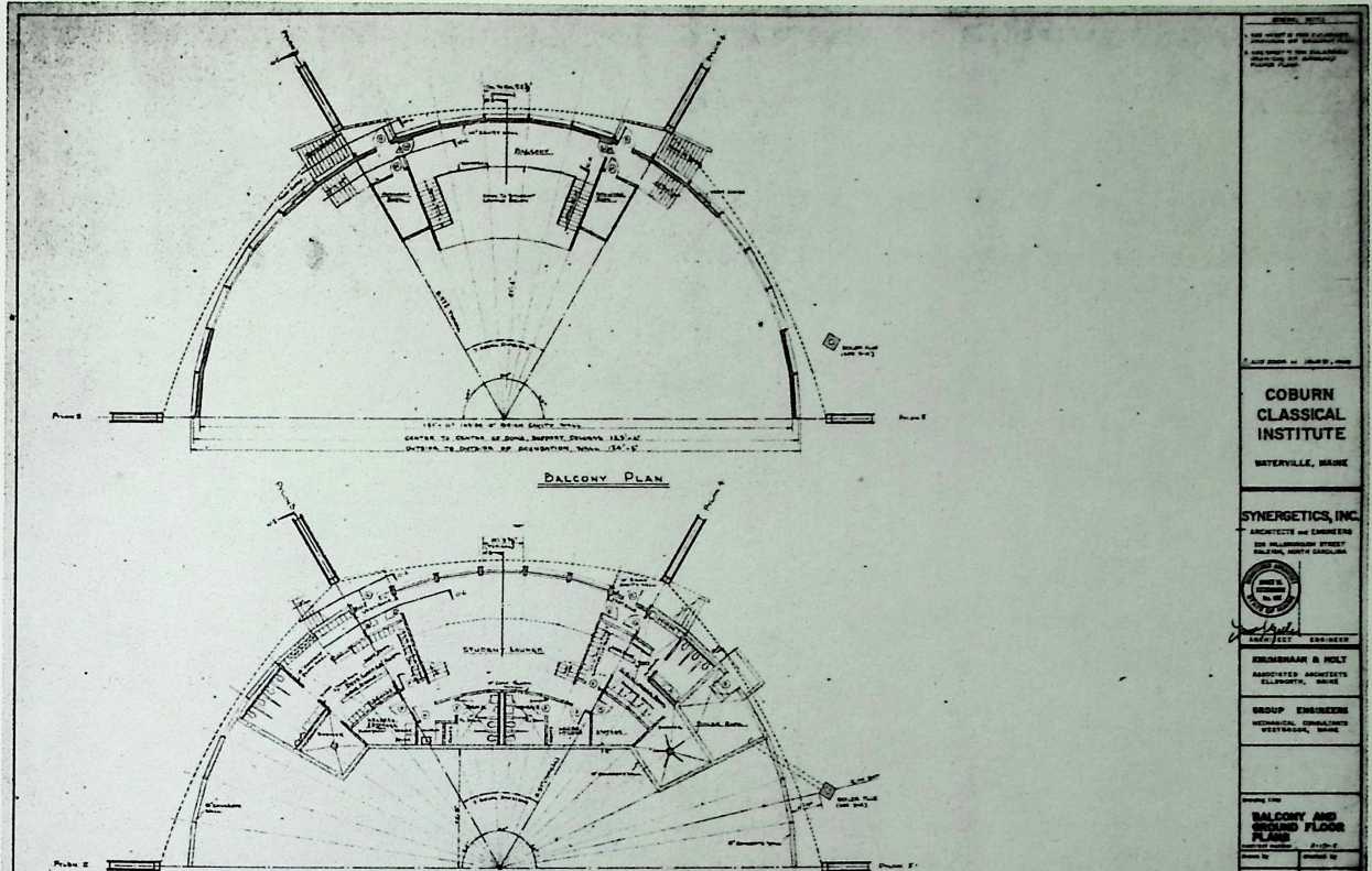
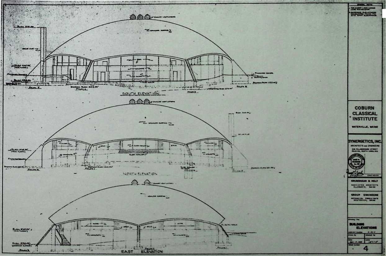
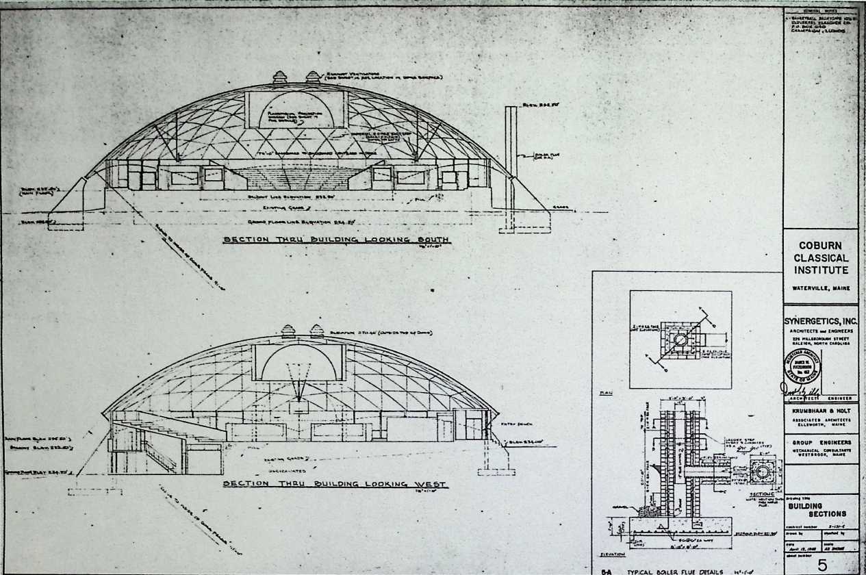
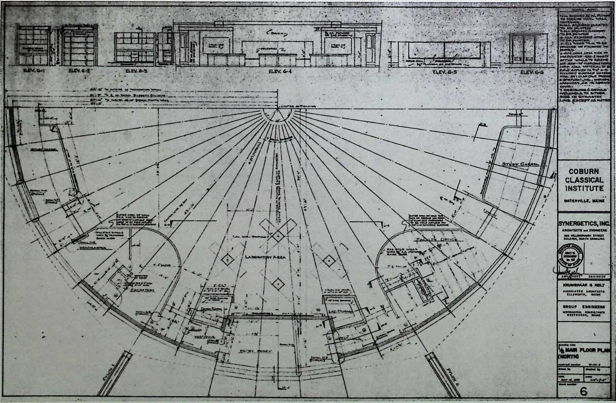
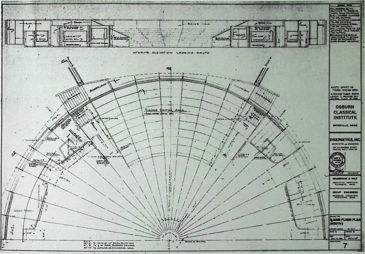
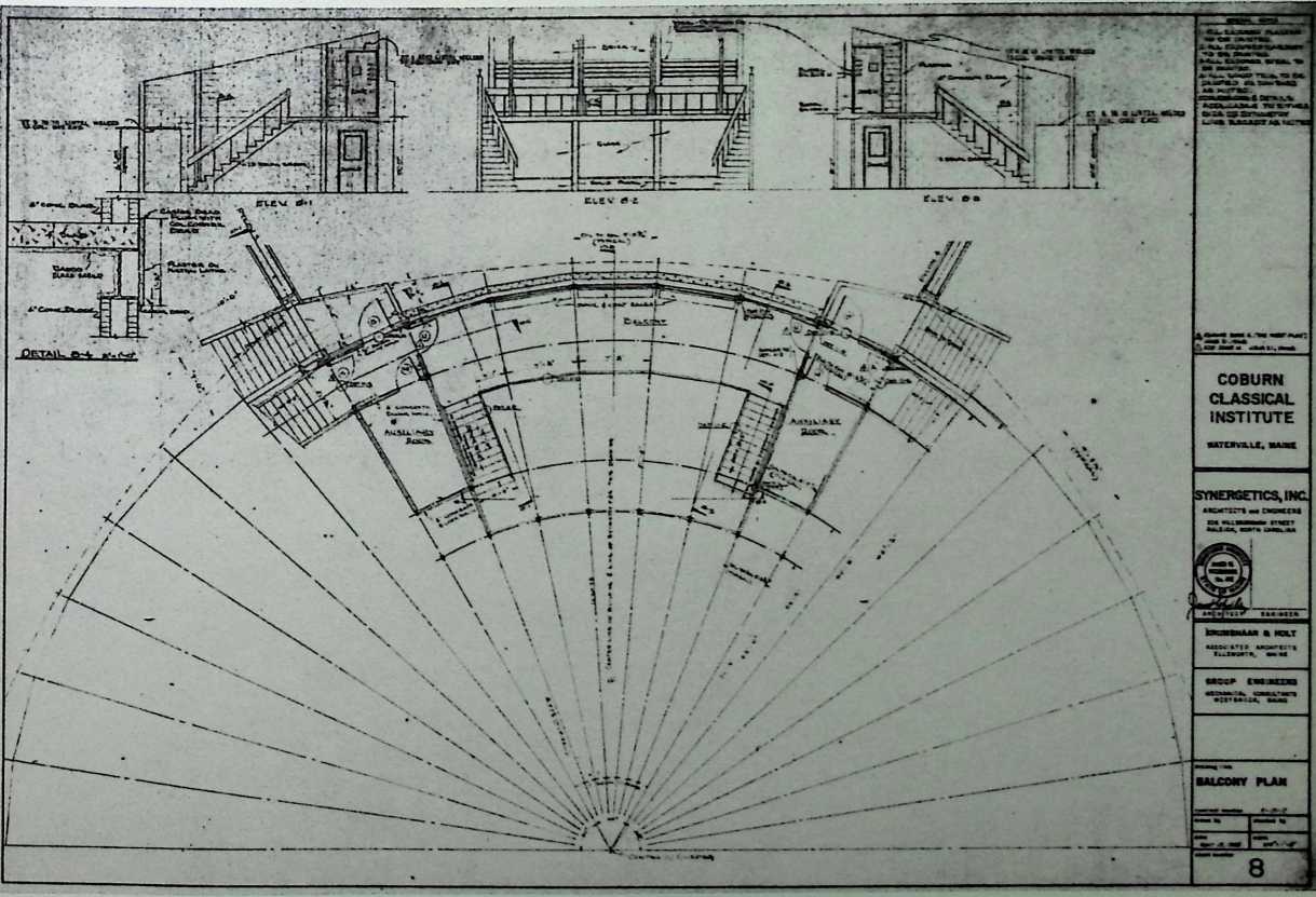
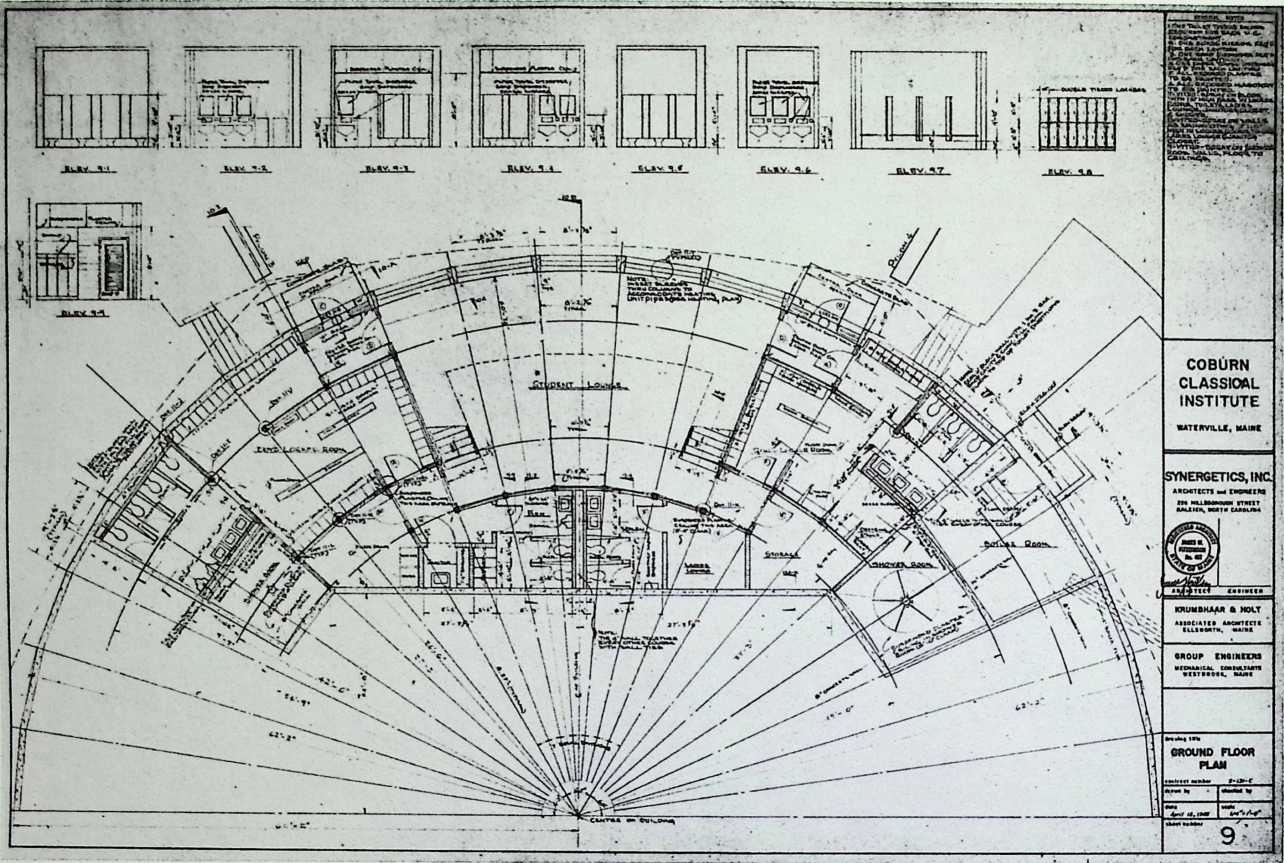
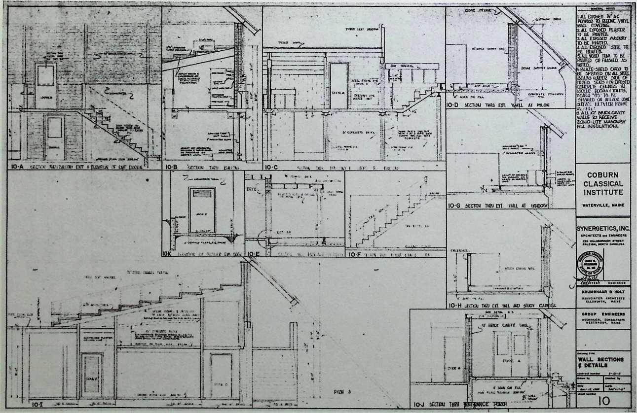
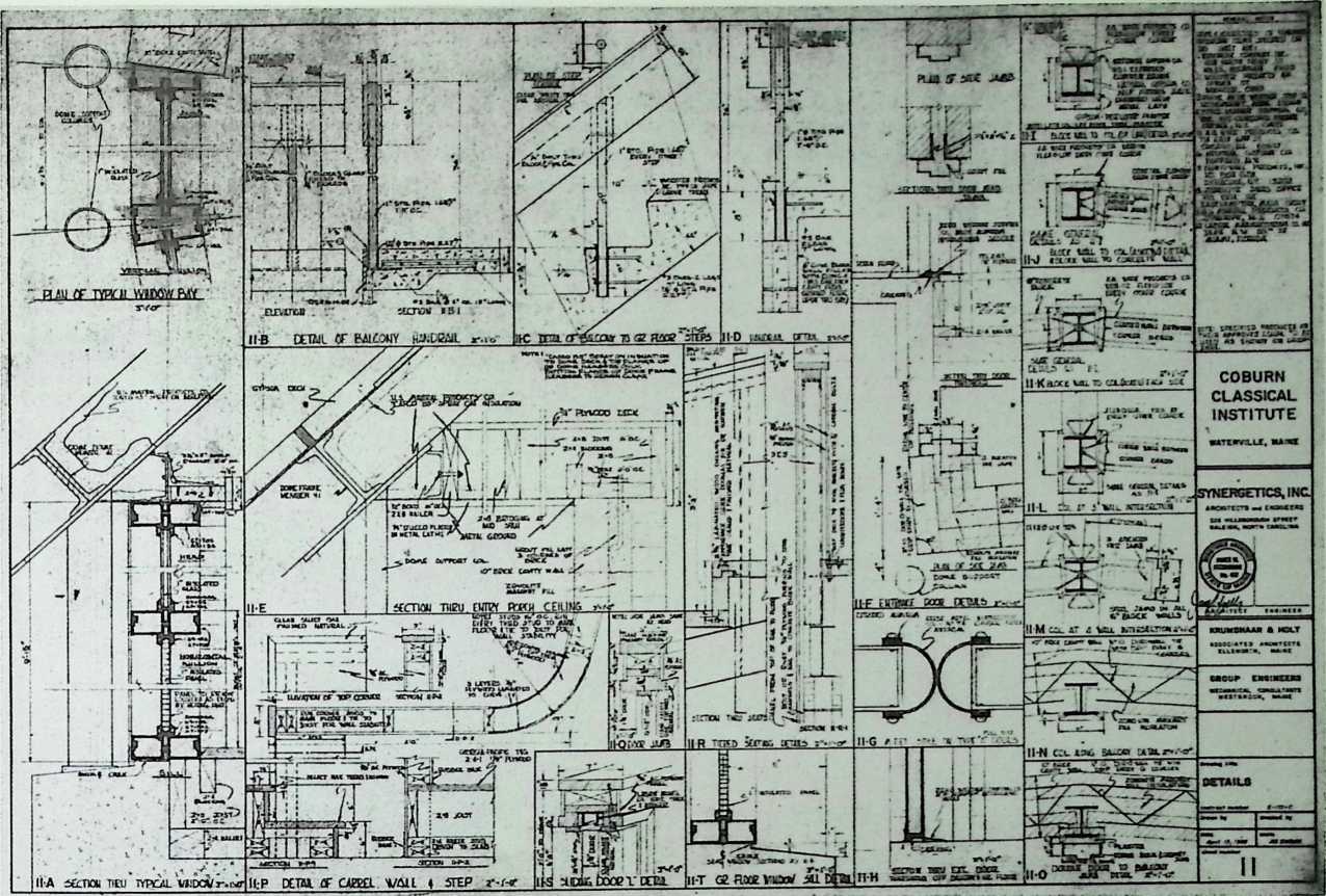
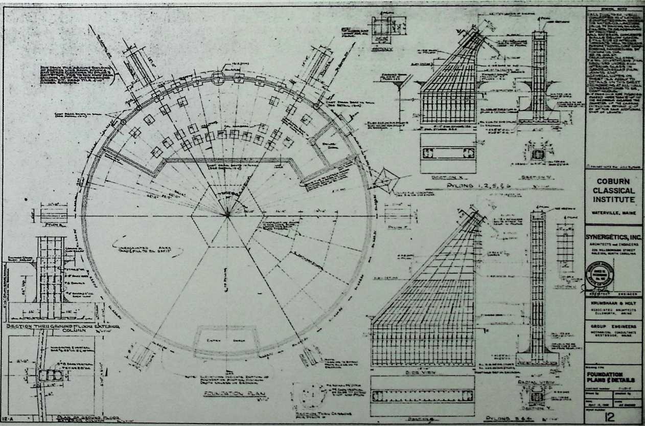
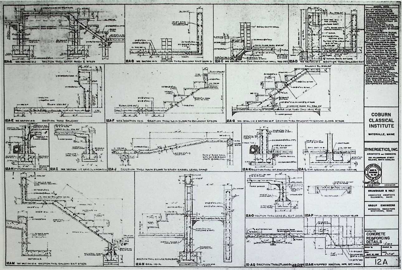
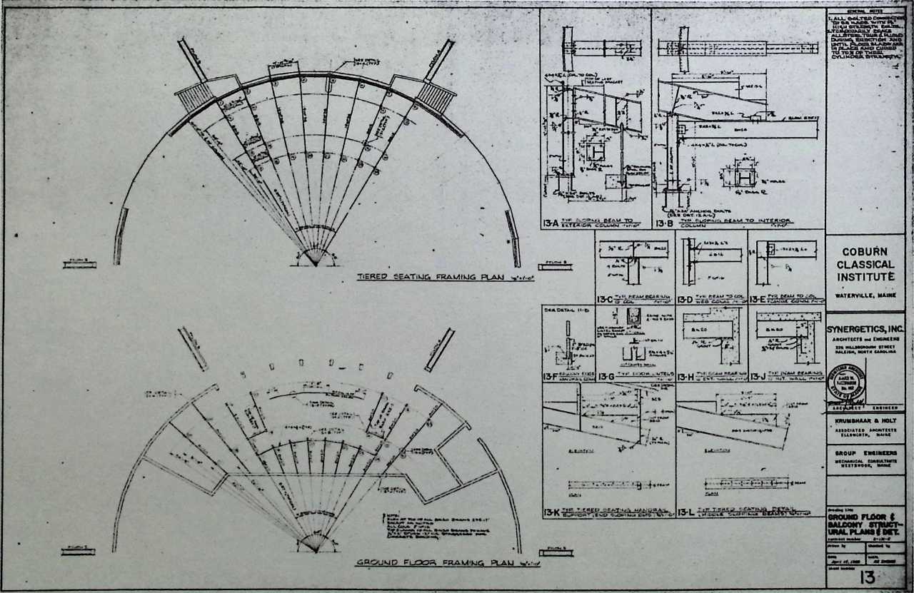
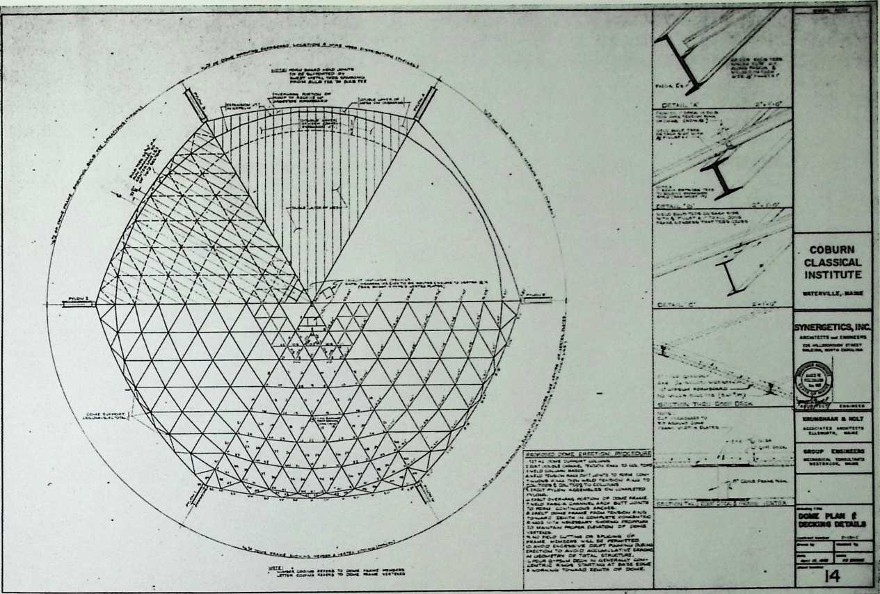
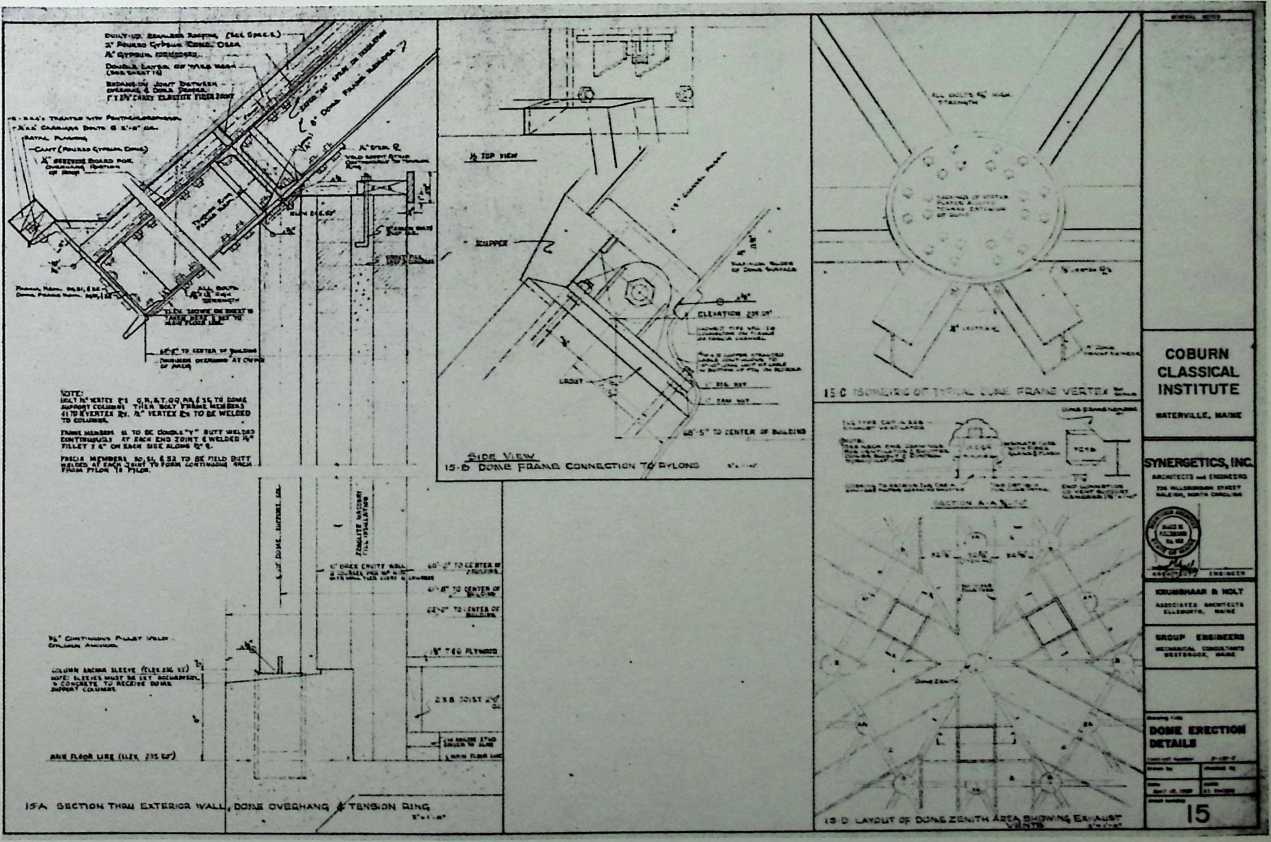
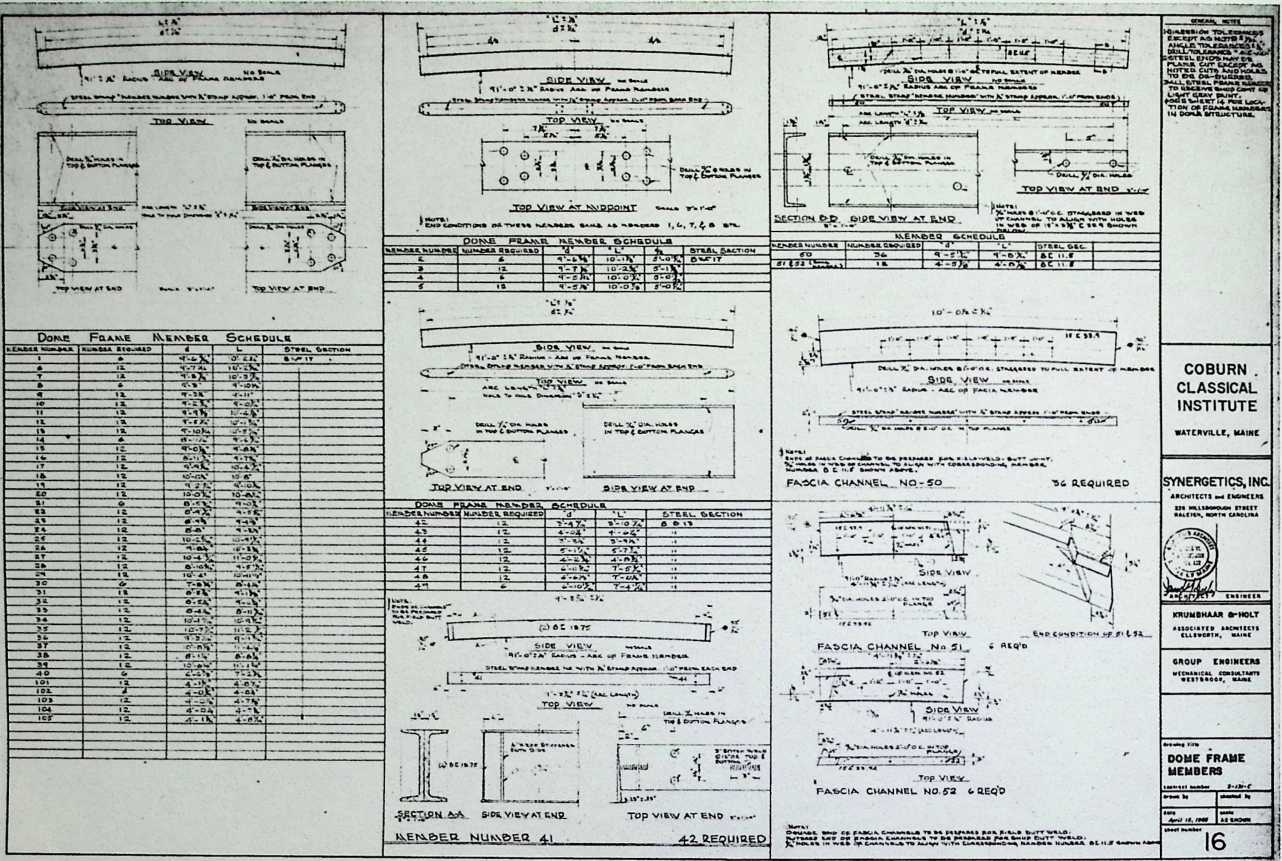
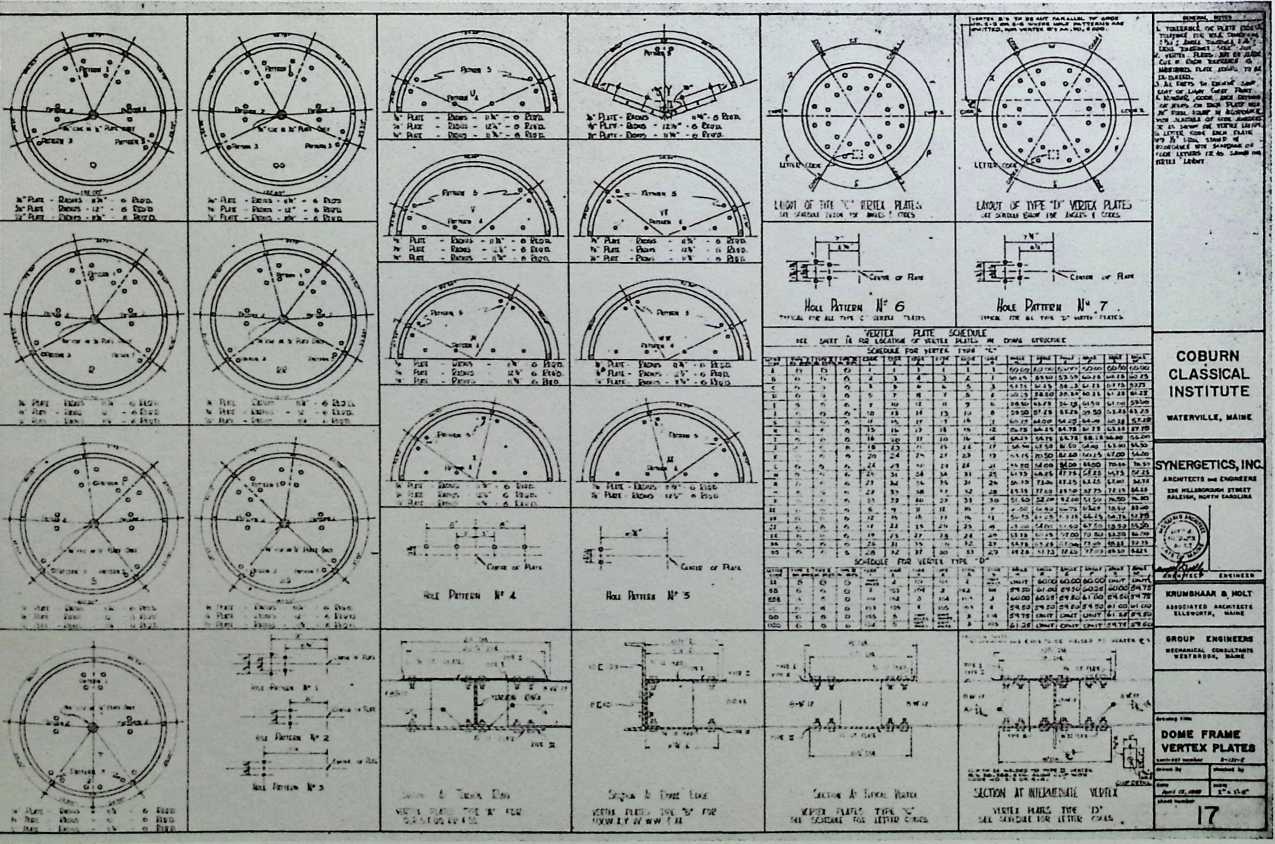
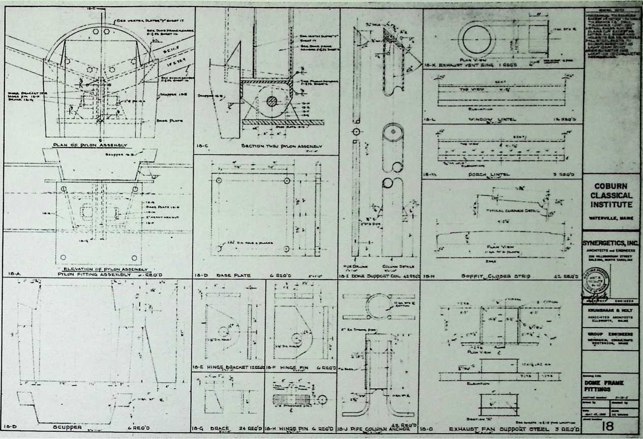
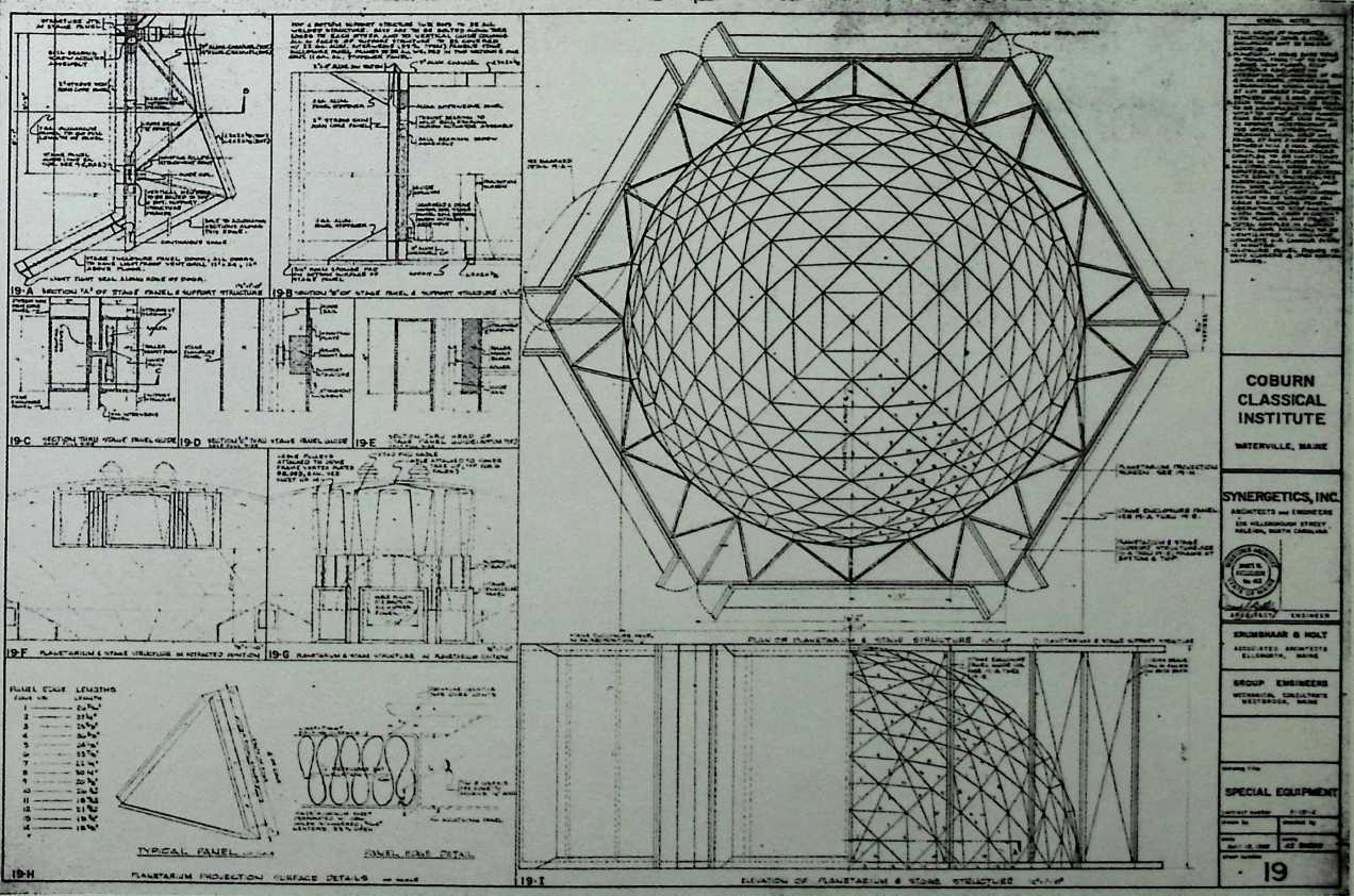
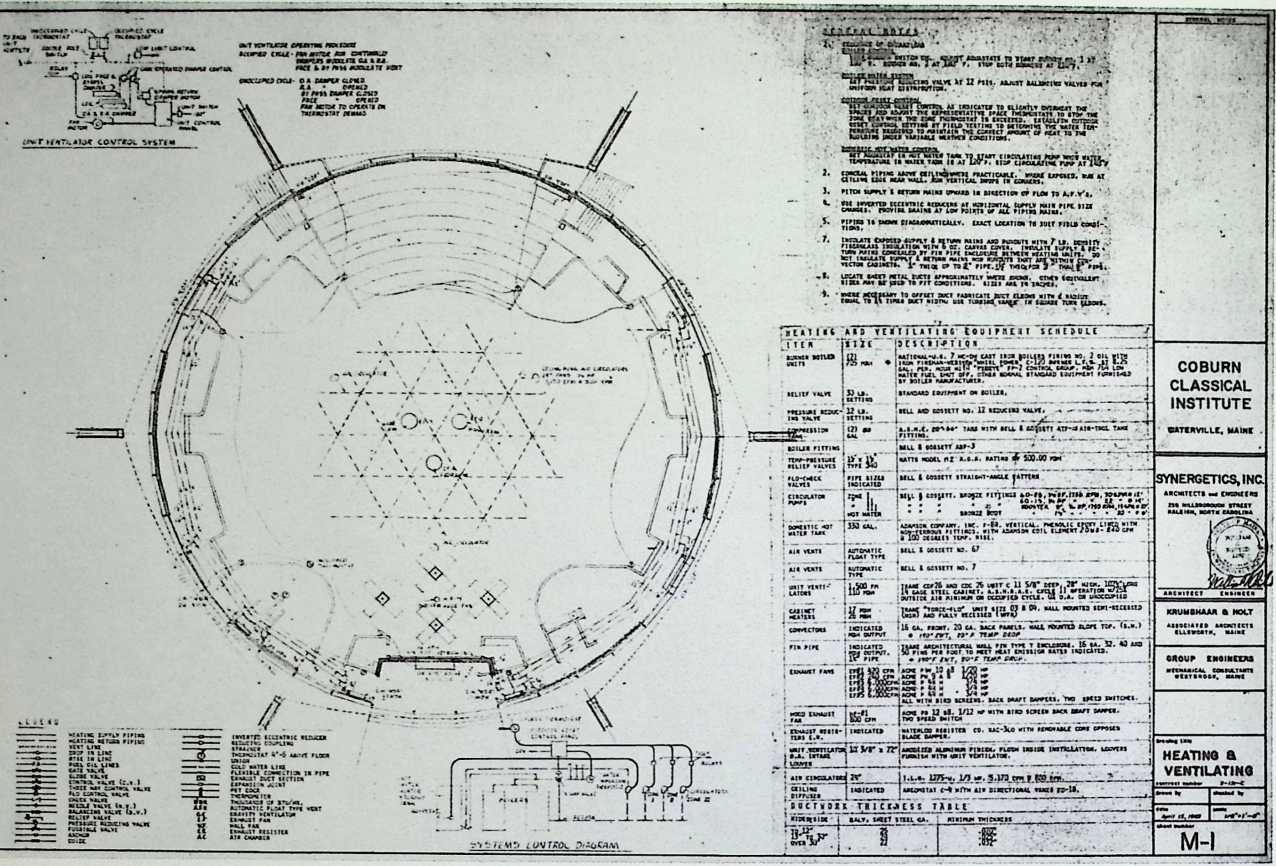
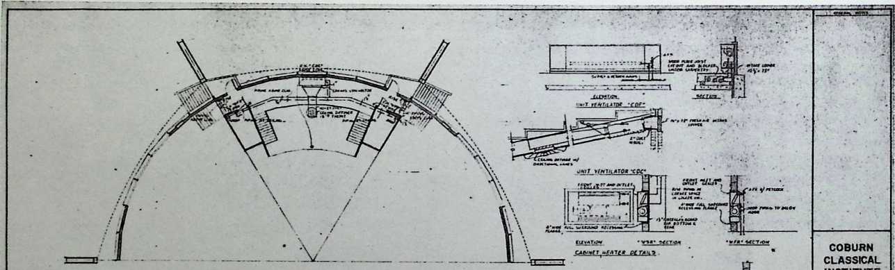
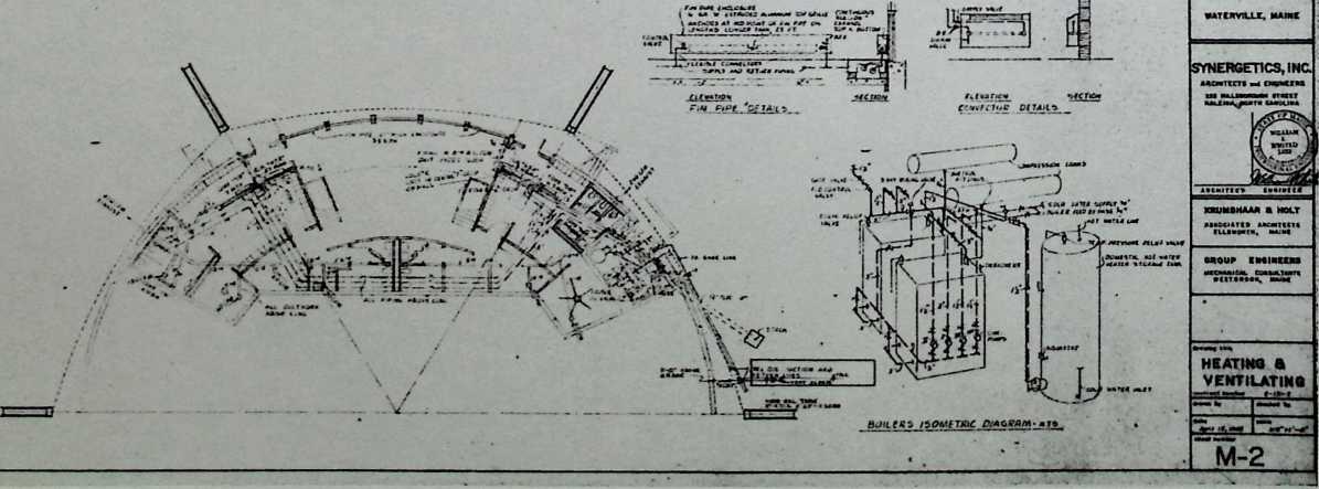
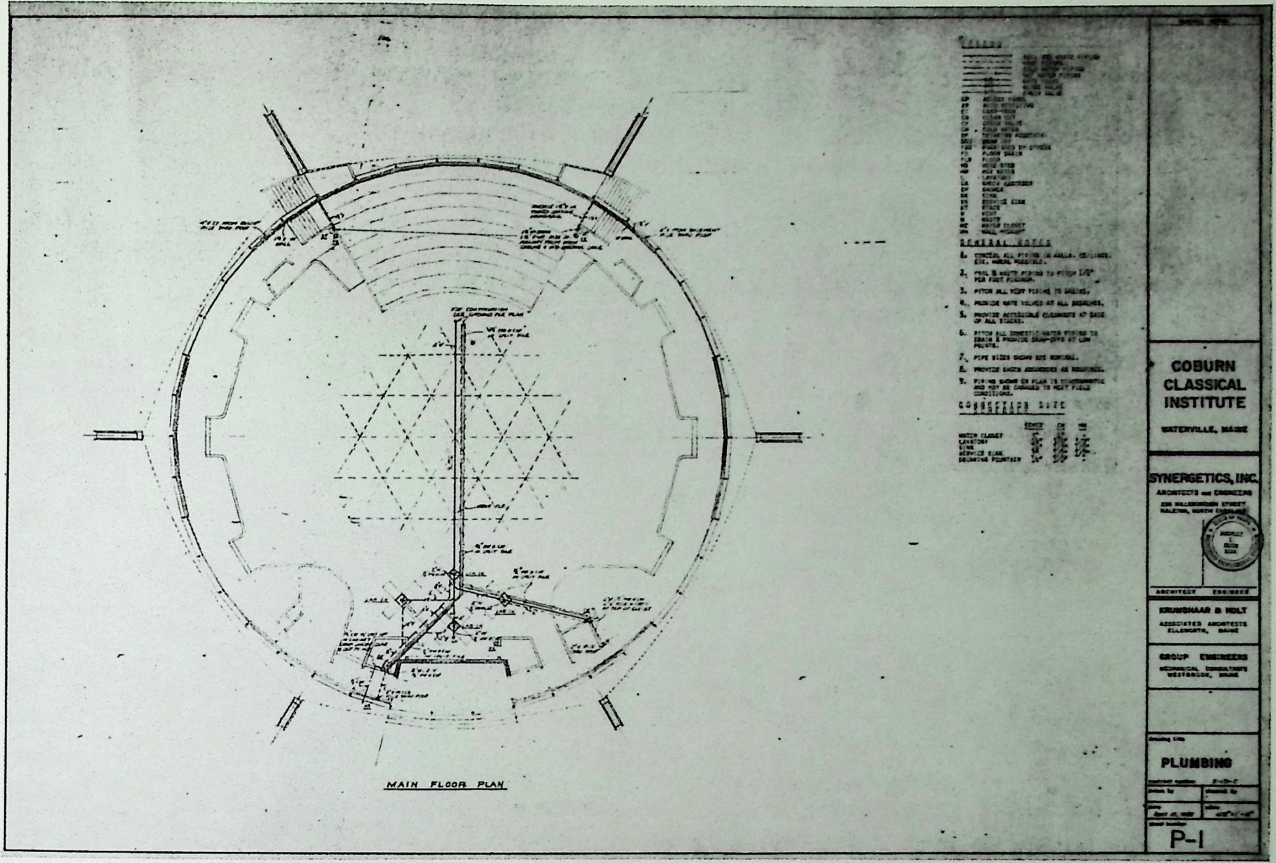
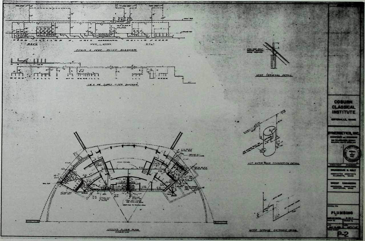
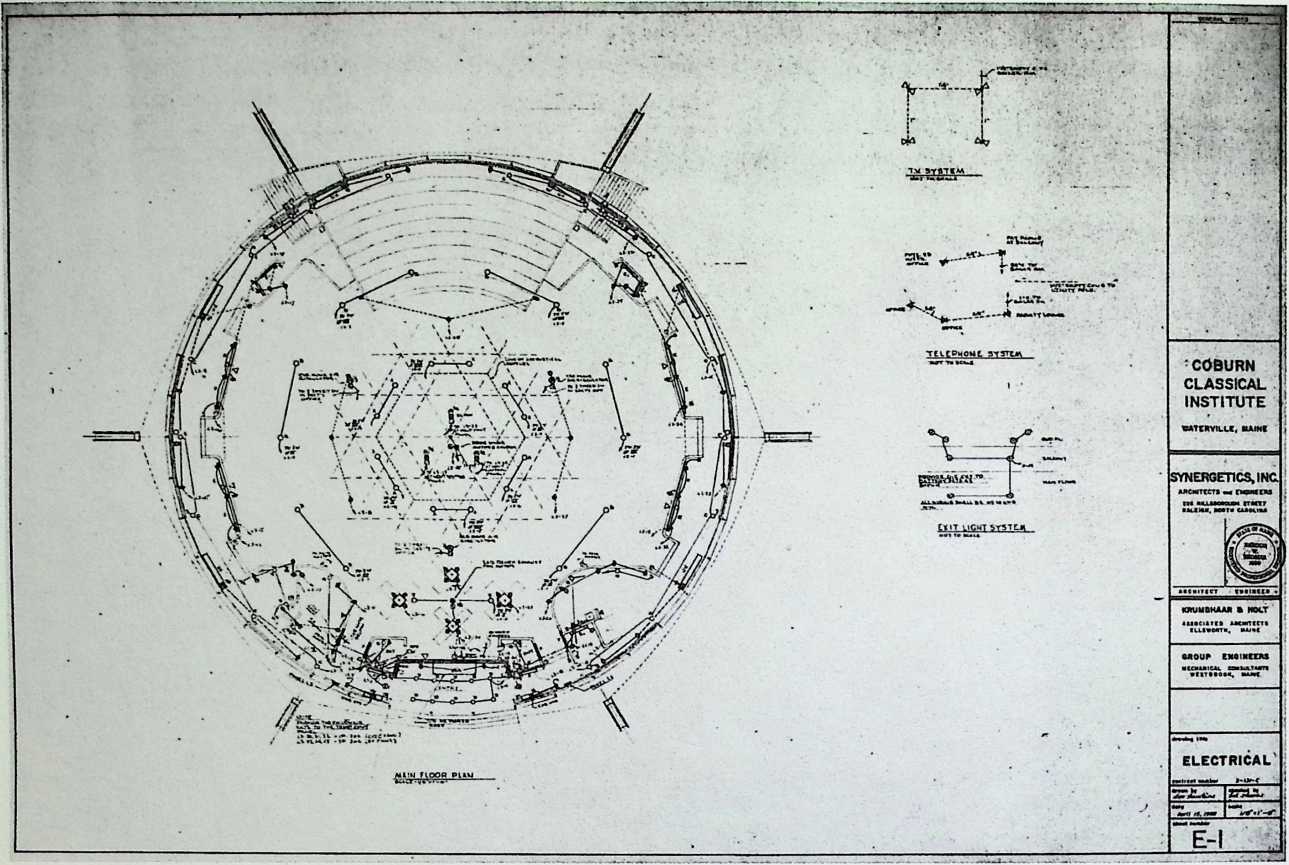
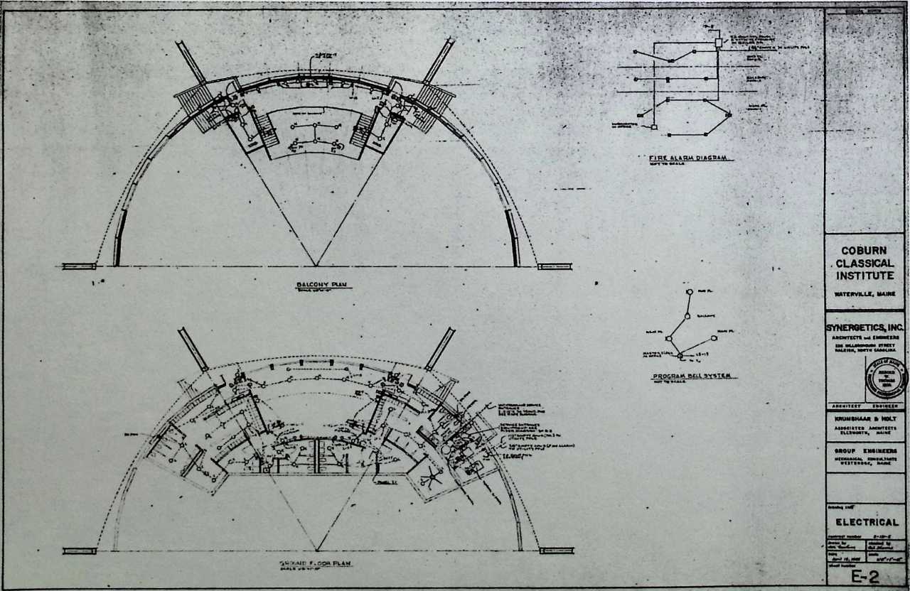
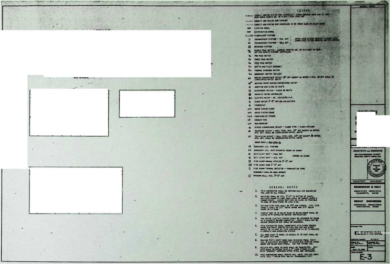
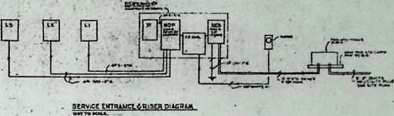
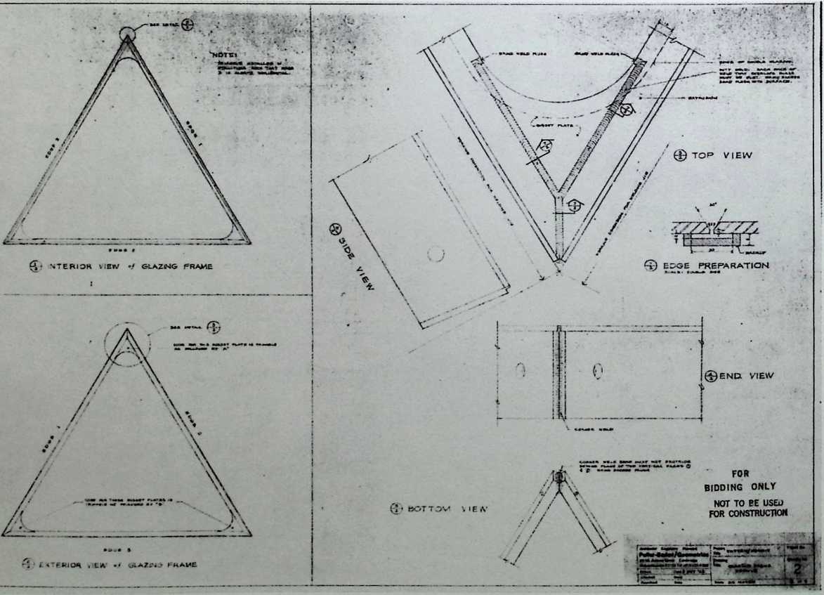
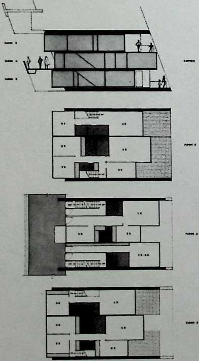
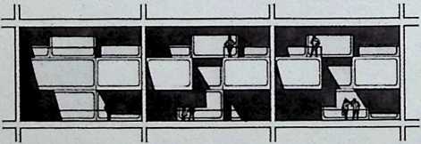
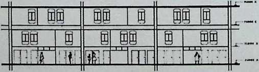
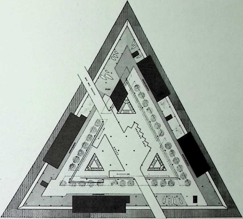
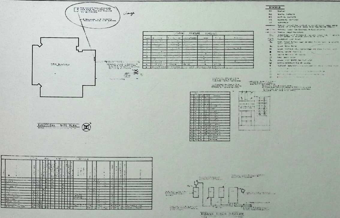
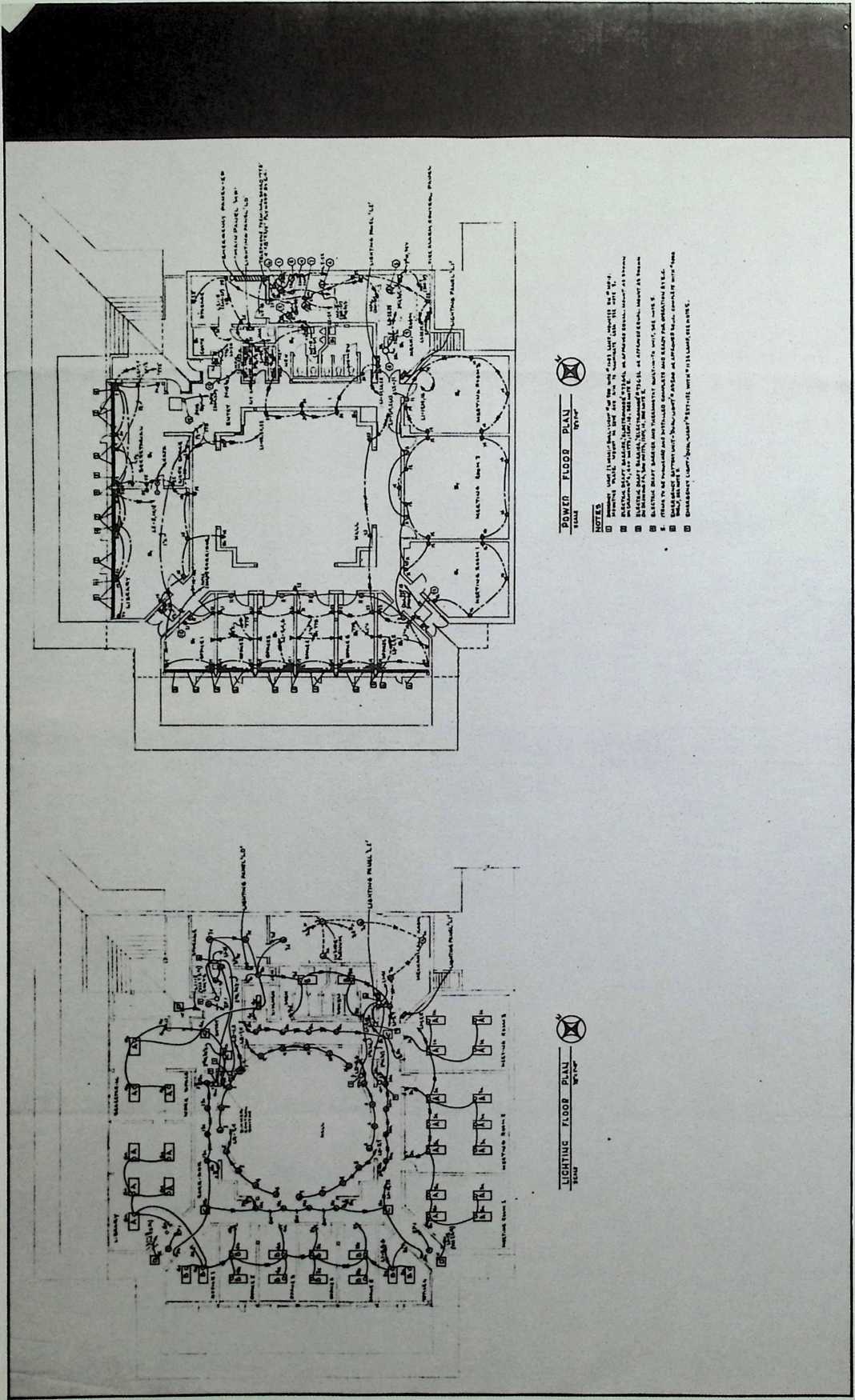
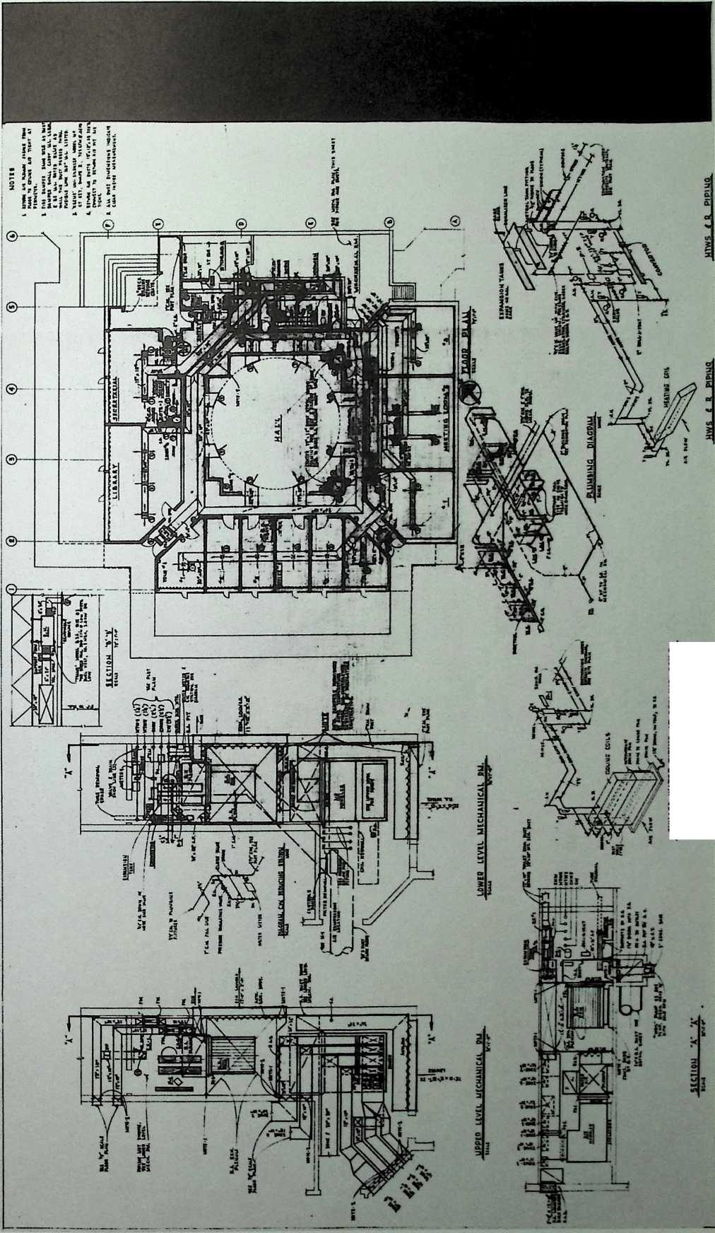
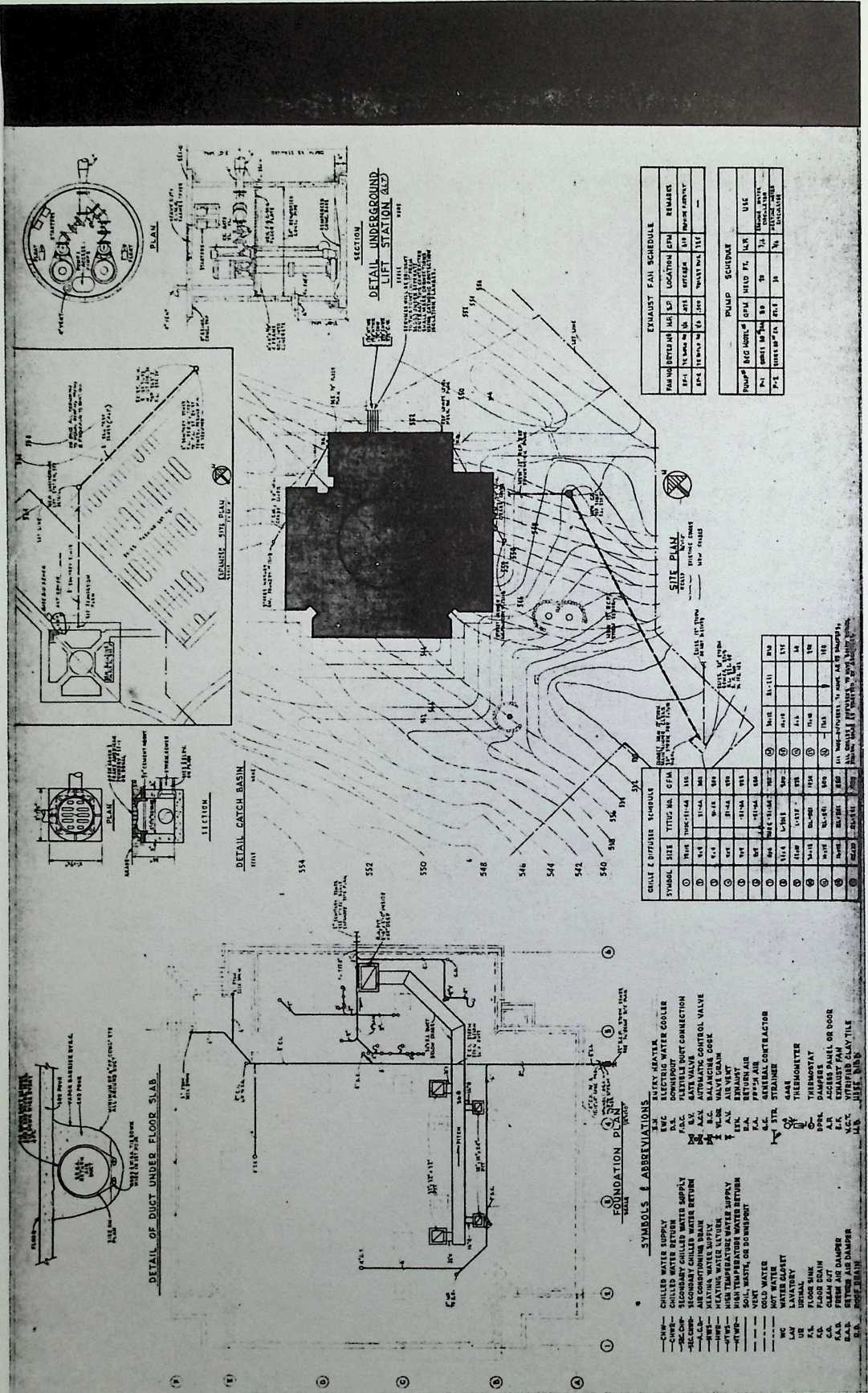
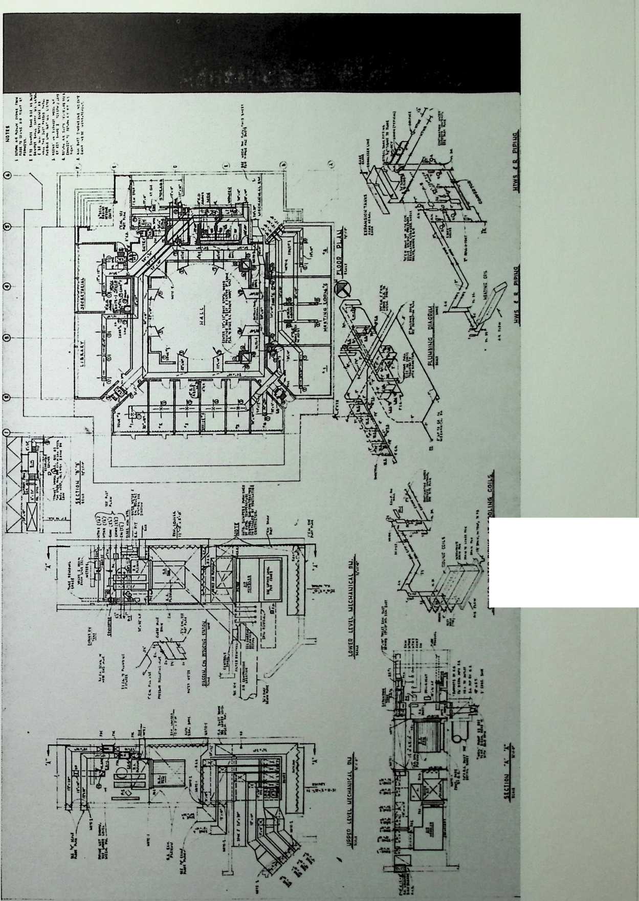
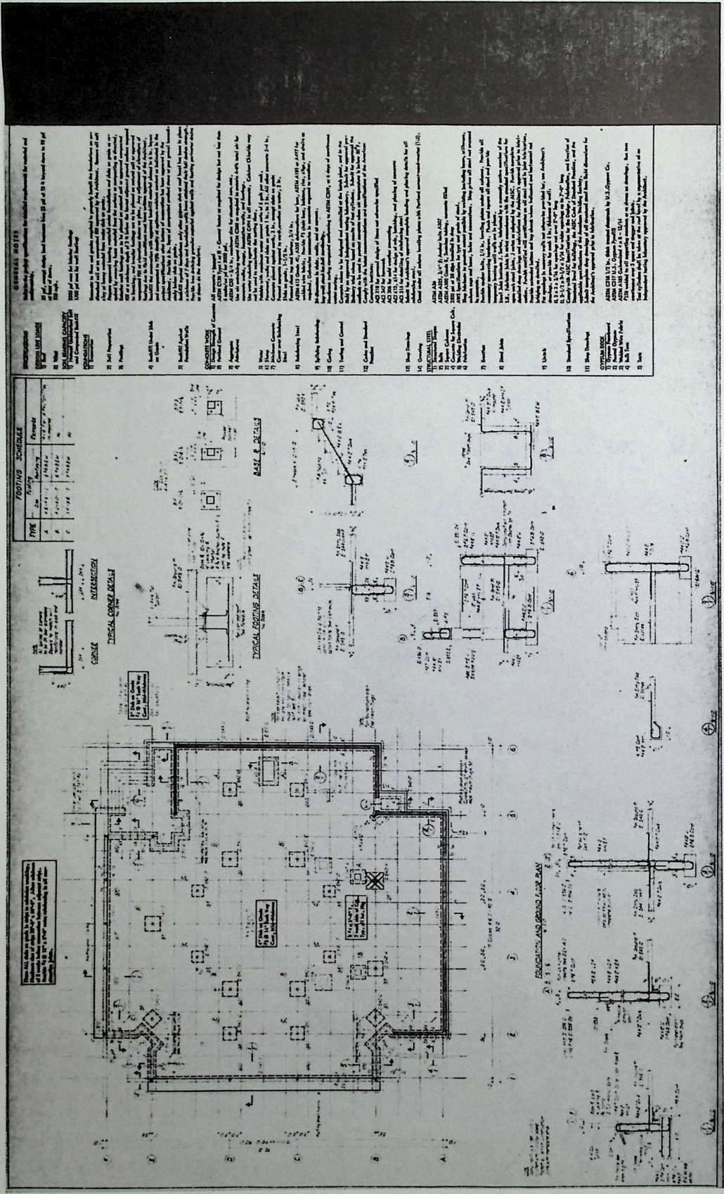
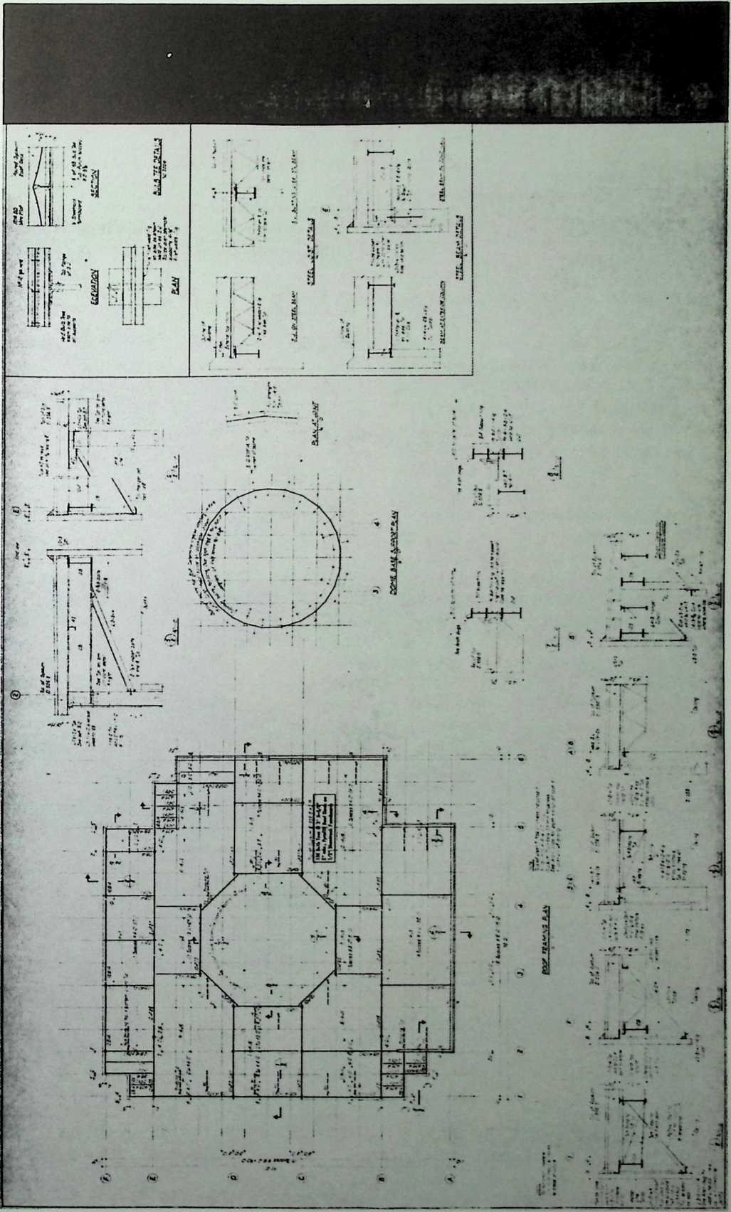
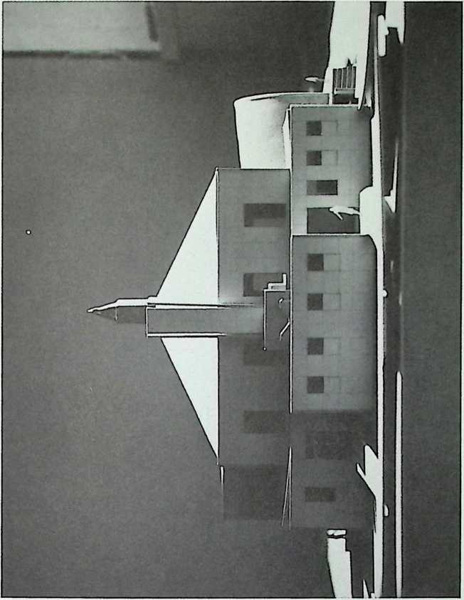
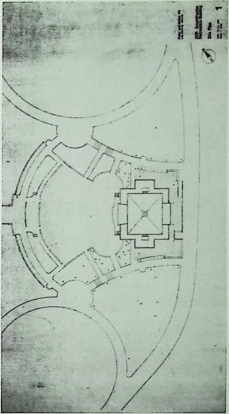
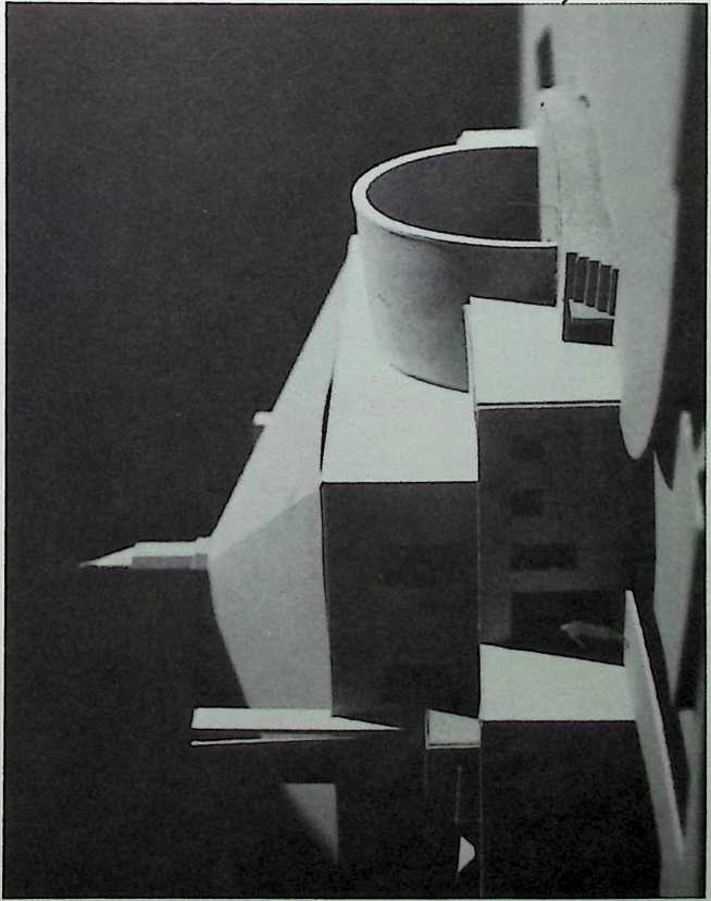
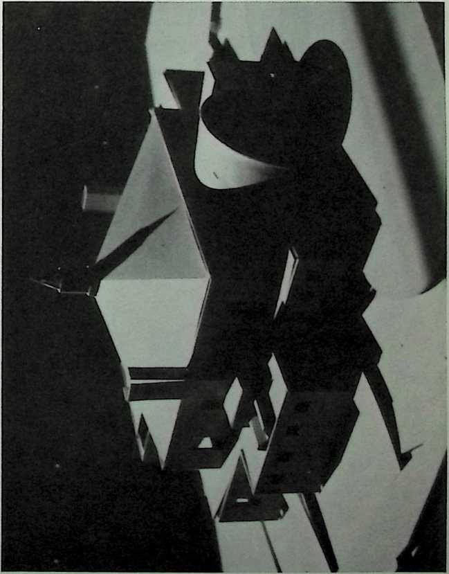
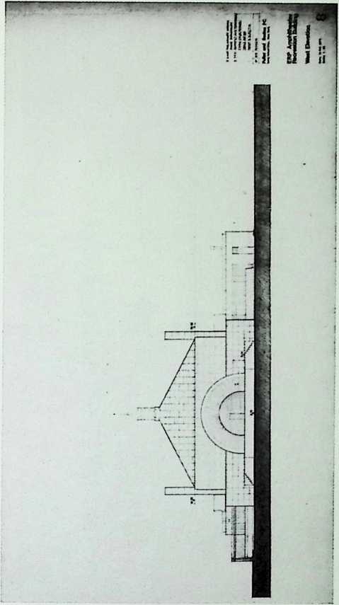
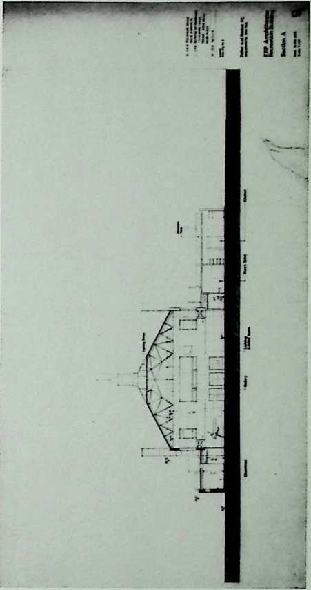
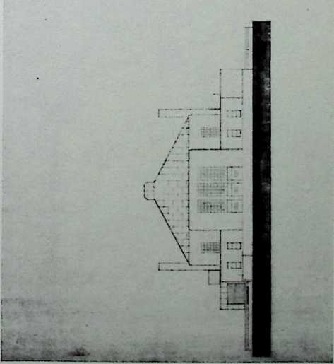
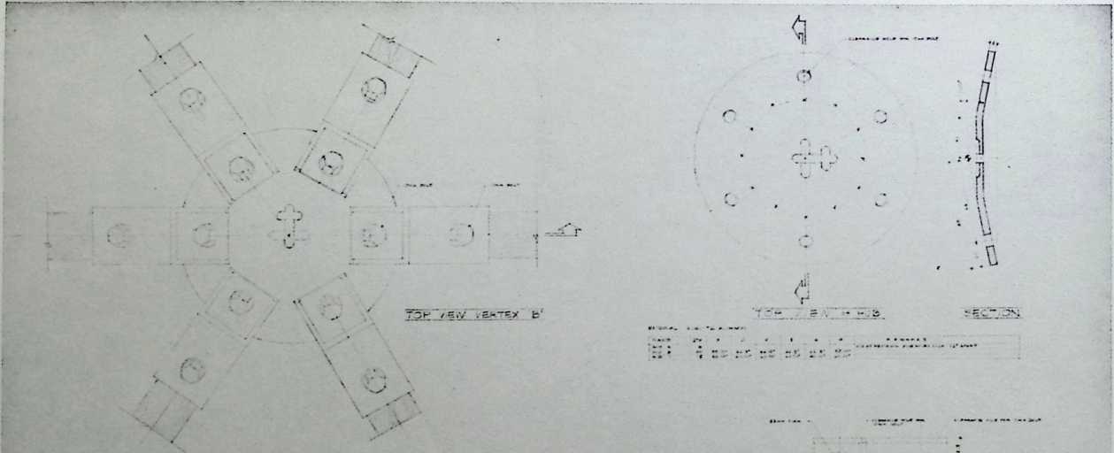
¶ Chapter 22 The Coburn Classical Institute, Waterville, Maine 1968
The Coburn Classical Institute was designed by Fuller with Krumbauer and Holt for the inclement weather of a northern college town. The seamless gypsum dome was designed to divert winter blasts, and the insulated interiors of this concert hall-planetarium were the most complex in Fuller’s oeuvre. It would have been one of the first of his domes to be constructed of poured gypsum and steel I beams.
COBURN CLASSICAL INSTITUTE
WATERVILLE, MAINE
SYNERGETICS, INC.
![]()
![]()
KRUMS HA AR A HOLT
GROUP ENGINEERS
MOMMCAL C3—LtTAMTl
«tari*09«. bam
DRAW
ARCHITECTURAL
1.
• SITE PLAN
2.
• MAIN FLOOR PLAN
3.
• BALCORY a GROUND FLOOR PLAN
4.
• BUILDING ELEVATIONS
5.
■ BUILDING SECTIONS
S • 1/2 MAIN FLOOR PLAN (NORTH)
7 • 1/2 MAIN FLOOR PLAN (SOUTH)
• • BALCONY PLAN
S • GROUND FLOOR PLAN
10.
• WALL SECTIONS A DETAILS
11.
• DETAILS
ING I
STRUCTURAL
12.
• FOUNDATION PLAN B DETAILS I2A* CONCRETE REINFORCING DETAILS IS • GROUND FLOOR B BALCONY STRUCTURAL PLANS B DETAILS
14.
* DOME PLAN & DECKING DETAILS
15.
• DOME ERECTION DETAILS
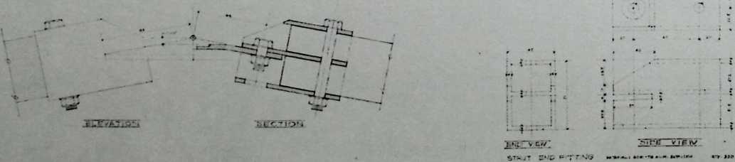
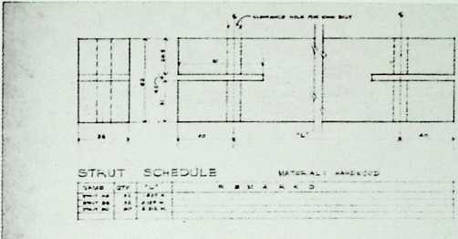
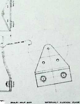
IB • DOME FRAME MEMBERS
IT * DOME FRAME VERTEX PLATES
IS * DOME FRAME FITTINGS IB • SPECIAL EQUIPMENT
N D E X t
MECHANICAL
Ml - KEATING a VENTILATING M-2 * HEATING A VENTILATING ‘‘PI* PLUMBING
P-2 - PLUMBING E-l • ELECTRICAL E-2 - ELECTRICAL E» - ELECTRICAL
![]()
I No I1 IUI t.
ELECTRICAL
M»iH DiSraiUTICM PANEL C«TT»t *4«W«M A auwa M-O
|
||||
err |
*104 |
▼ a > |
•C41 |
|
4 |
11 •‘‘L Lt »-»a« |
■ 1 * » |
IHH |
|
COBURN
CLASSICAL
INSTITUTE
[SYNERGETICS, INC
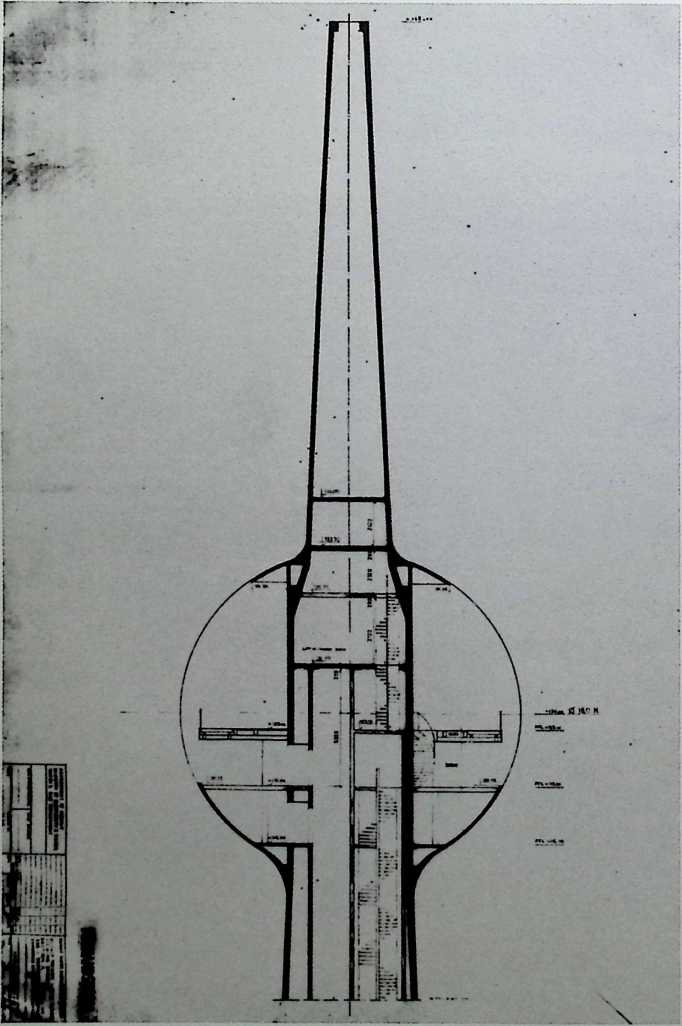
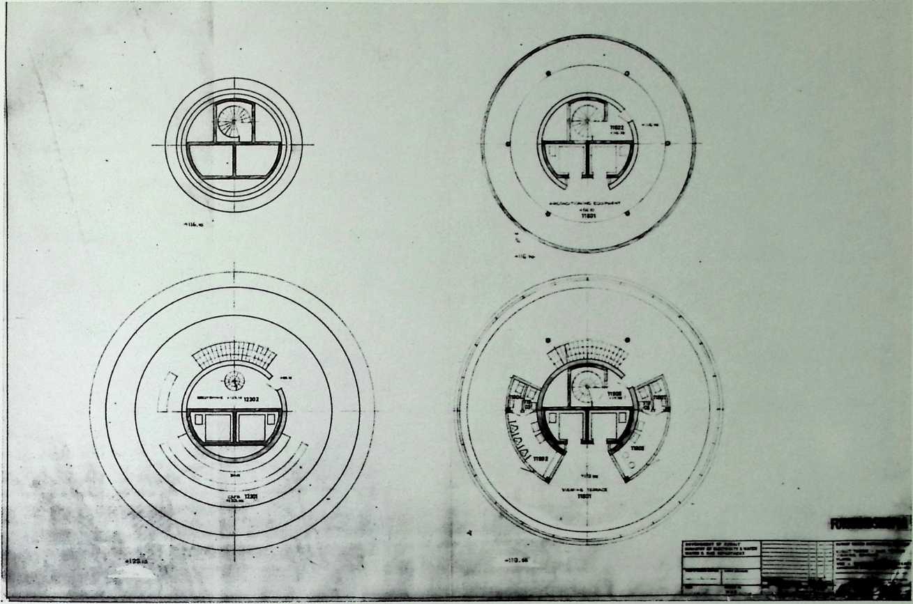
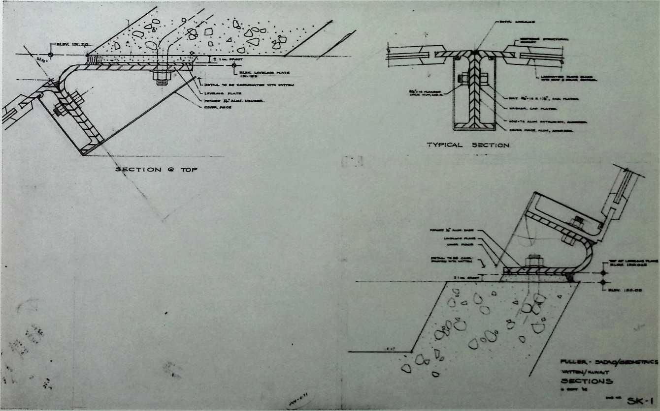
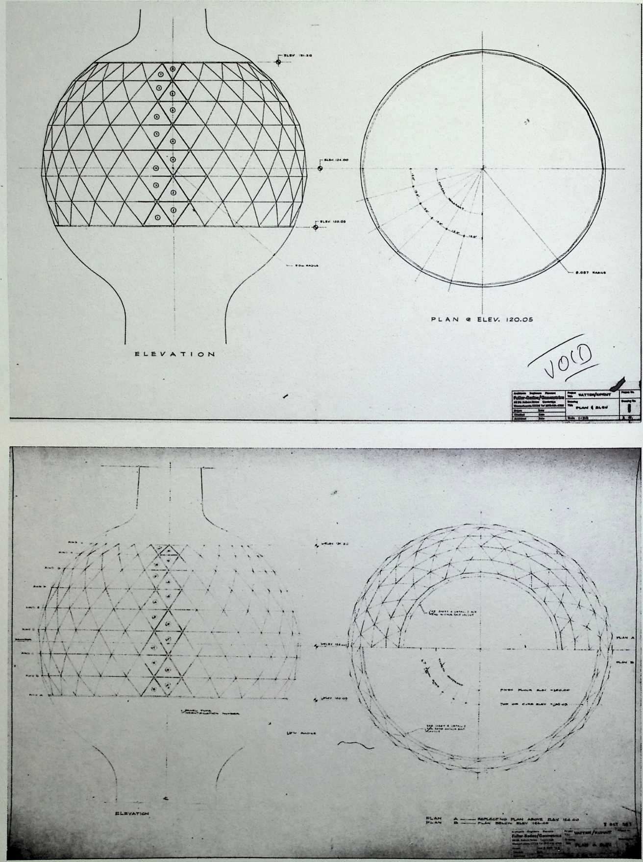
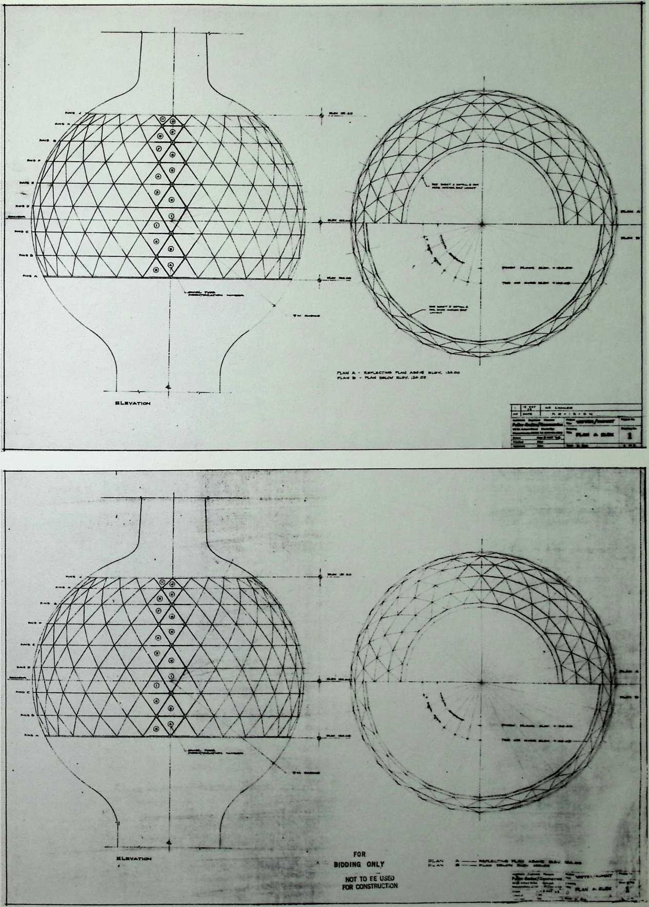
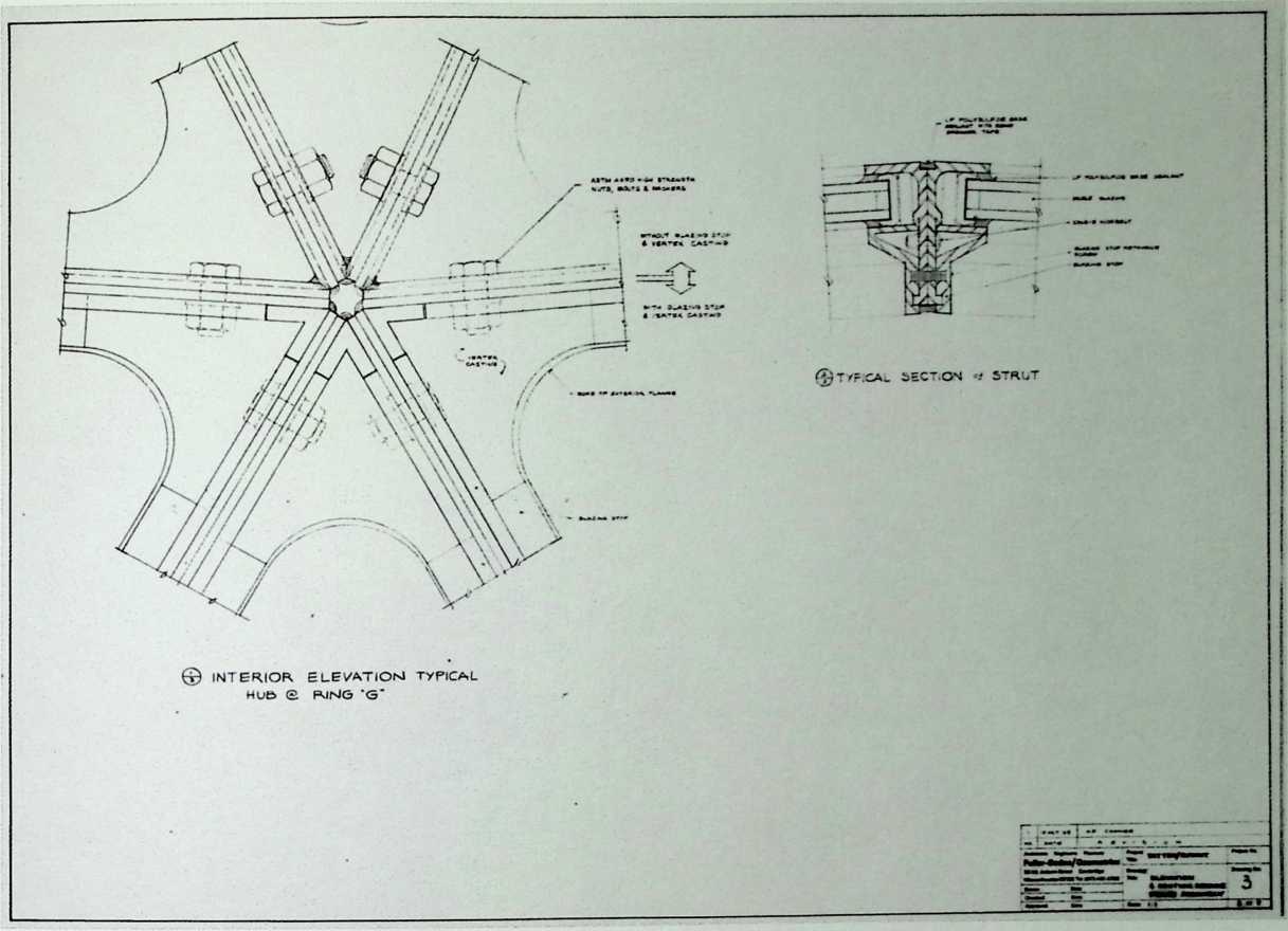
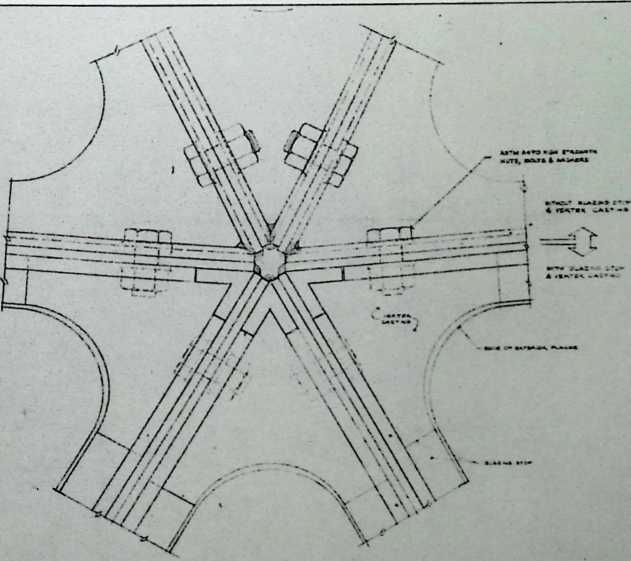
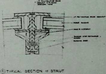
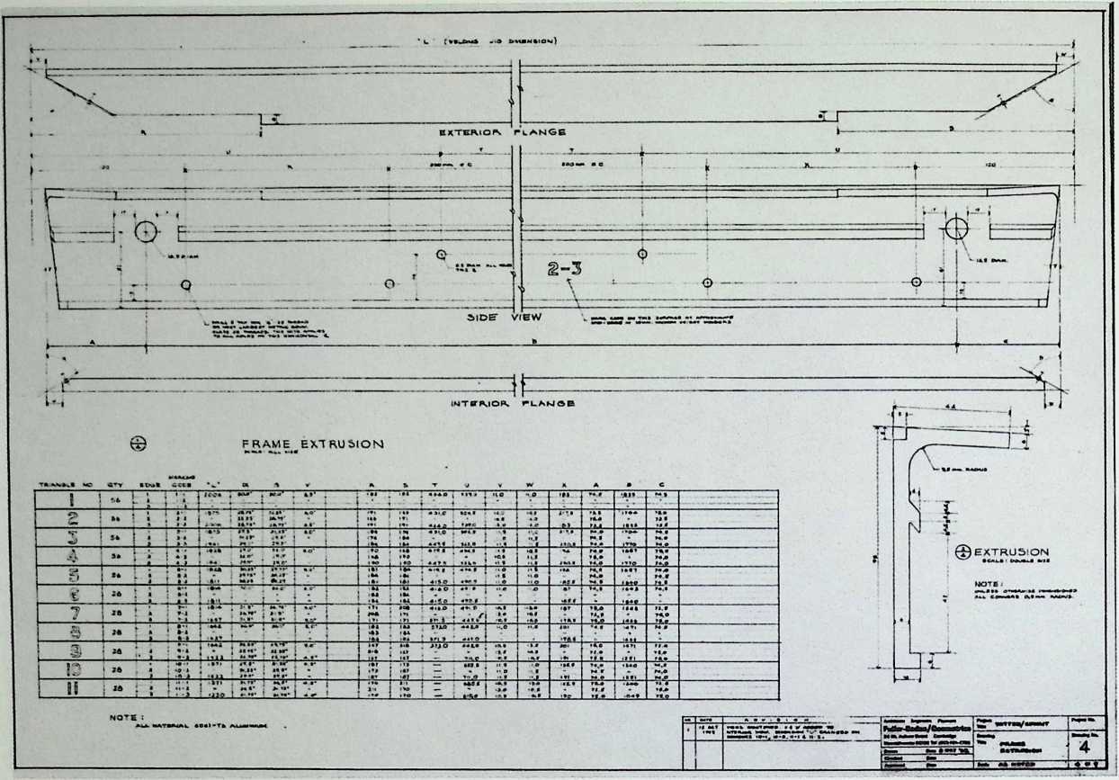
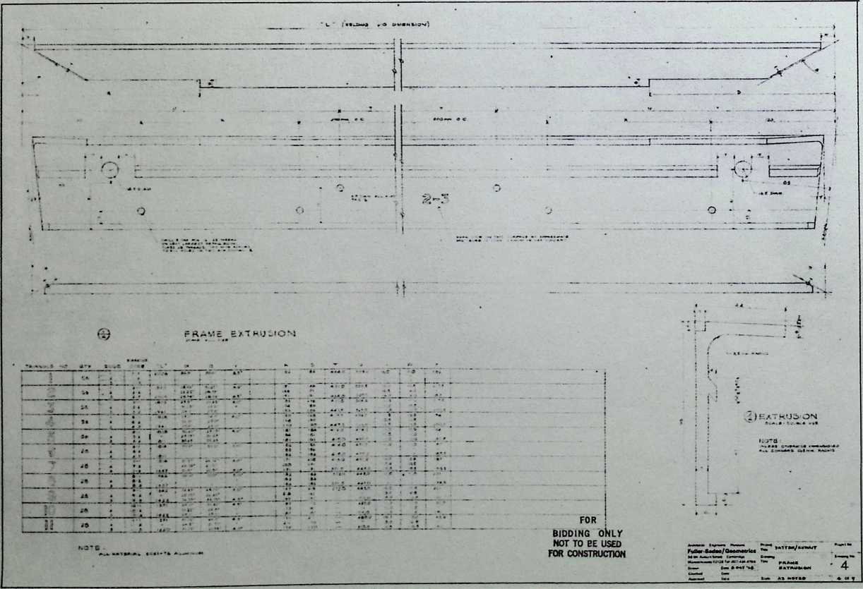
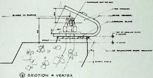
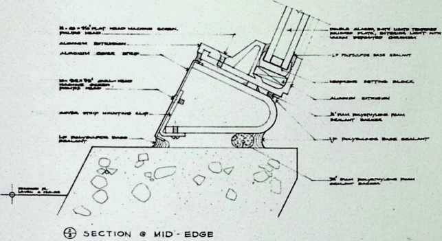
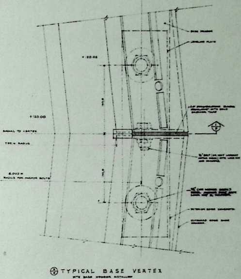
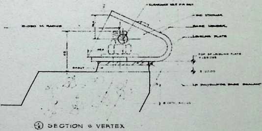
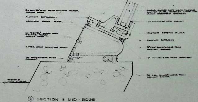
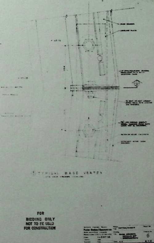
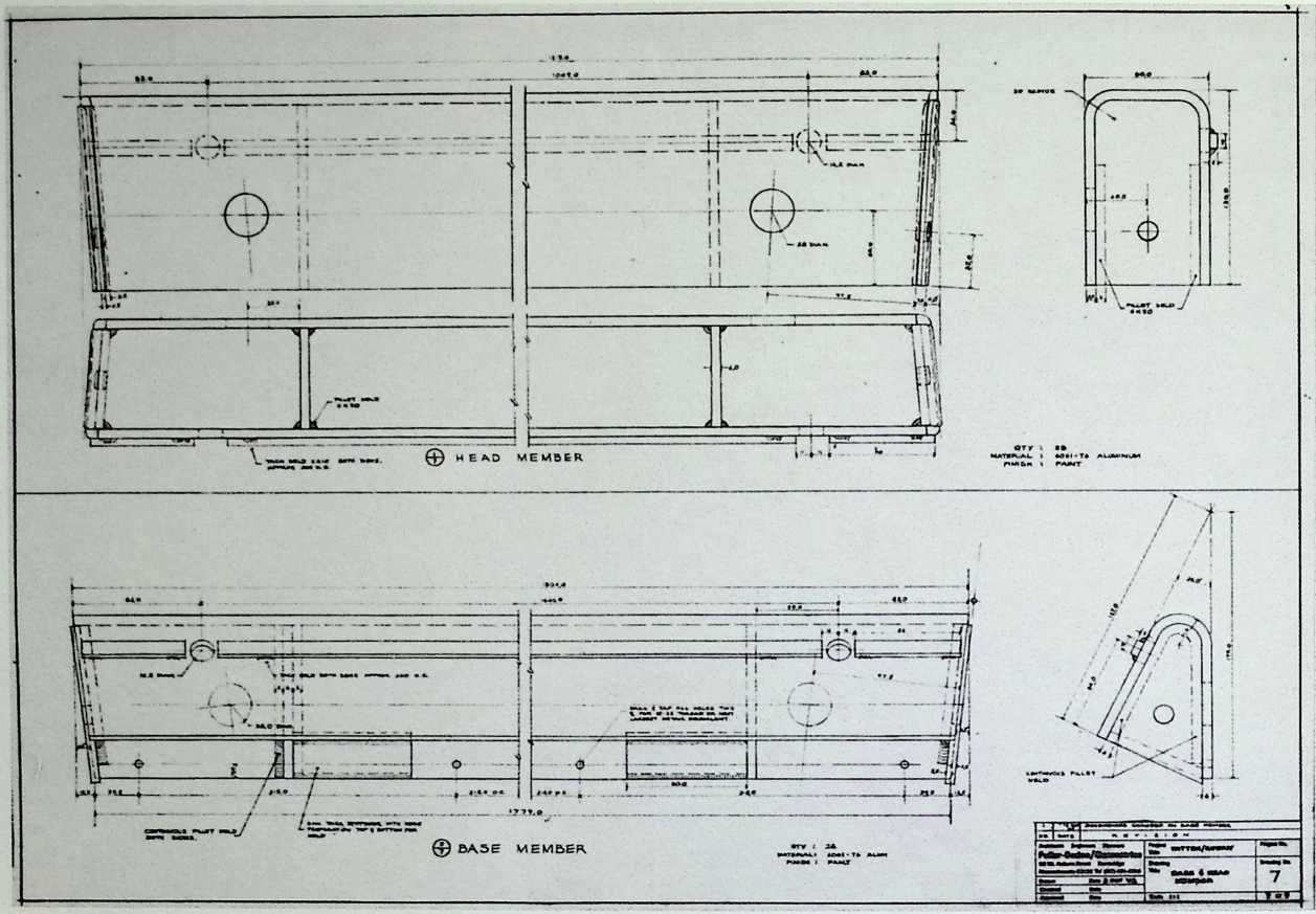
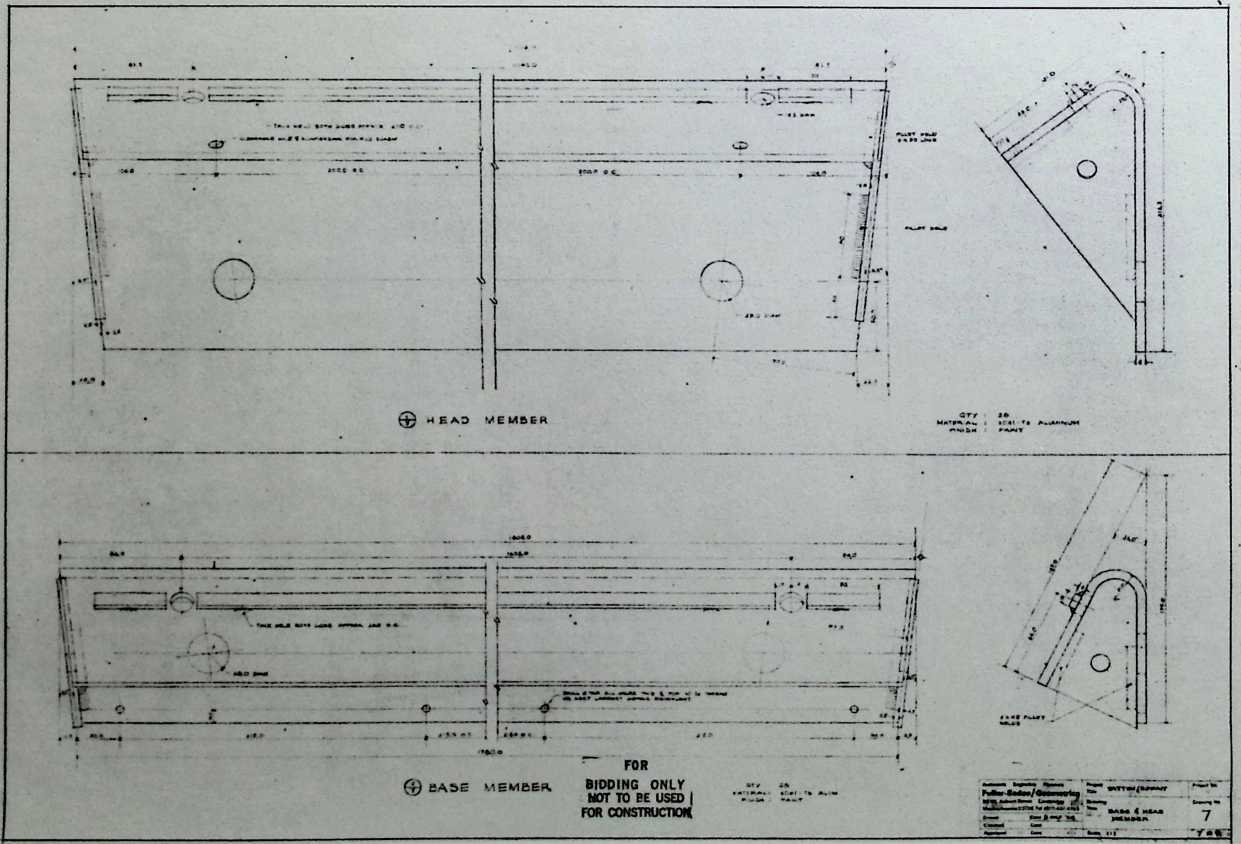
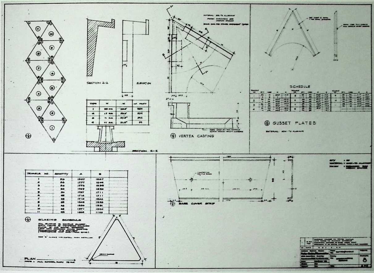
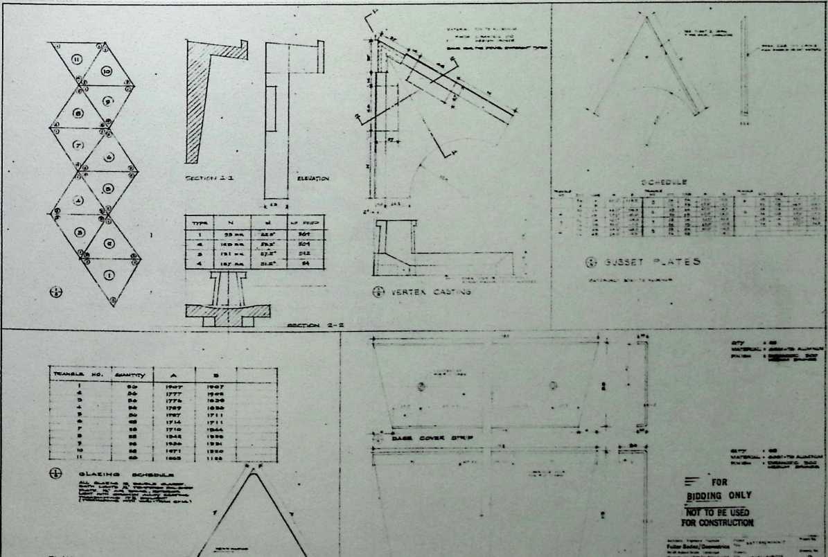
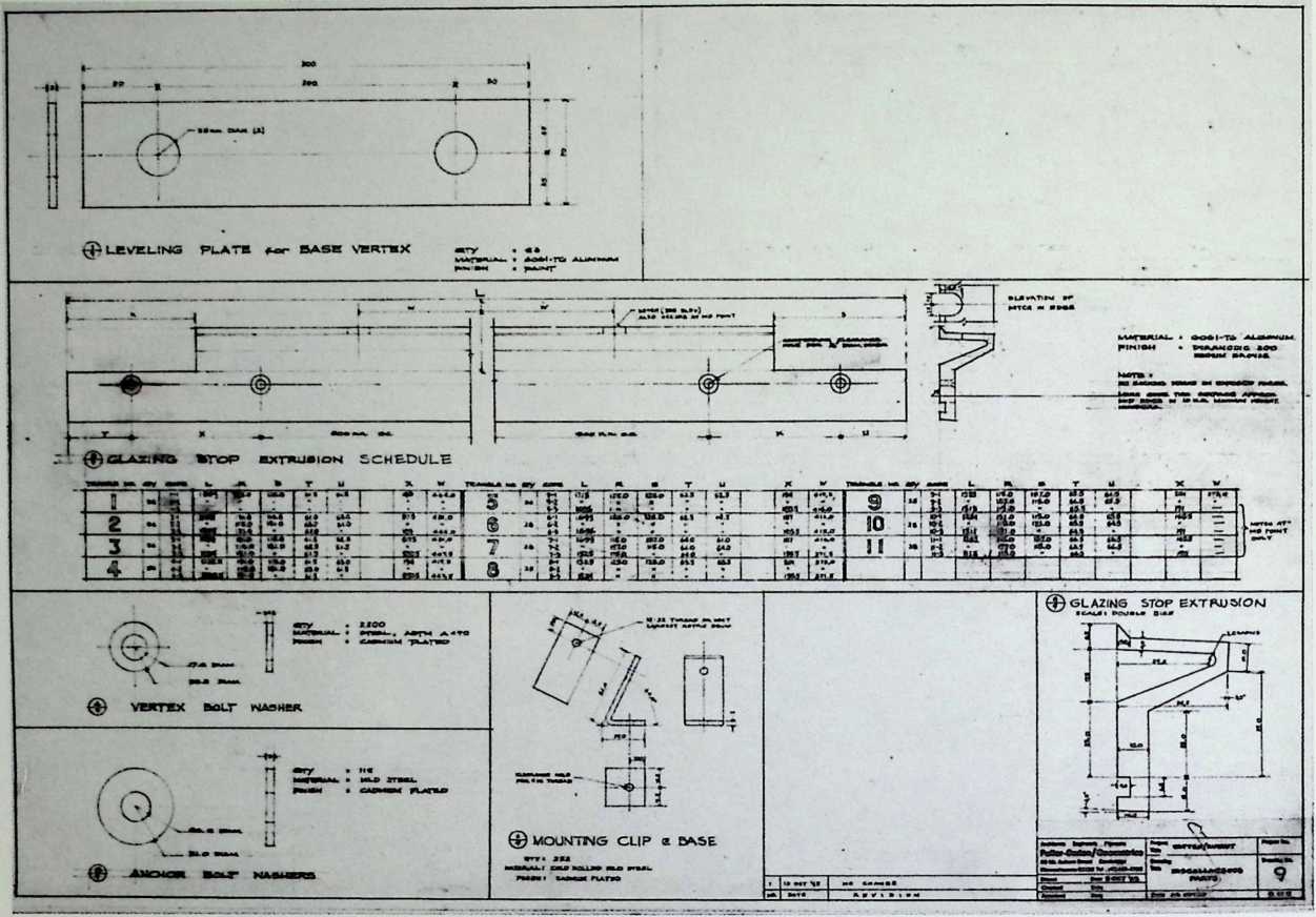
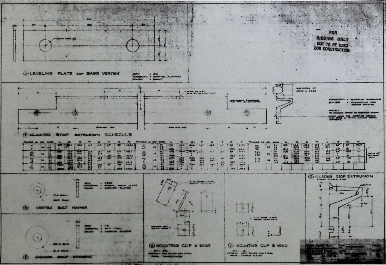
Main Observation Tower, Government of Kuwait, Ministry of Electricity and Water
Fuller & Sadao with
Geometries, Inc., 1968
This observation tower combines the volumes of the cone and sphere. Designed by Fuller for the government of Kuwait, this irrigation observation tower was constructed by a Swedish firm. The center of the dome is a glazed geodesic structure that provides a 360° view of the site.
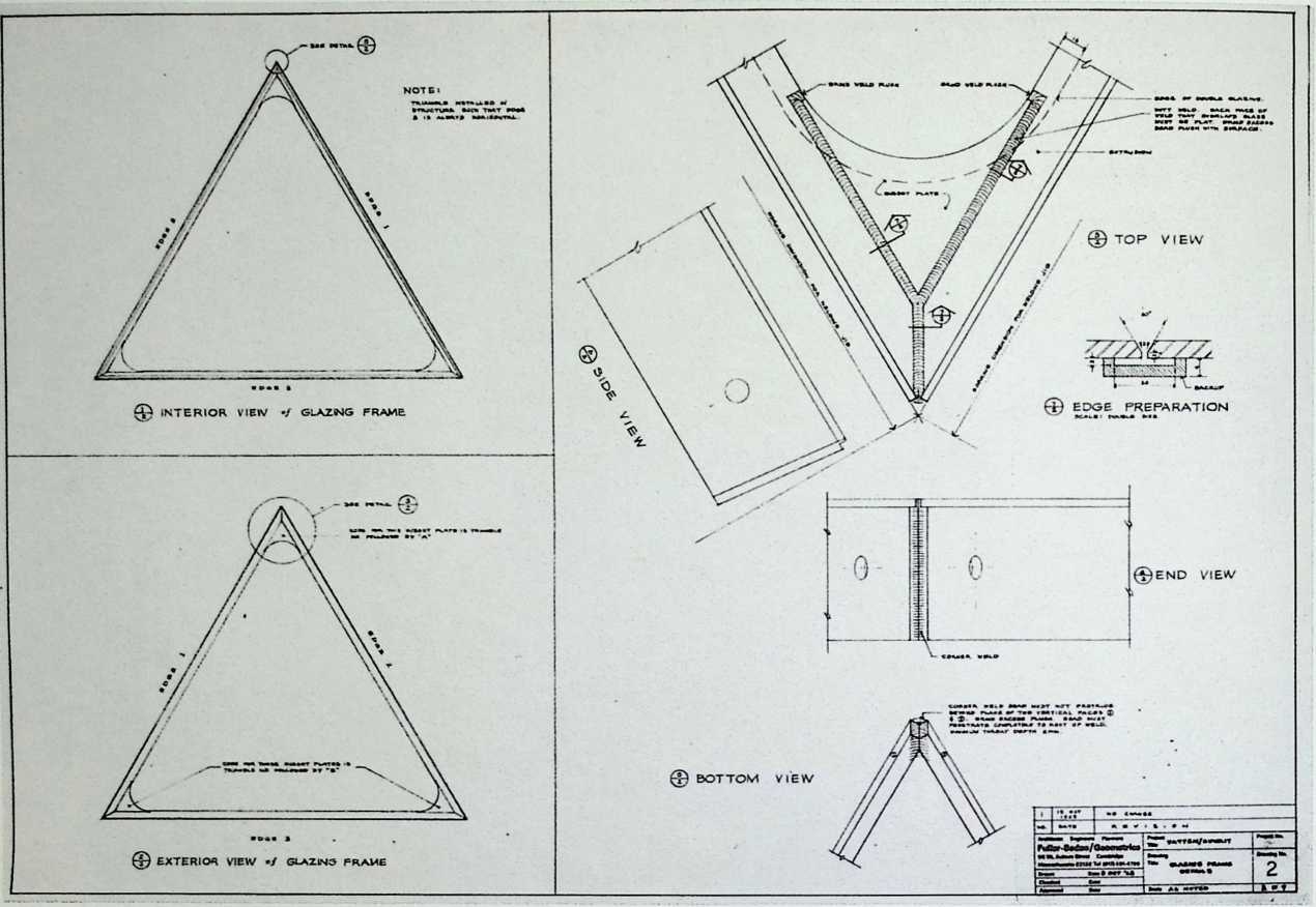
© INTERIOR ELE/VTiOM TyP»CA»L
HUt> £. RING *G*
FOR
BIDDING ONLY
NOT TO FE UScJ
FOR CONSTRUCTOR
![]()
![]()
HL.
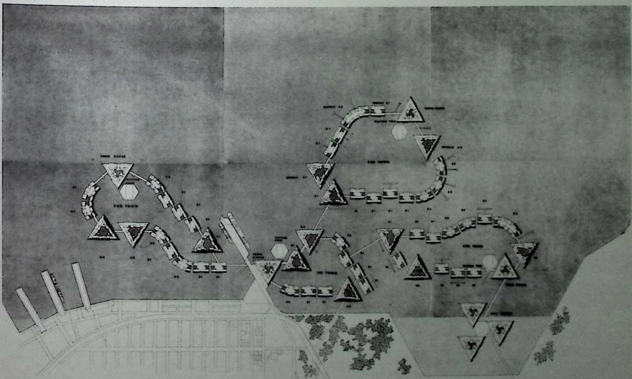
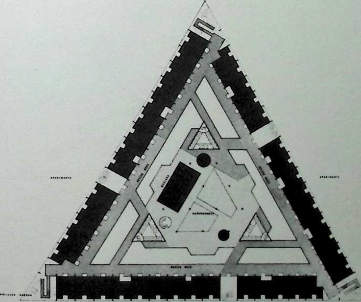
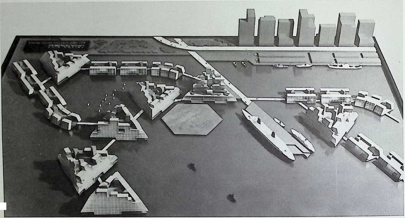
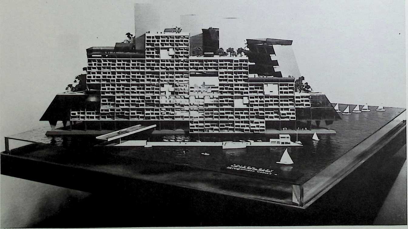
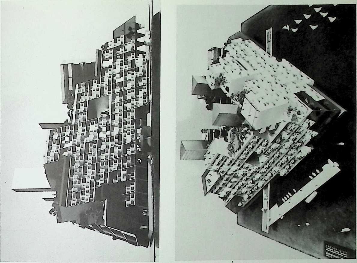
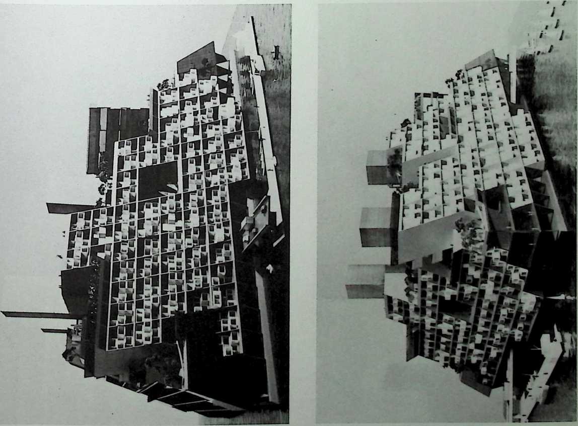
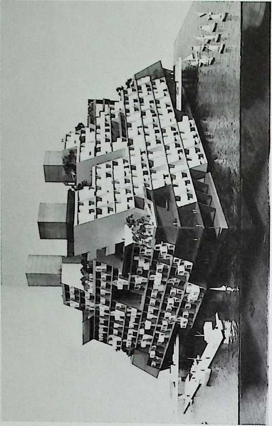
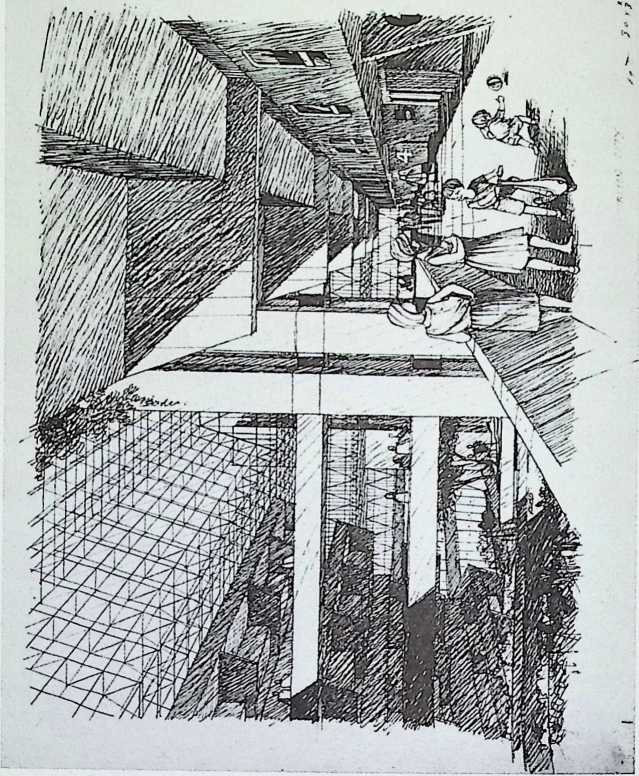
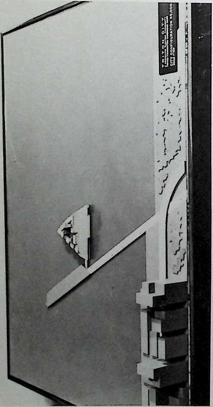
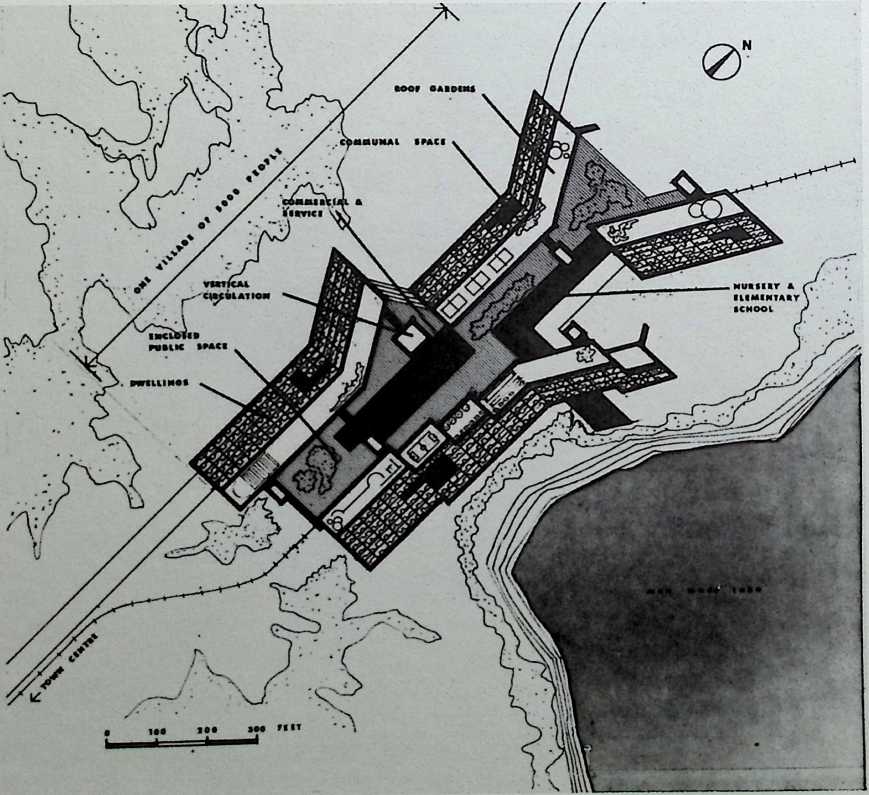
Triton City, Triton Foundation
Fuller & Sadao, 1968
Fuller & Sadao founded the Triton Foundation during the late sixties. They designed this self-sufficient concrete structure for the U.S. Department of Housing and Urban Development with other members of the foundation in 1968. The tetrahedral housing cluster was intended to be floated offshore. The ‘‘megastructure’’ of this city would be fully equipped to house 5,000 people, who would have made use of stores, schools, and other public spaces designed for the uppermost levels.
TRITON CITY
A PROTOTYPE FLOATING COMMUNITY Mali « r •
MODULE ’A’ SECTION
EXTERIOR ELEVATION
INTERIOR ELEVATION
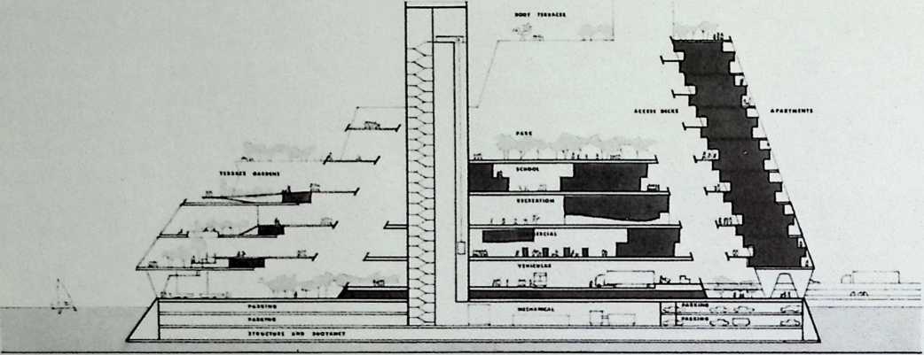
TRITON CITY MODULE ‘A’
A PROTOTYPE FLOATING COMMUNITY VEHICLE LEVEL
► o
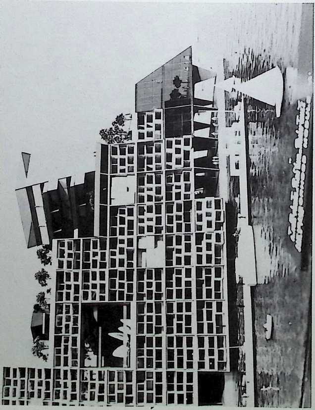
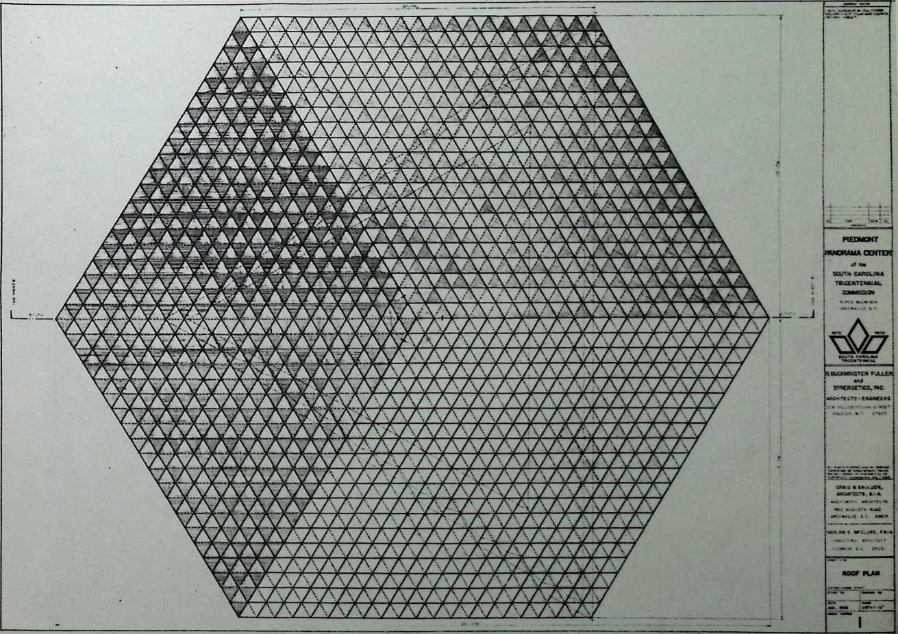
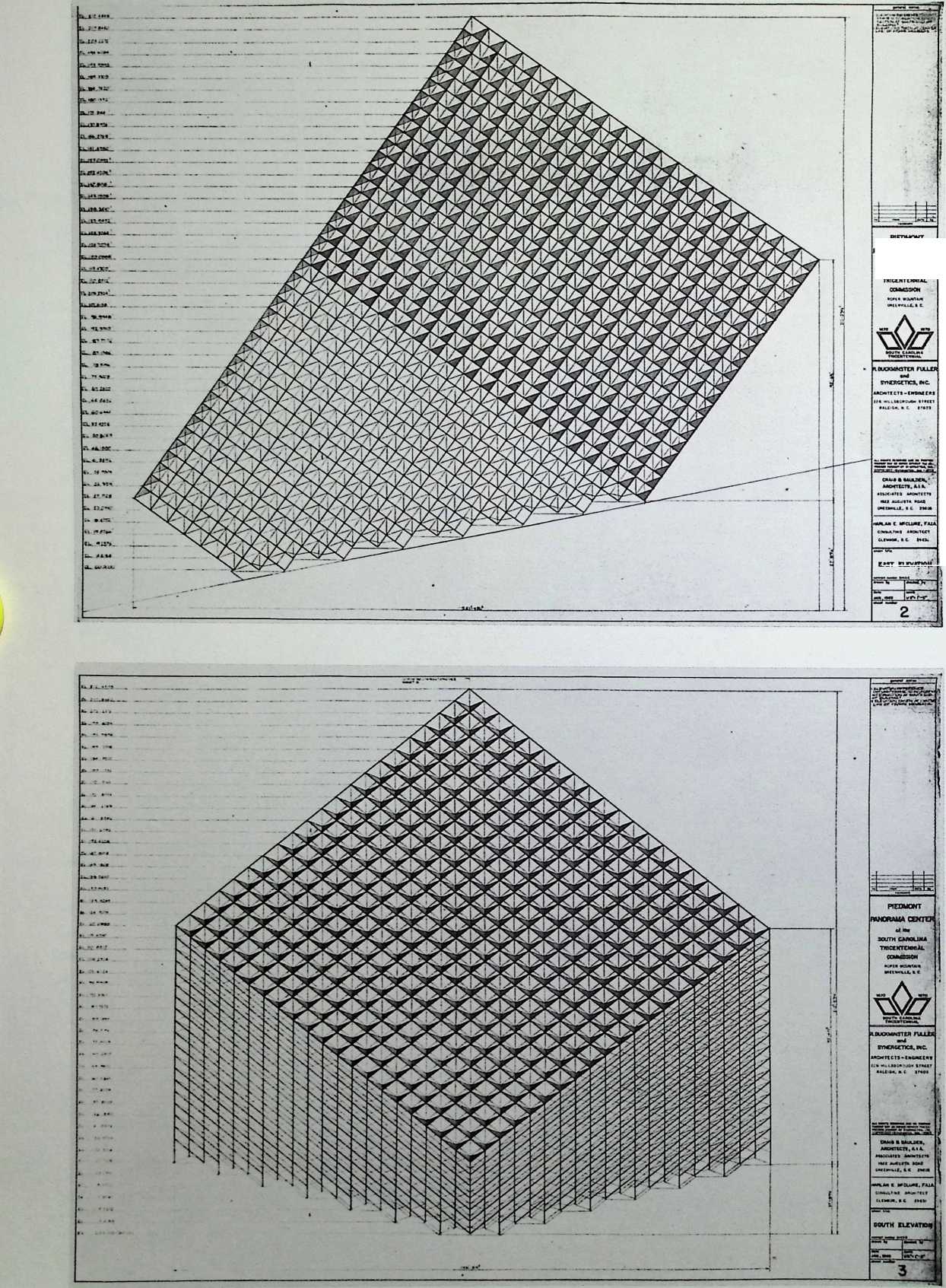
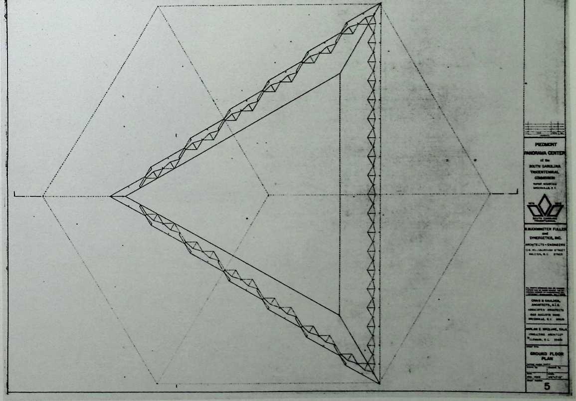
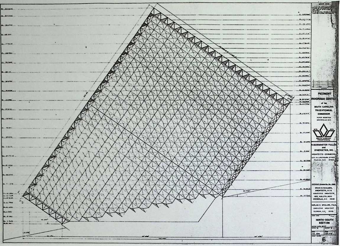
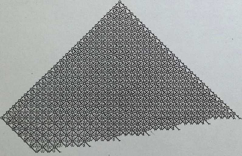
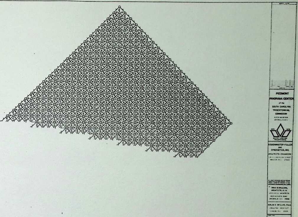
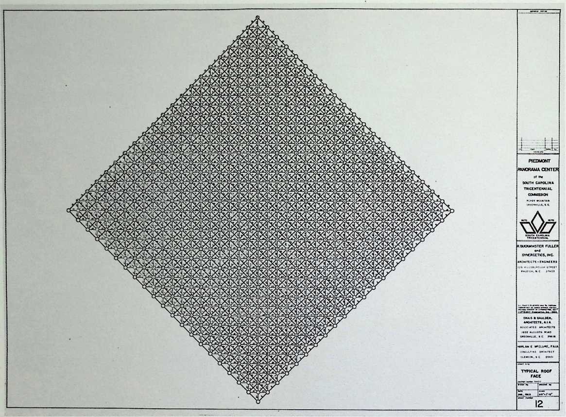
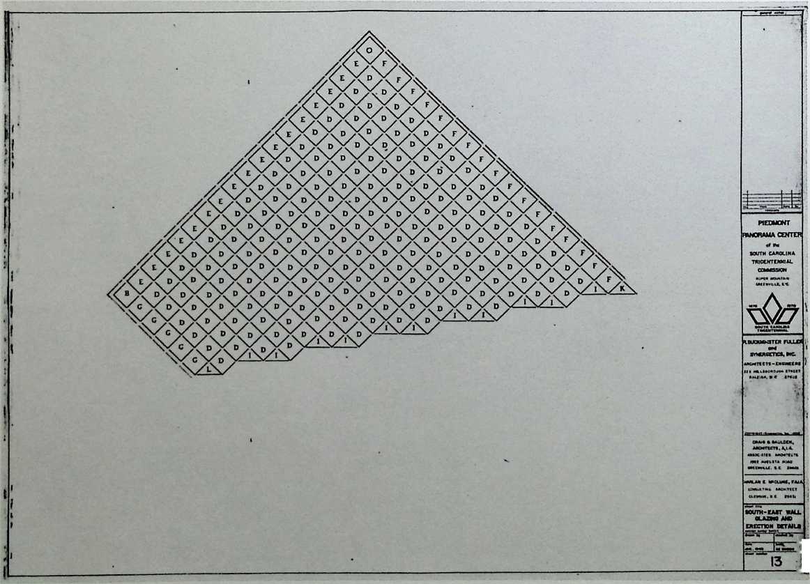
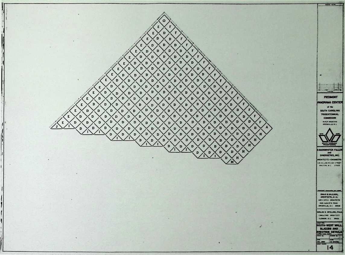
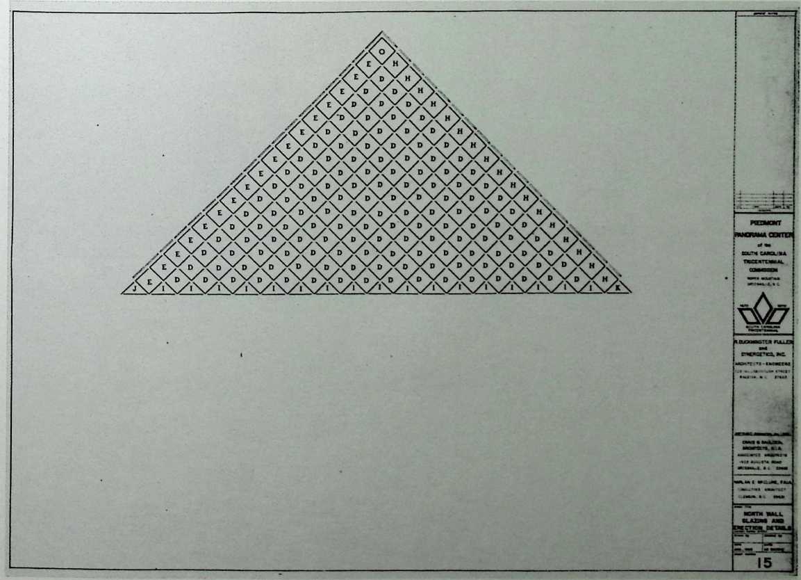
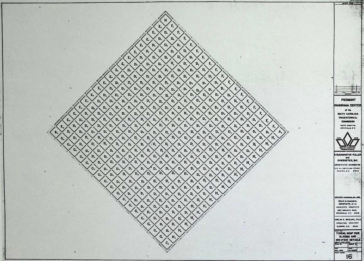
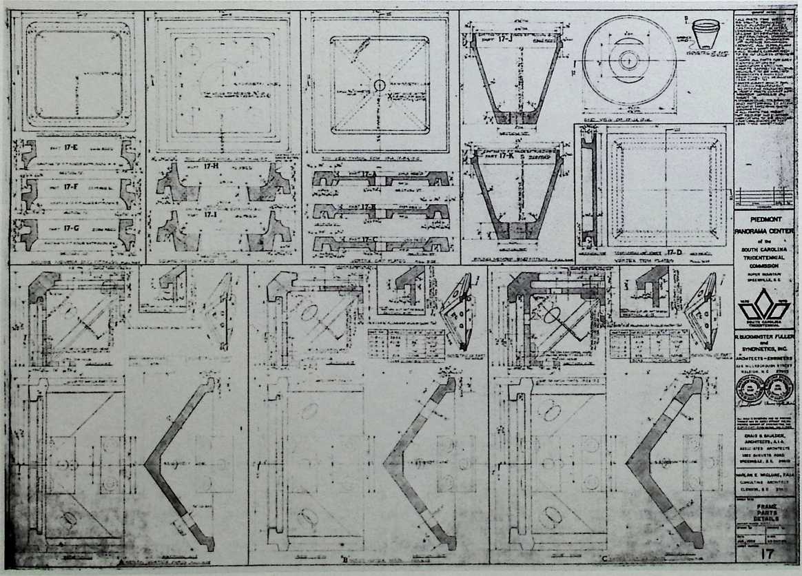
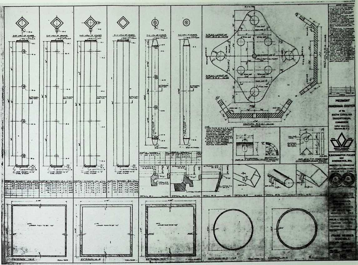
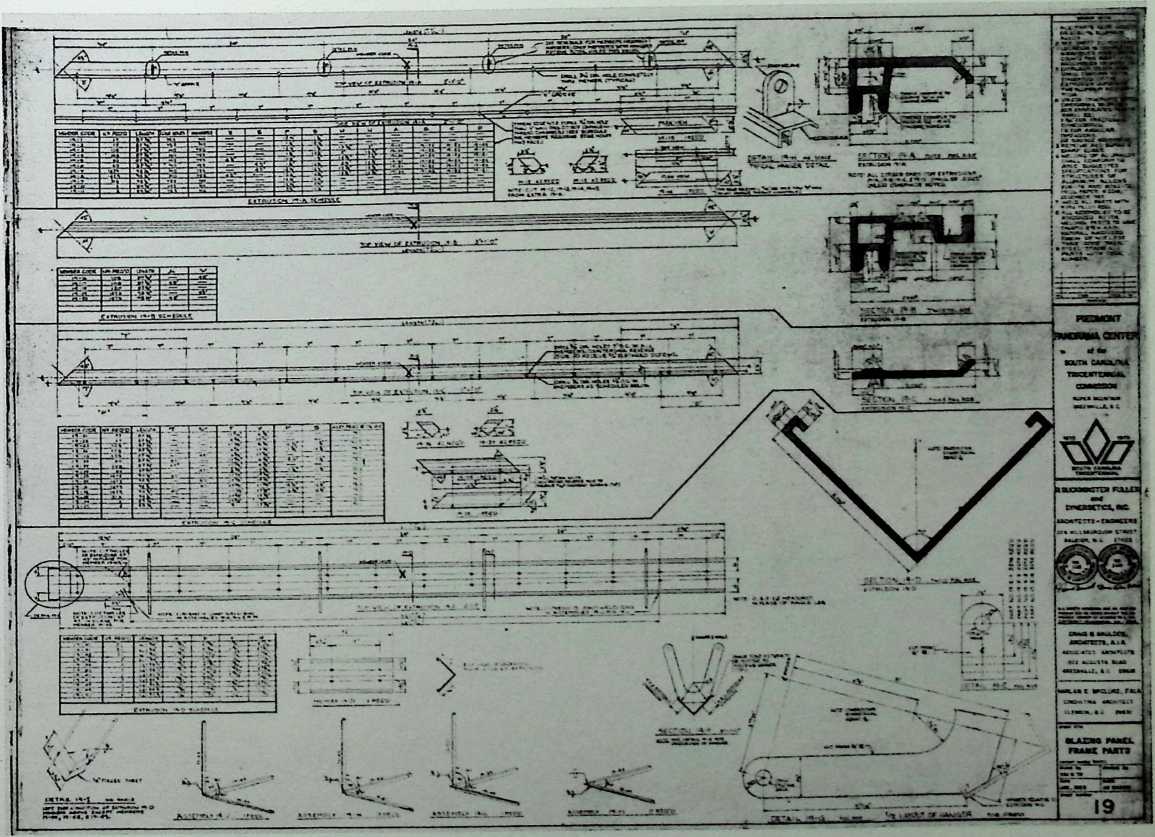
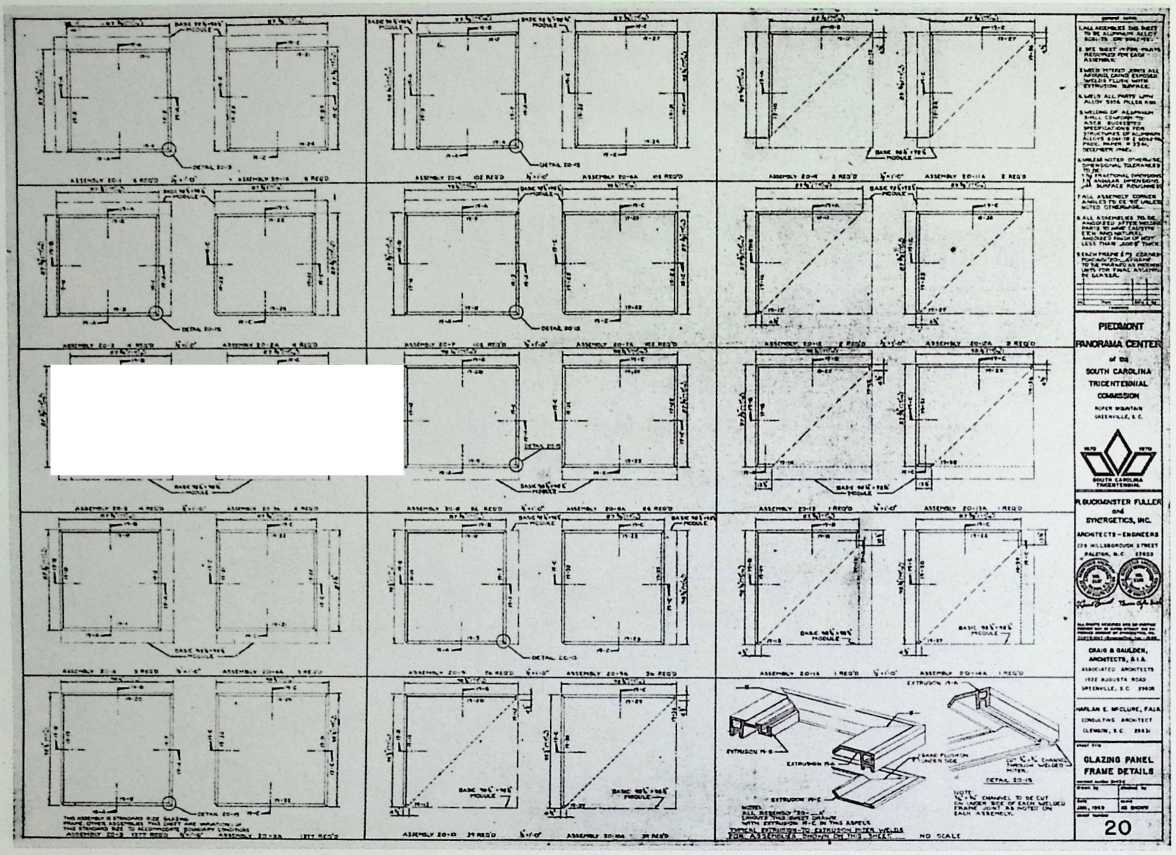
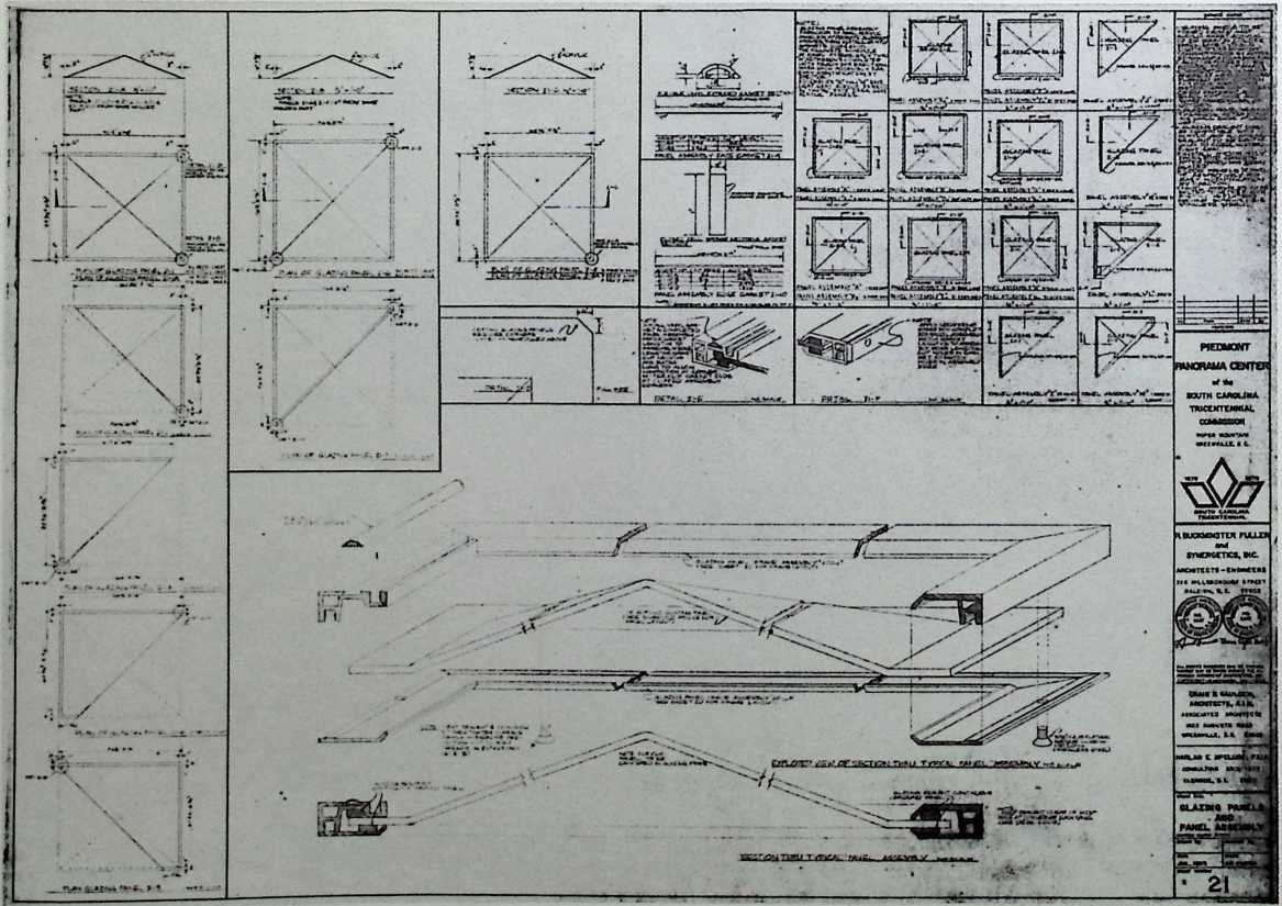
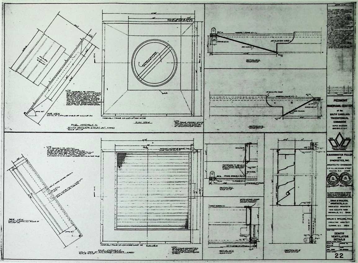
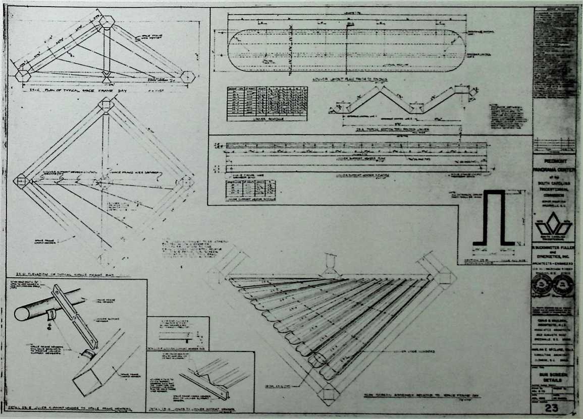
¶ Chapter 23 Piedmont Panorama Center for the South Carolina Tricentennial 1969–1970
The Piedmont Panorama Center was to be a twelvesided volume composed of octet trusses and sited on a hill.
II
BWORAMA CENTER
RBUCXMMSTER FULLER
EAST ELEYATrOJl
PIEDMONT
SOUTH CAROL! MA
TR1CENTEXNIAL

PIEDMONT
31NORAMA CENTER
SOUTH CAROLINA TRICtNTtNNt AL CCAAC13.0H
SOUTH-EAST
WALL
![]()
![]()
![]()
![]()
iSUTH-WUT MLL
10
PEMXT ,*N0RM4A CTXTTM
II
■I • • ! !
190 THE GEODESIC REVOLUTION. PART 2
n
L_
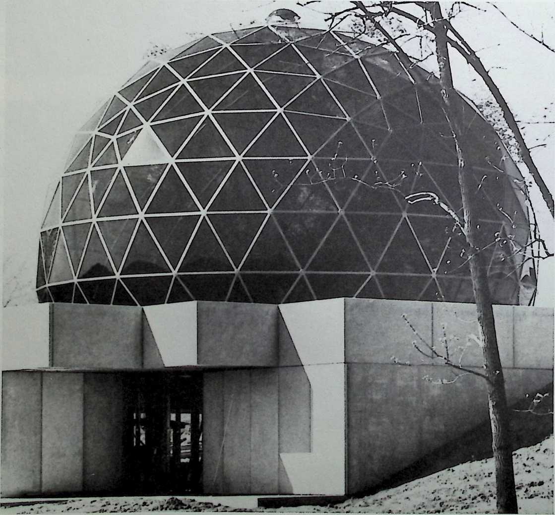
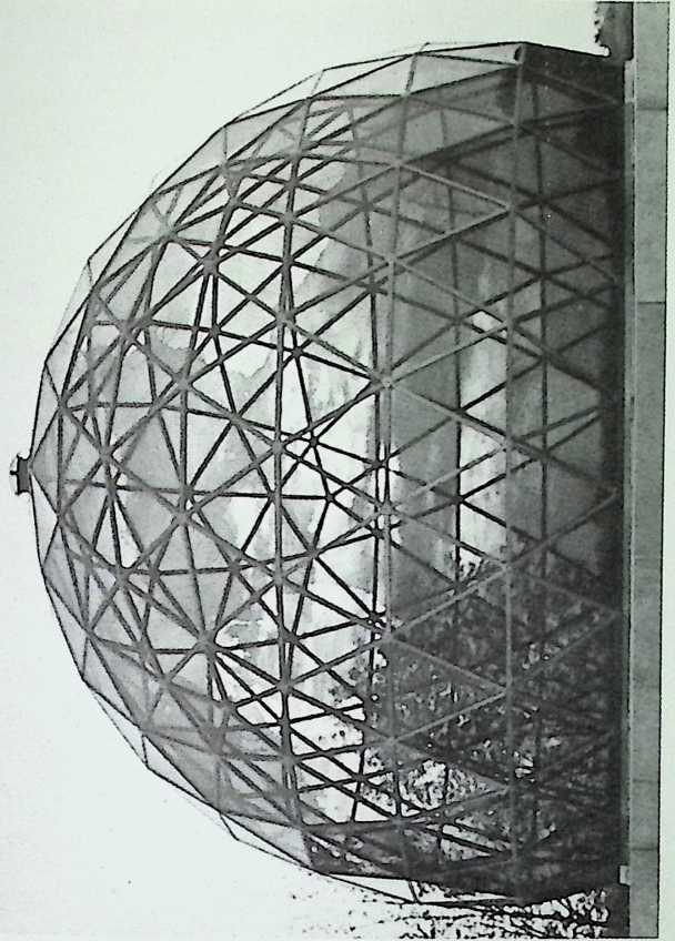
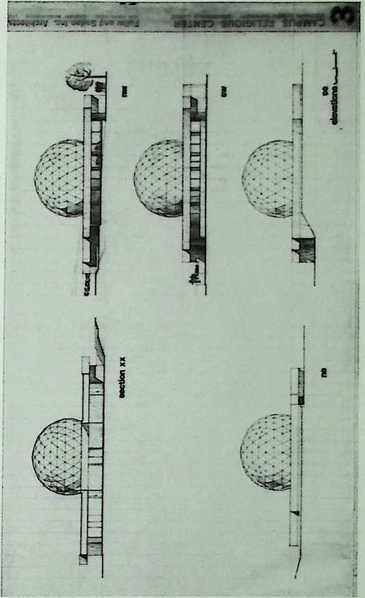
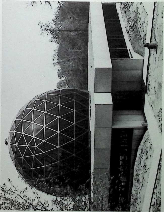
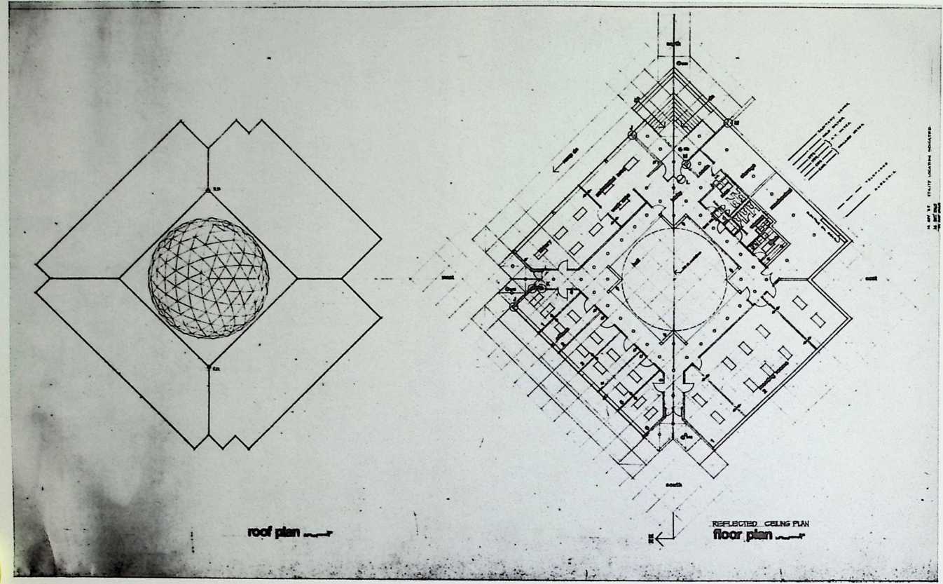
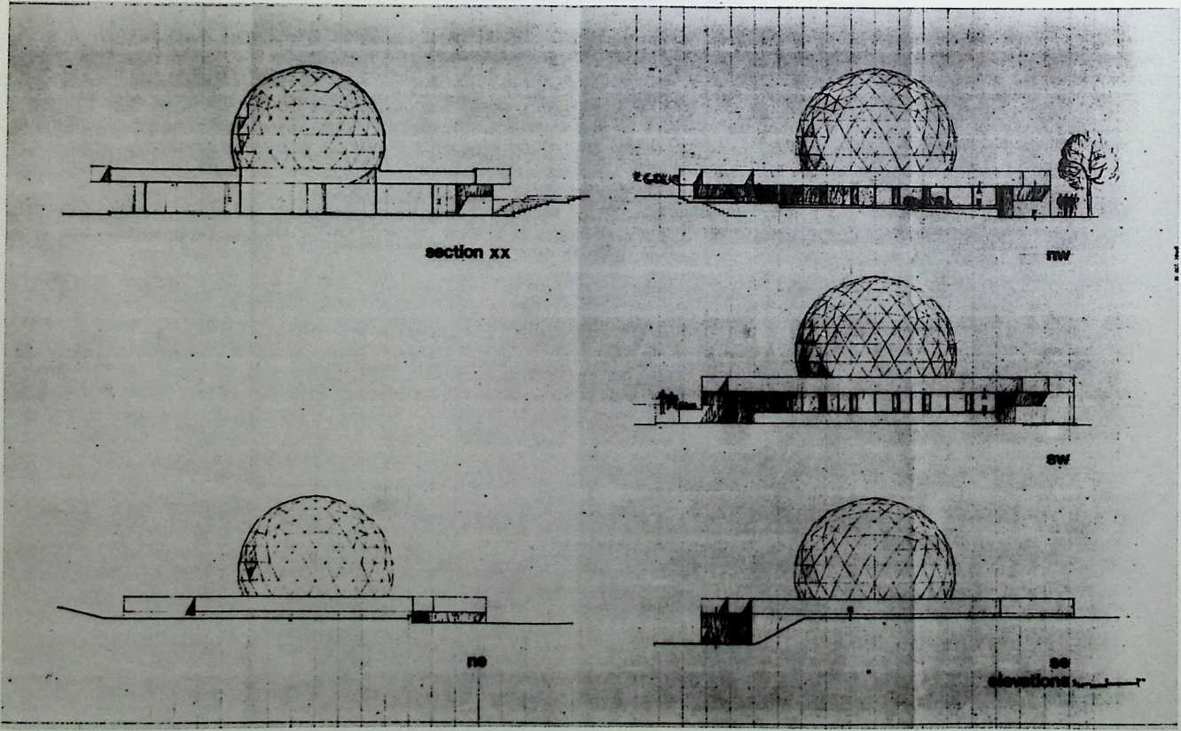
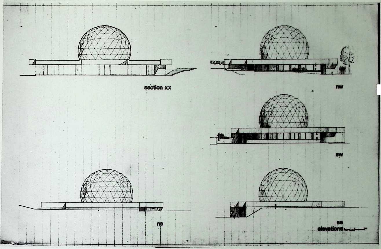
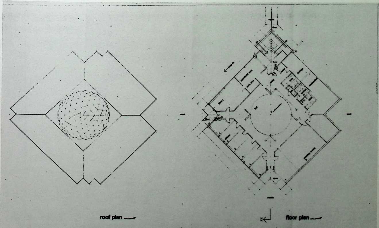
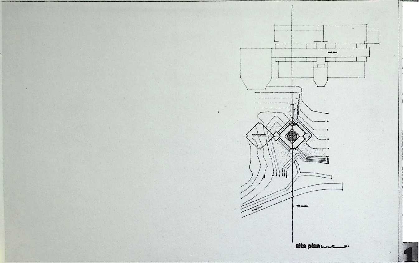
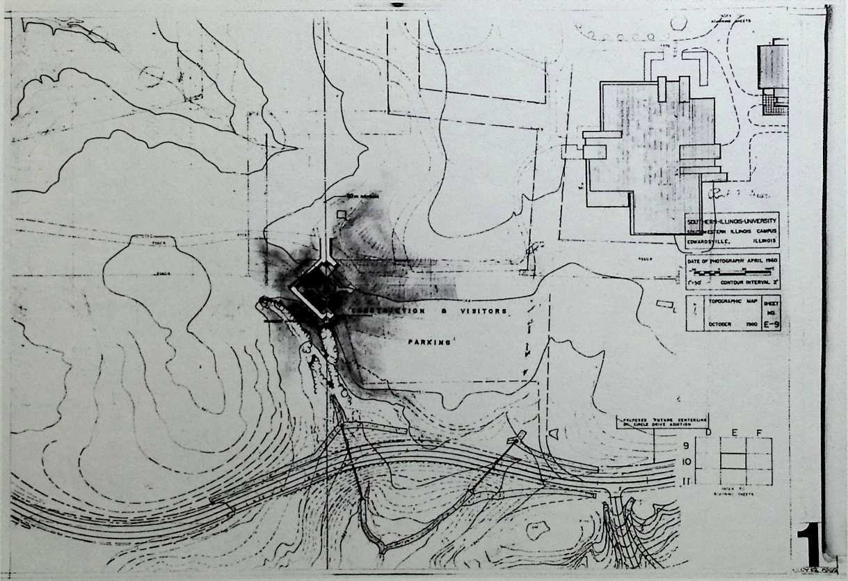
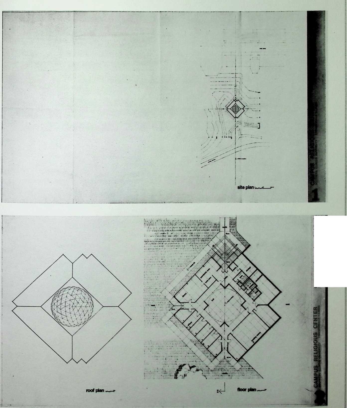
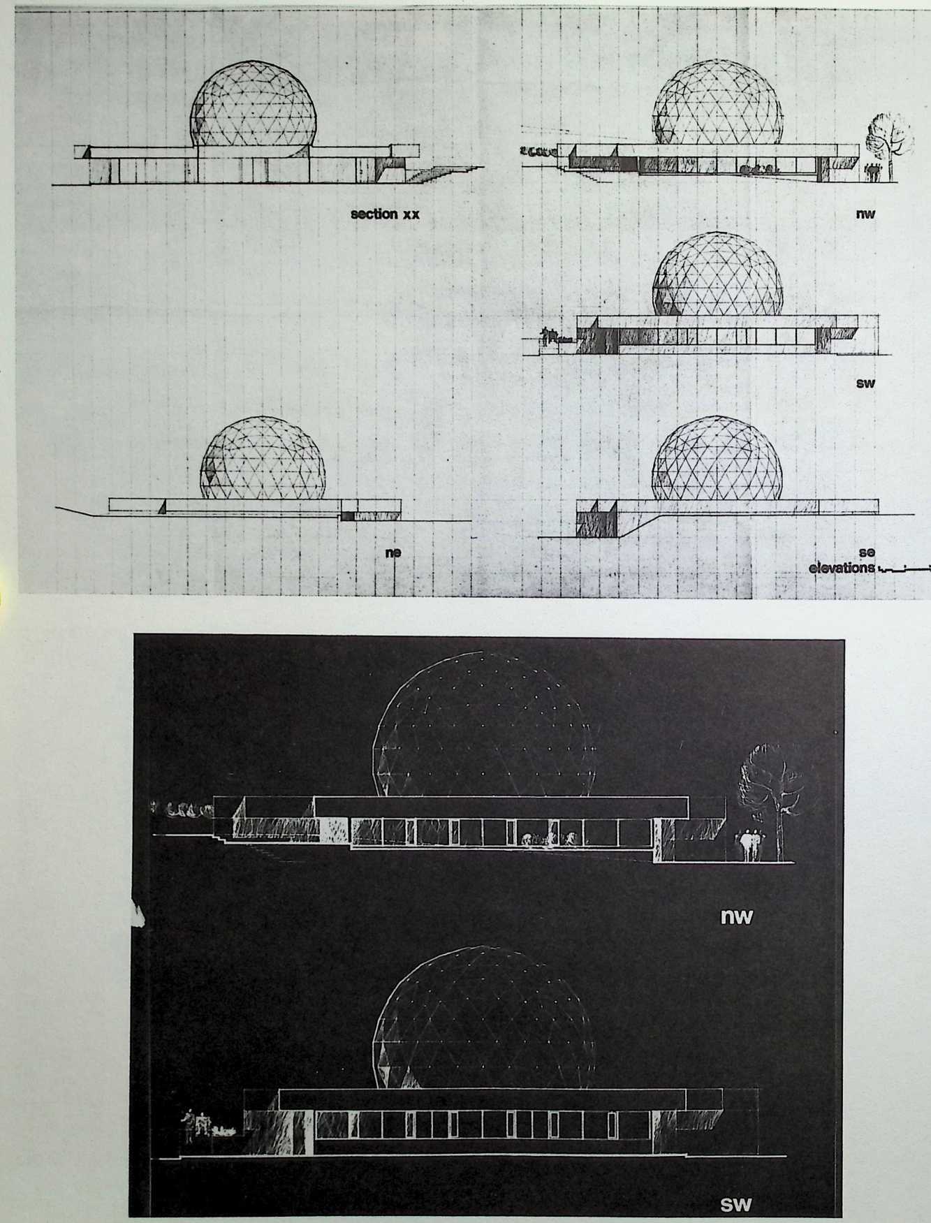
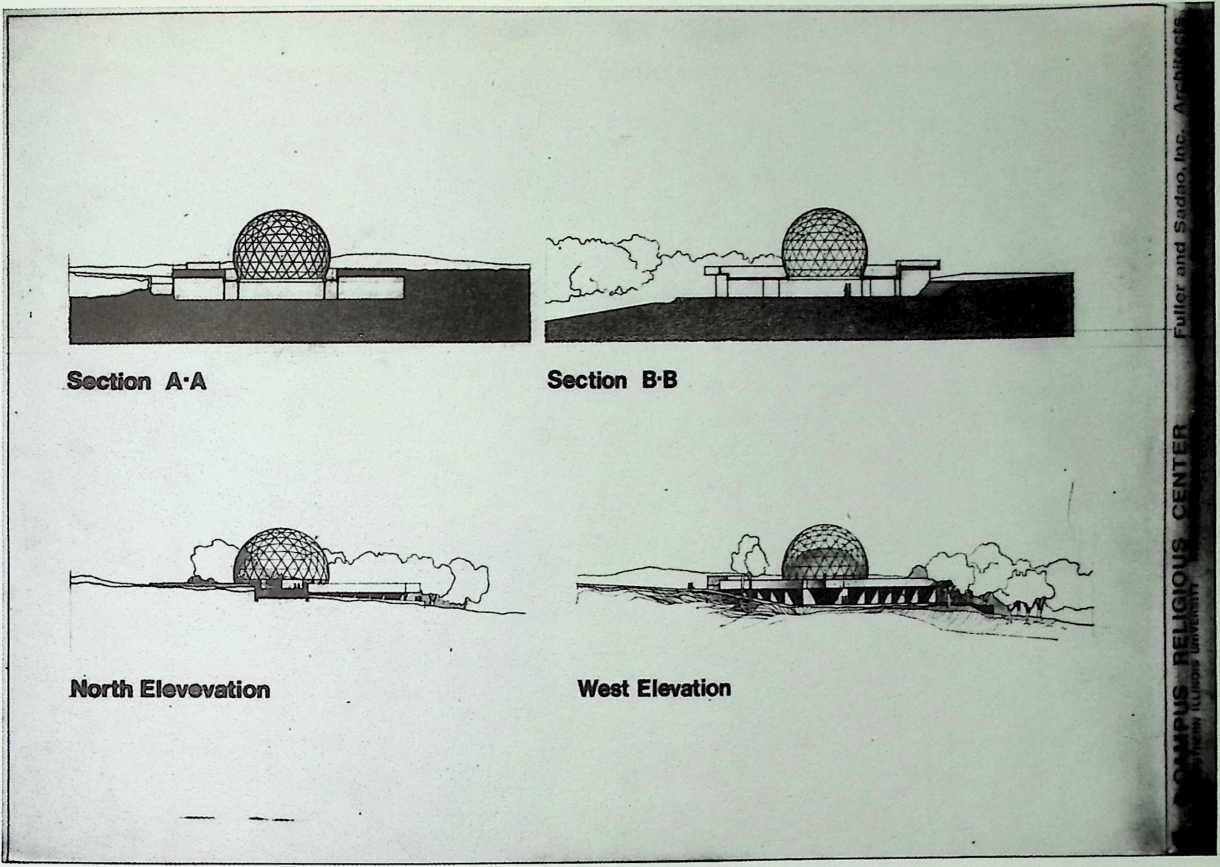
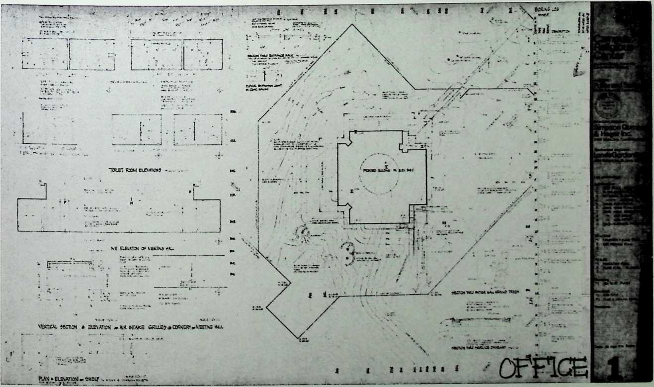
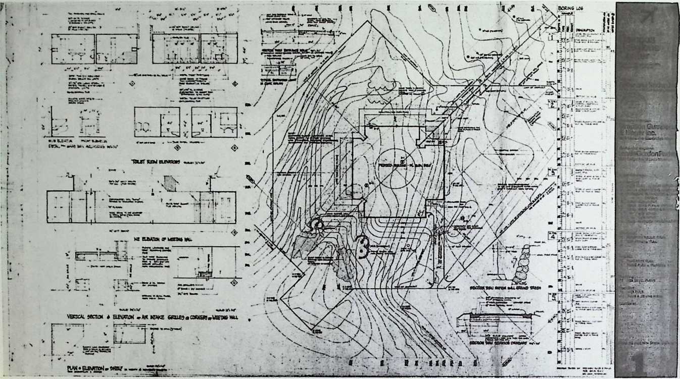
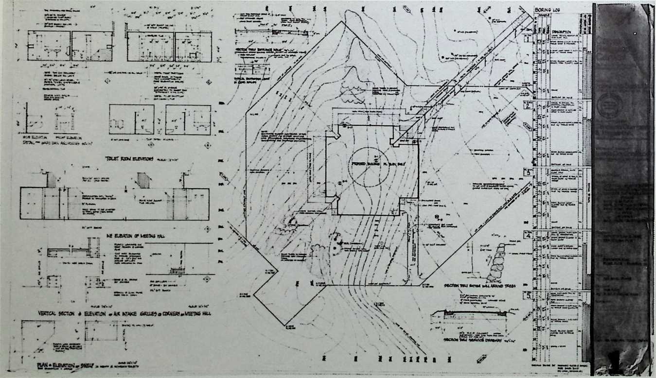
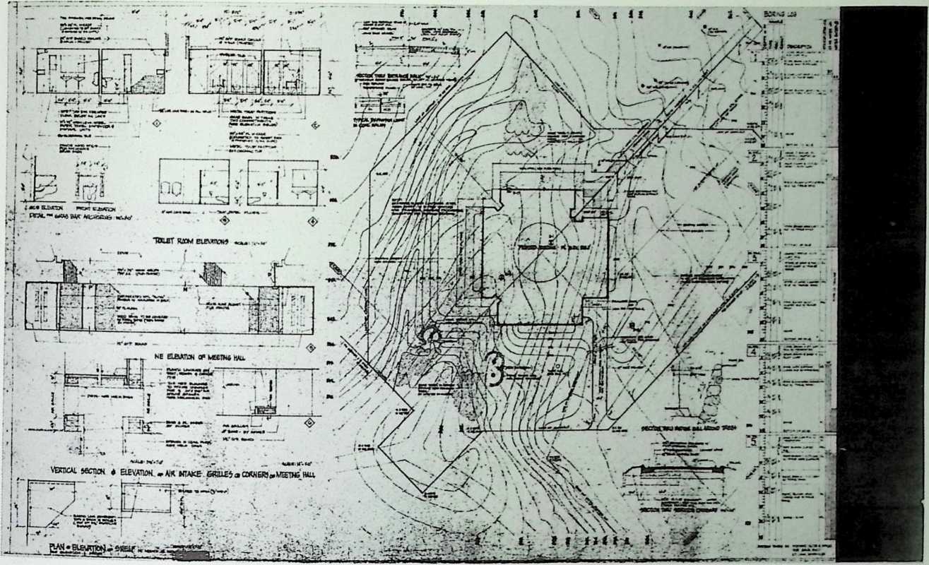
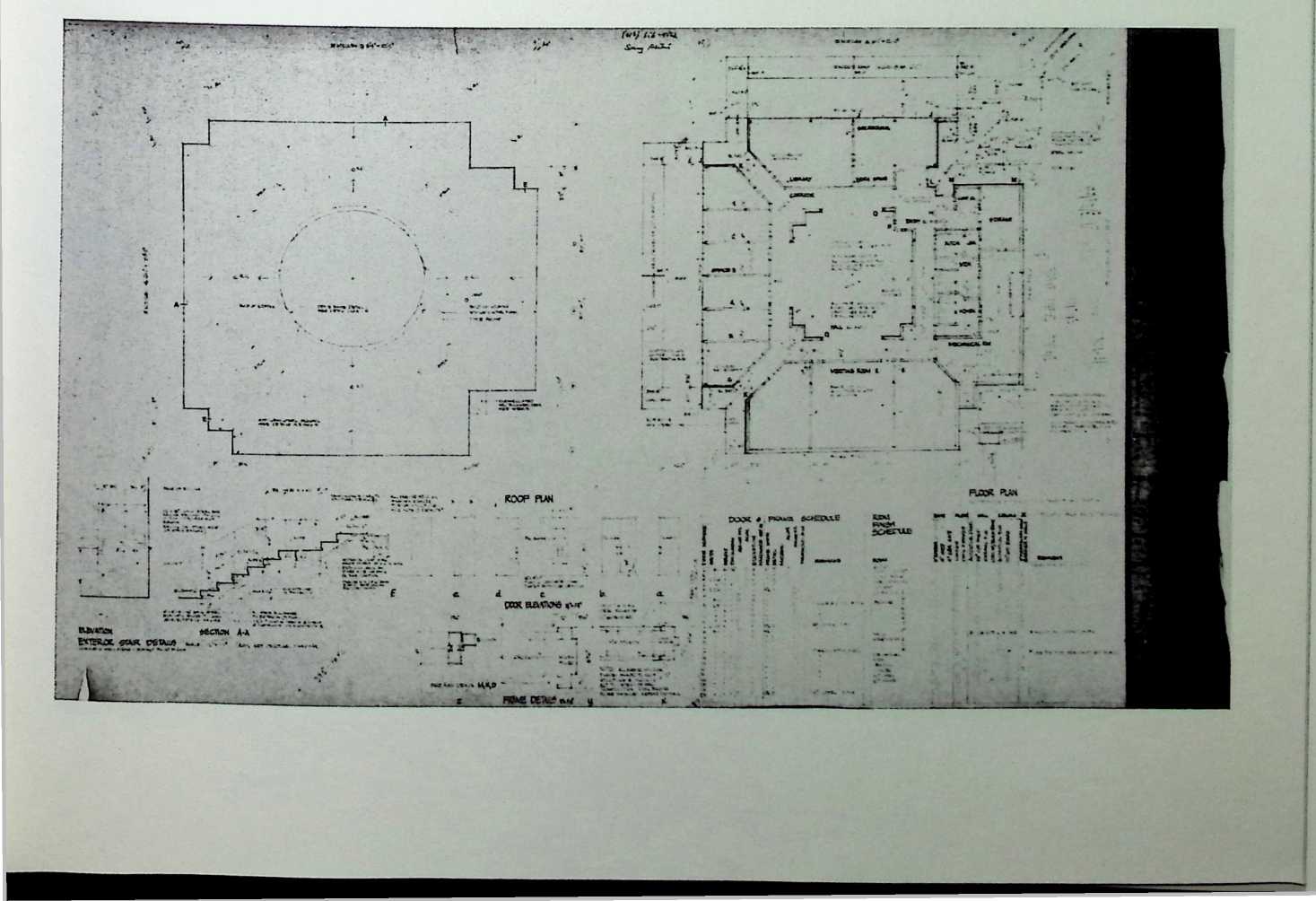
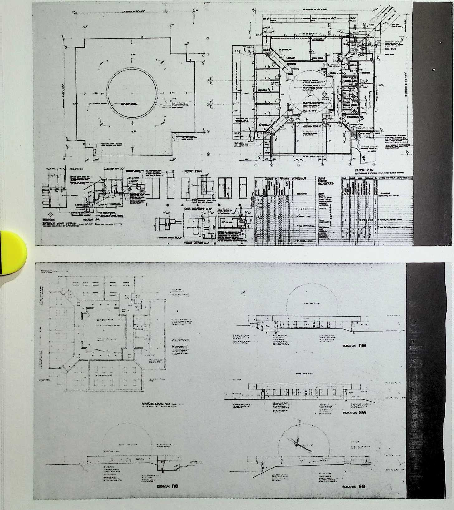
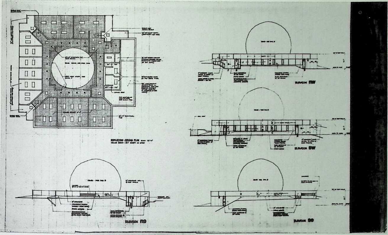
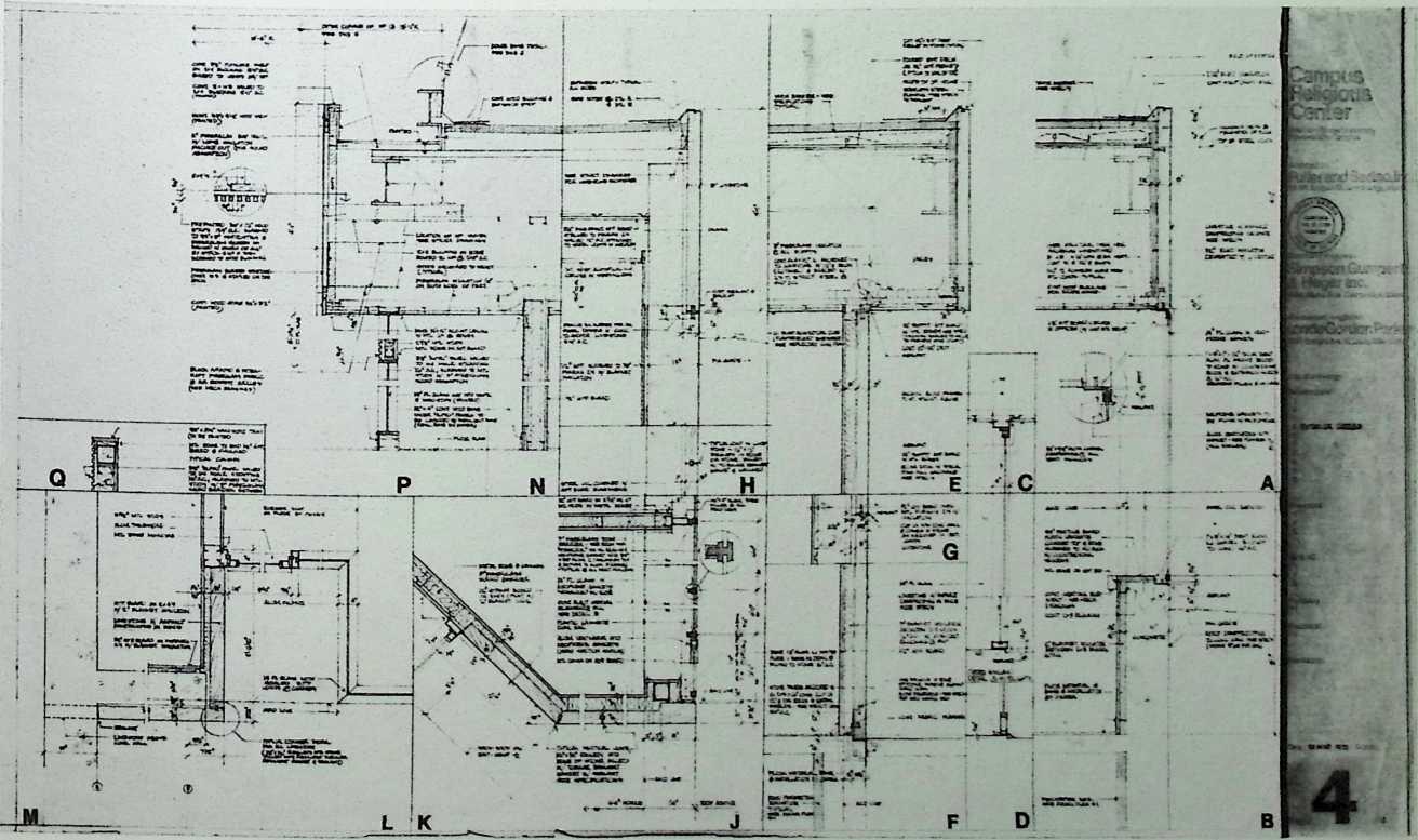
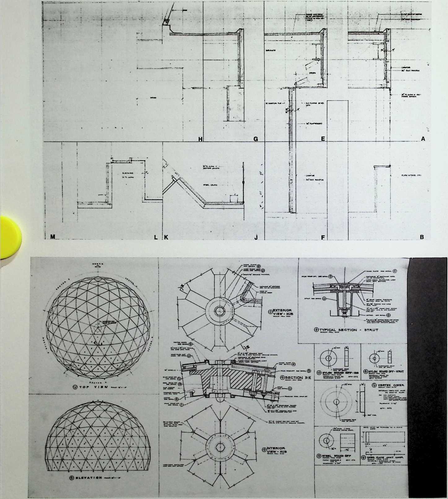
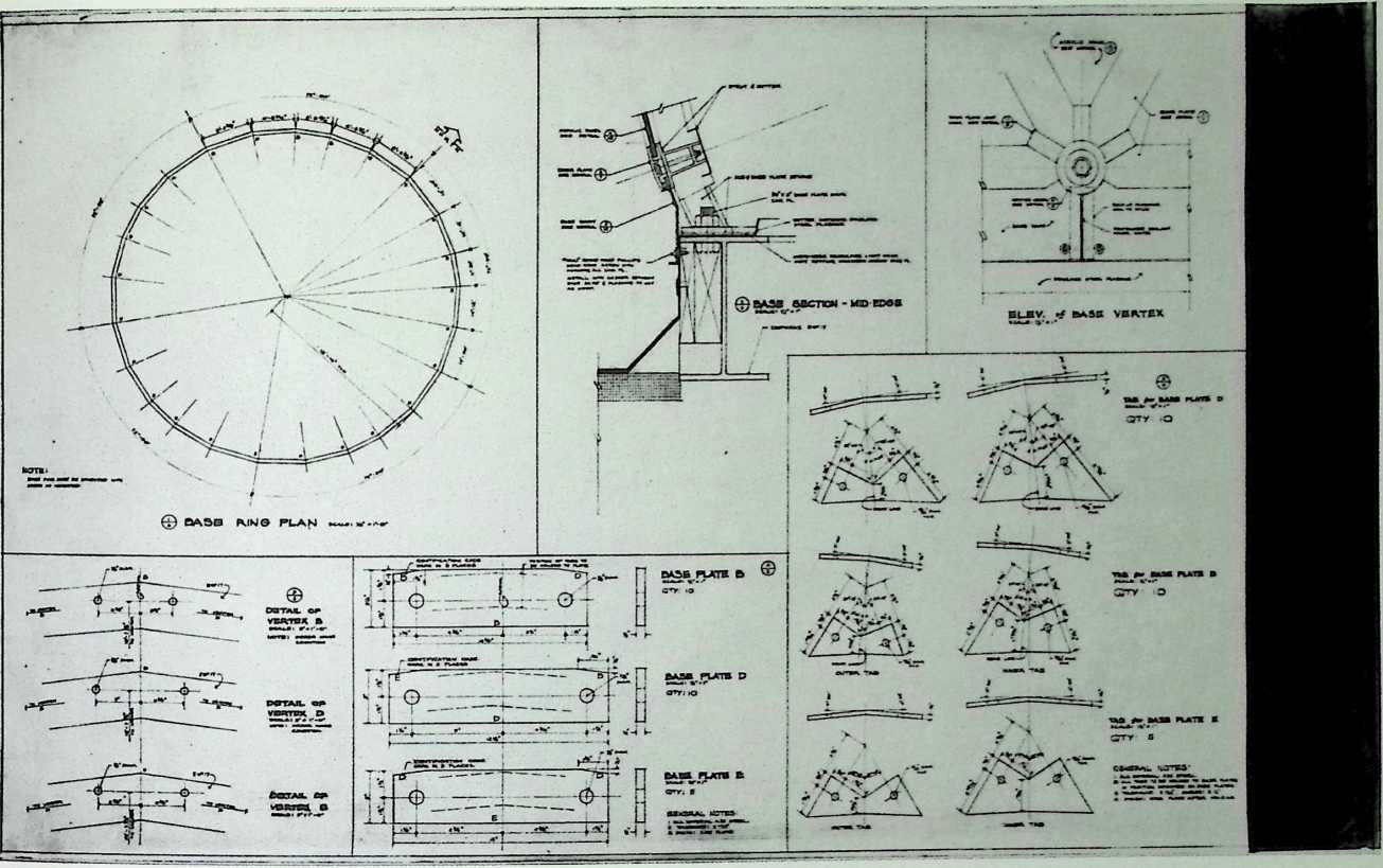
Campus Religious Center, Southern Illinois University, Edwardsville Fuller & Sadao (Designed by Shoji Sadao and Karlis Grinbergs), 1969
This center was designed to accommodate any denomination. Sadao’s treatment of the masonry base and sunken entrance and Fuller’s dome of black glass and silver mullions combine to produce one of the most elegant geodesic structures extant.
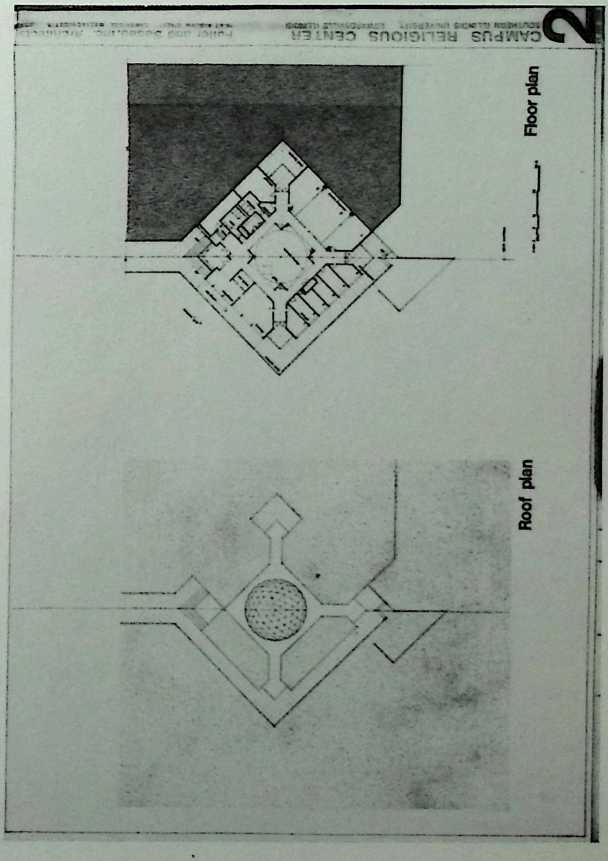
CAMPUS RELIGIOUS CENTER Fuller and Sadao, inc. Architects
SuTHEFIN ILLINOIS UNIVERSITY EDWARDSVILLE ILLINOIS , wur tuauw. sntrn c*Mon>aar »»•
fuller and Sadaojnc. Architects, I U-r., ul*
![]()
WWUm biLVM ww
¶ Chapter 24 Vault for Quincy Market, Boston Fuller & Sadao, 1969
This proposal for Quincy Market comprises a series of octet trusses that, in tandem with the masonry construction of the colonial market, emphasizes the lightness of Fuller’s technique. Ultimately, a more conservative restoration of the market was adopted.
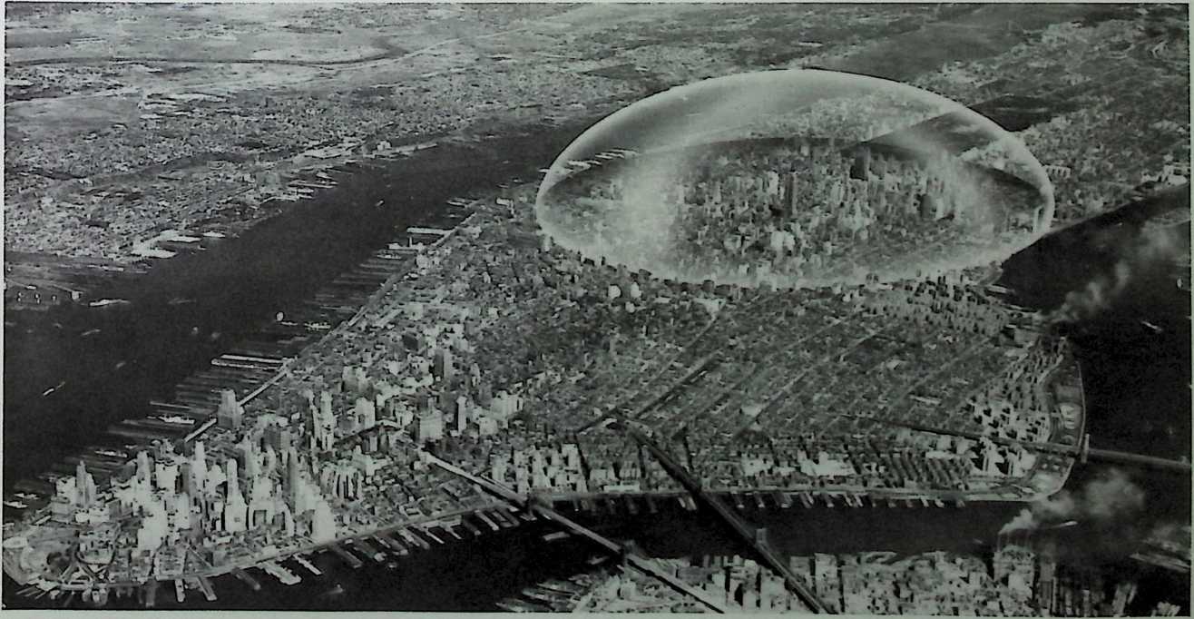
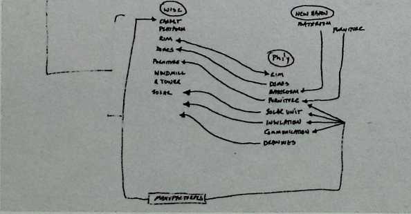
These three projects characterize three phases of Fuller’s plan to make his metaphor Spaceship Earth’ a reality. The first and best known of these is the hypothetical geodesic dome for New York City, the diameter of which would have covered fifty blocks of Manhattan Island (1960). From Fourteenth to Sixty-fourth streets and from the East River to the Hudson River the city becomes a single room. But this dome mainly was meant as a daring graphic metaphor to suggest the possibility of controlling the effects of sunlight and the quality of air.
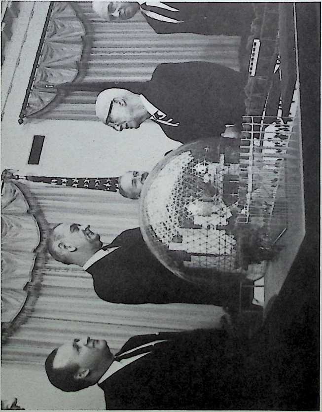
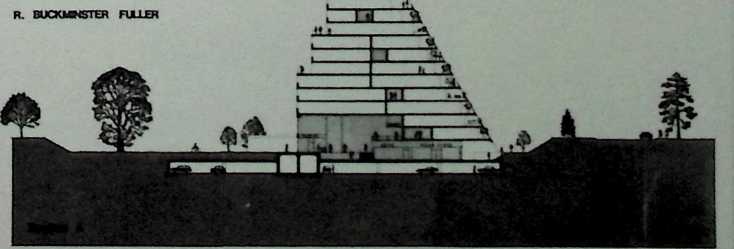
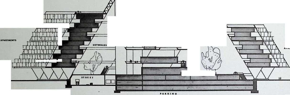
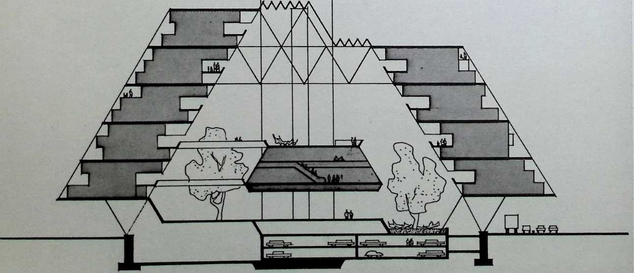
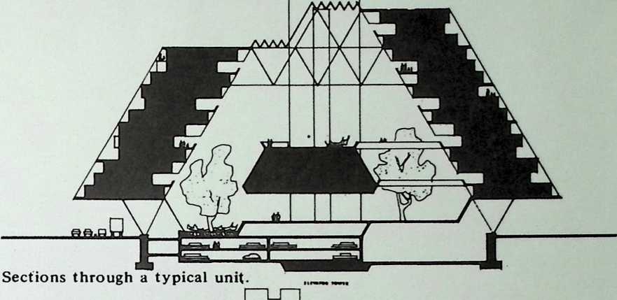
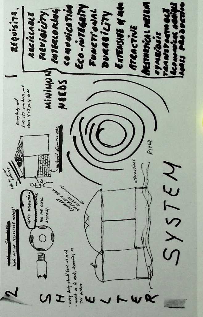
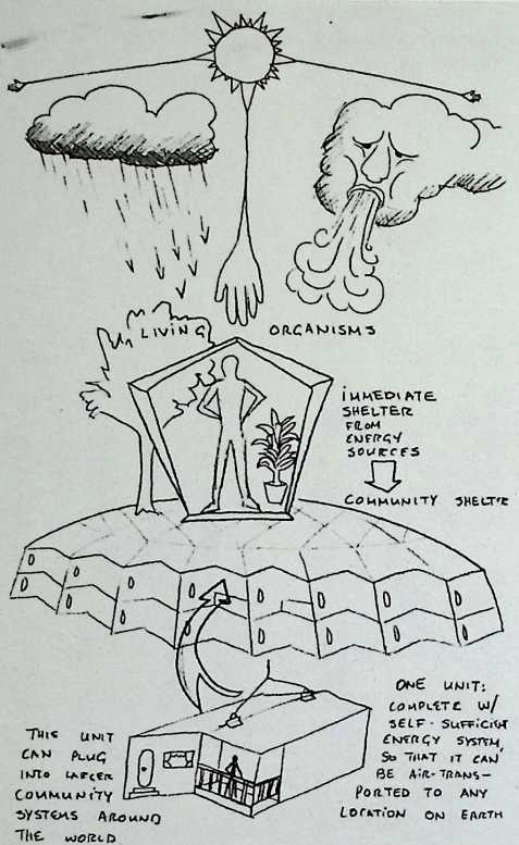
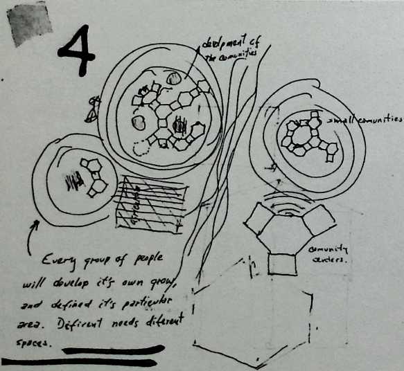
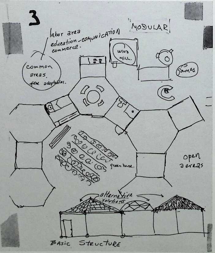
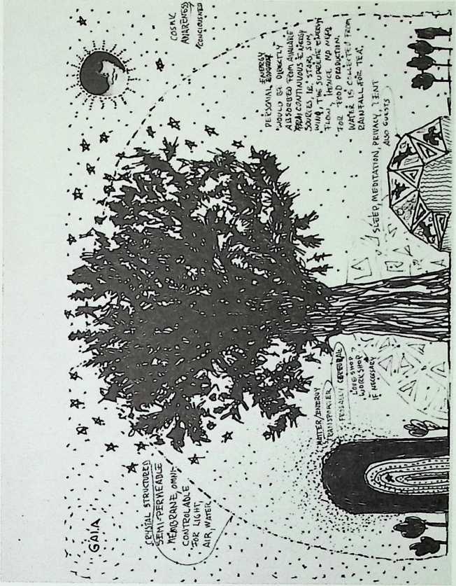
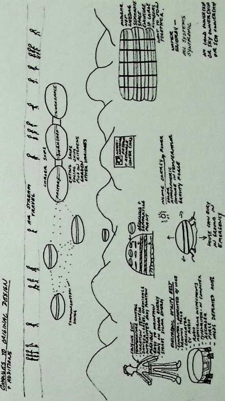
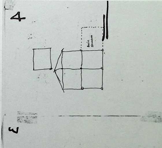
¶ Chapter 25 Three Utopian Projects 1960–1970
Developed during the late sixties, the tetrahedron city was to be two miles wide and two miles high. It would have housed 300,000 families and would have been hollow. In fact, it would have been buoyant enough to float at sea. Thus the time and money usually required to obtain land could be redirected to the quality of the structure itself.
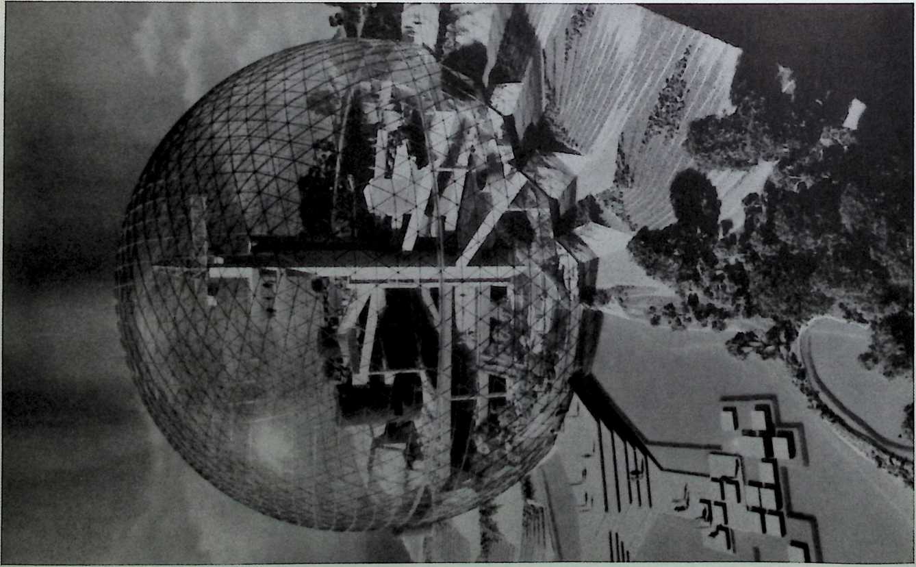
Finally in the late sixties, Fuller produced a scheme for floating cities housed by geodesic spheres up to a mile wide. Like the floating city, the airborne globes would have required no land. Their independence from earth would have made the flying spheres Fuller’s first domestic satellites.
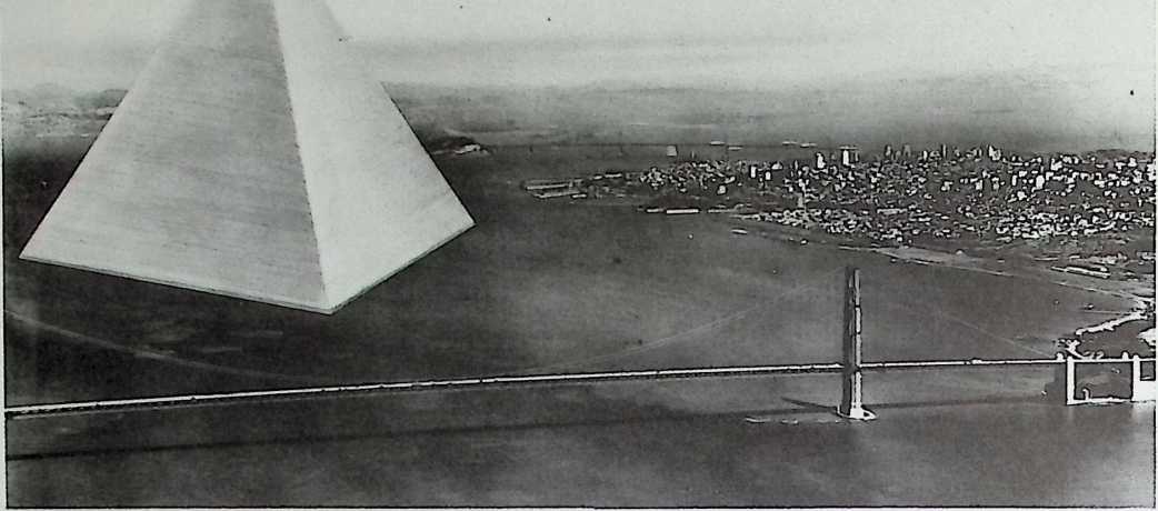
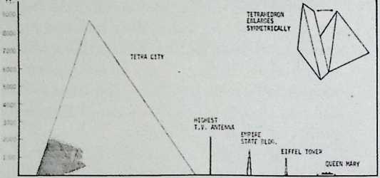
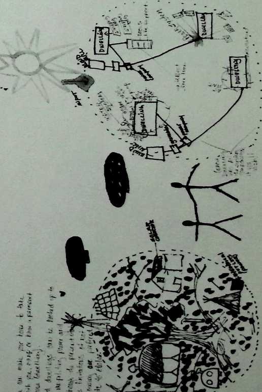
We find that 1 tetrahedronal city, to house a nil- Hcn people, it both technologically and economic- ally feasible. Such a vertical-tetrahcdronal-city can be constructed with all of itstbrec hundred thousand families each having balconied ‘‘outside* acartrents of t»o thousand square feet floor space. All of the machinery necessary to its operation will be housed Inside the tetrahedron, it is found that such a one nil lien passenger tetrahed- ronal city is so structurally efficient, and therefore so relatively lioht, that together with its hollow bov sectioned reinforced concrete foundations it can float. Such tetrahedror.al floating cities would rasure Uo riles to an cdie, and can be floated in a triangularly patterned canal. This ■ill make the whole structure earth-.uaic-croof. The whole city can be floated cut into the ocean to any point and anchored. The depth of its foundations will go tclow the turbulence level of the seas so that the floatin‘) tetrahedrons! island will be, in effect, a floatin’) triangular atoll. Its t»o nile long toat‘ foundations will constitute landing strips for jet airplanes. Its interior ti.o nile harbor will provide refuse for the largest and smallest ocean vessels. The total structural and rcchanical materials involved in production of a nu-ber of such cities are within feasibility rannitude of the already operating retals manufacturing capabilities of any one company of the several major industrial nations around the earth. The tetrahedron city >*ay start with a thousand occupants and grew symmetrically to hold nil lions without changing overall shape though always providing each fanily with 2C0 $j. ft. of floor space. Withdrawal of materials fror obsolete buildings on the land will ;emlt the production of enough of these floatin-: cities to support frequently spaced floatini cities cf various sites around the oceans of the earth. This will permit etd-ocean cargo transferring and therewith an extraordinary increase of efficiency Of the Inter-distributicn of the world‘s raw enJ finished products as well as of the passenger traffic. Three quarters of the cart- is covered ty water, fan is clearly intent on penetrating those >.-orld-around ocean waters in every way to work both their ocean totters and their marine life and chemistry resources. Sue*’ ocean passage shortening habRais of ever trar - lent humanity will remit his individual fl.r i sailing, economic steoning stone travel arcund the whole Earth in nan/ directions.
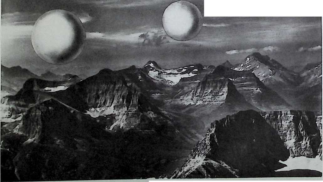
A ere hundred fact di are ter erodes II Sphere we‘<;htrg three terns encloses seven tors cf air. Th* air to structural weight ratio is TH. Mhrc we double the site so that geodesic severe H i’W feet in deleter the weight of tr« structure goes up to 1 tors while the •eight of the air gees up to 56 tors — the air to structure ratio charges to 8/1. en «• dcuble t‘-e sire ejain to a KO *«l geodesic sphere – ire size c* several geodesic dxxs row operating -• the weight cf the air irside czei to alout 585 tons wMle the wei’/l cf Ve structure goes up to 15 tons. Air weight to structure weight ratio <s row 2J»1. -e get to a geodesic sphere c-ne- ►alf rile tn dicrxUr, Ve weight cf the air c-cU-.ed <5 so groat t‘at the weight o’ the structure itself becoces c< relatively negligible magnitude for the ratio is 1,800/1. When the sun shines on an open frar* aliral- n_n geodesic sphere of one-half nile diameter the sun penetrating through the frame and reflected fren the ccncave far side, bounces back into the sphere and gradually heats the interior a tr-c sphere to a did degree. When the interior temperature of the sphere rises only ere degree Fahrenheit, the weight of air pushed cut of the sphere is greater than the weight of the spherical frame geodesic structure. This roans that t*-e total weight cf the interior air, plus the weight cf the structure, is «uch less than the surrounding atmosphere. This nears that the total asse-btage, of the geodesic -i-nrrc and ns contained air, will rave to fkat outwardly, into the sky. being displaced by the heavy atmosphere around it. When a great bank of nist lies in a valley in the coming and the sun shines upon 1t, the sun heats the air Inside the bank of nist. The heated air expands and therefore pushes soce of itself outside the nist bank. The total assembly of the mist bank weighs less than the atmosphere surrounding It and the nist bank floats aloft into the sky. Thus are clouds manufactured. As geodesic spheres get larger than one-half allo in diemeter they Lccane floatable cloud structures. If their surfaces were draped with outwardly hung polyethelene curtains to retard the rate at which air would coca* back in at night, the sphere and Its internal atu>- sphere wculd continue to be so light as to remain aloft. Such sky- floating geodesic spheres ray be designed to float at preferred altitudes of thousands of feet. The weight of hiasan beings added to such prefabricated ‘‘cloud nines’’* would be relatively negligible. f»any thousands of passengers cculd be boused aboard one nile diameter and larger cloud structures. The passengcri cculd core and go frtn cicud to cicud, or cl0.3 to ground, as the clouds float around the earth or are anchored to rvyjntaln tws. KM It the building of such floating cicuds is several decades hence, «e cay fersee that along with the floating tetrahedrcnal cities, air-deli«- crable skyscrapers, submarine tsla-ds. sub-dry surface dwellings, dor-ed-cver cities, flyable dwelling cachir.es, rentable. autcncccus-ii»lr»g, plack toes, that ran «say be able to converge and deploy arcurj earth witrcut its depletion.
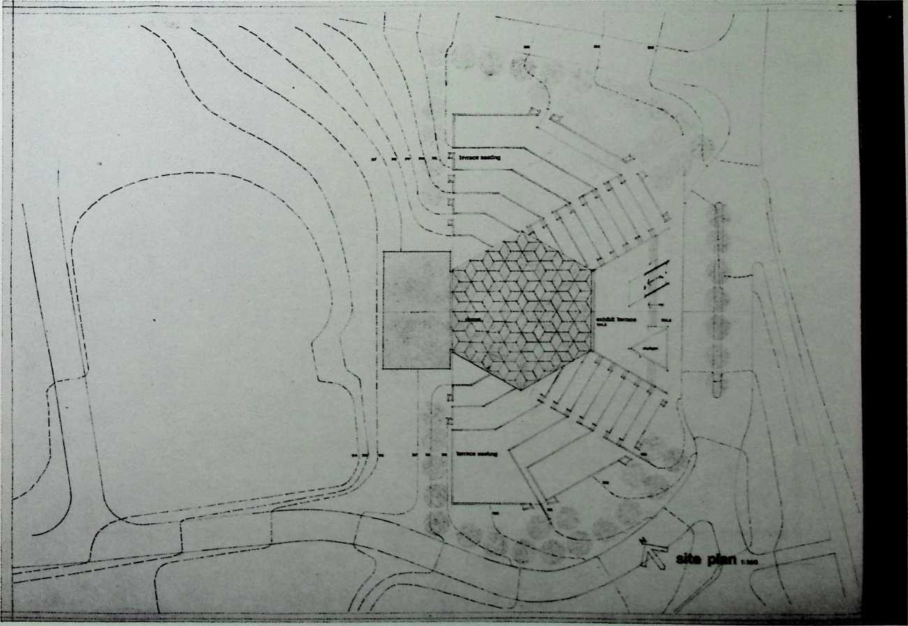
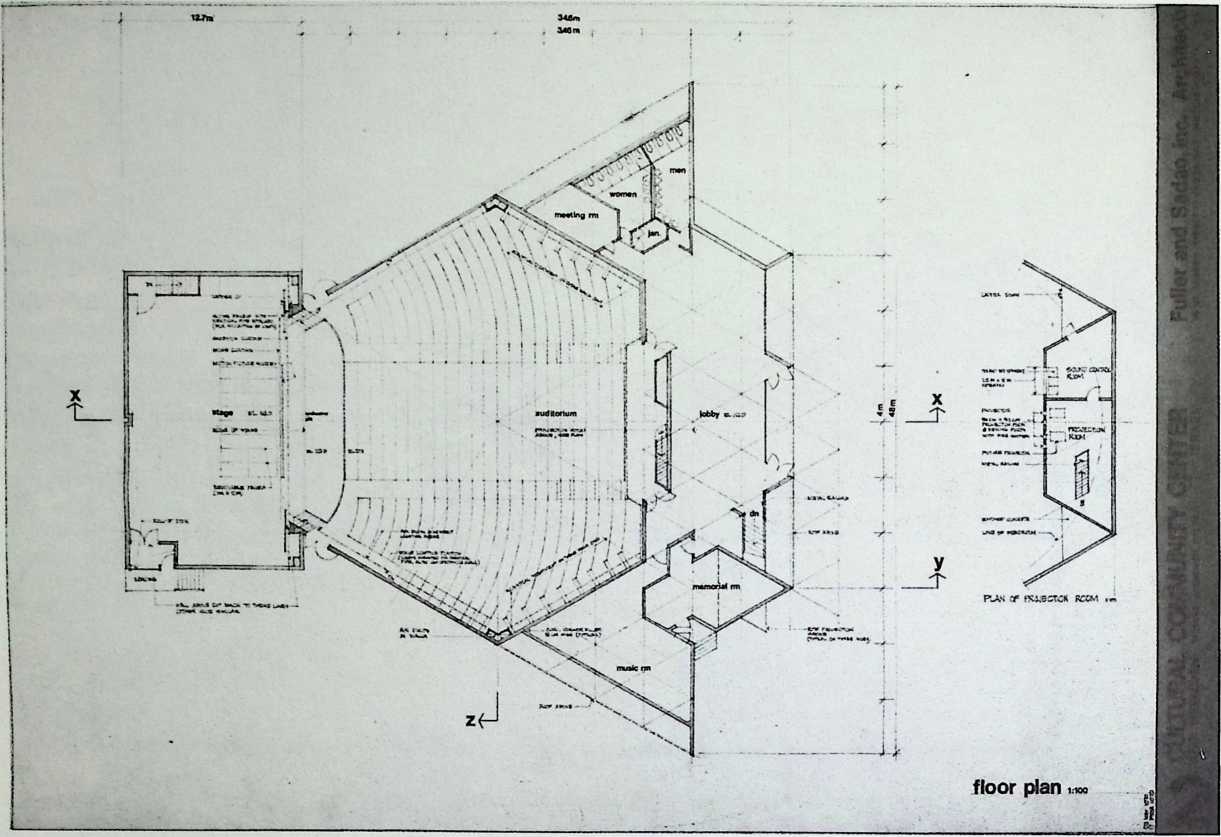
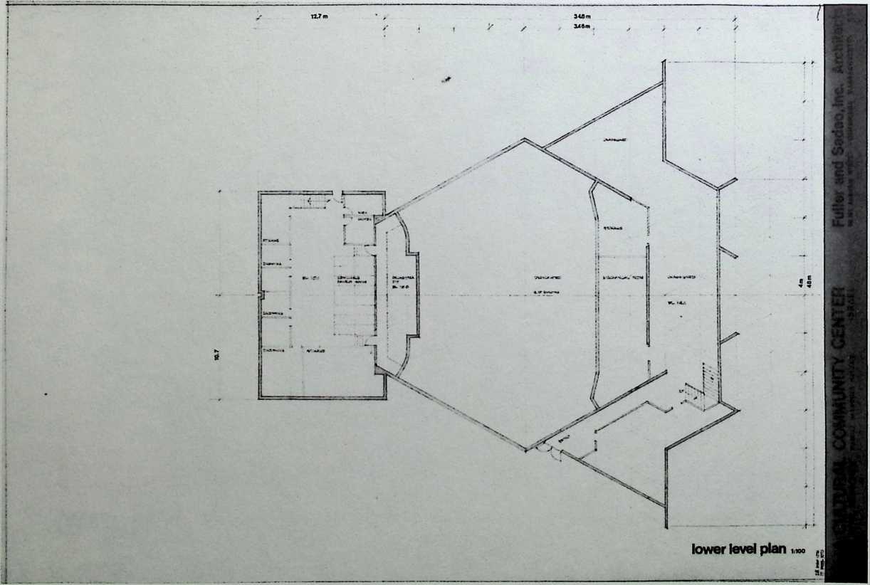
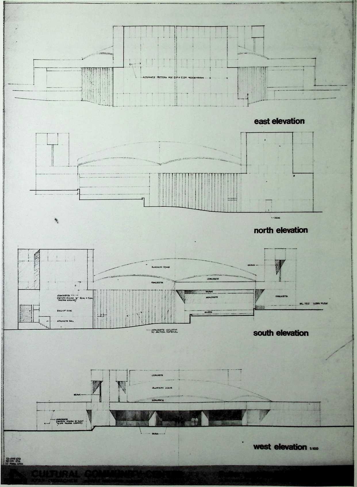
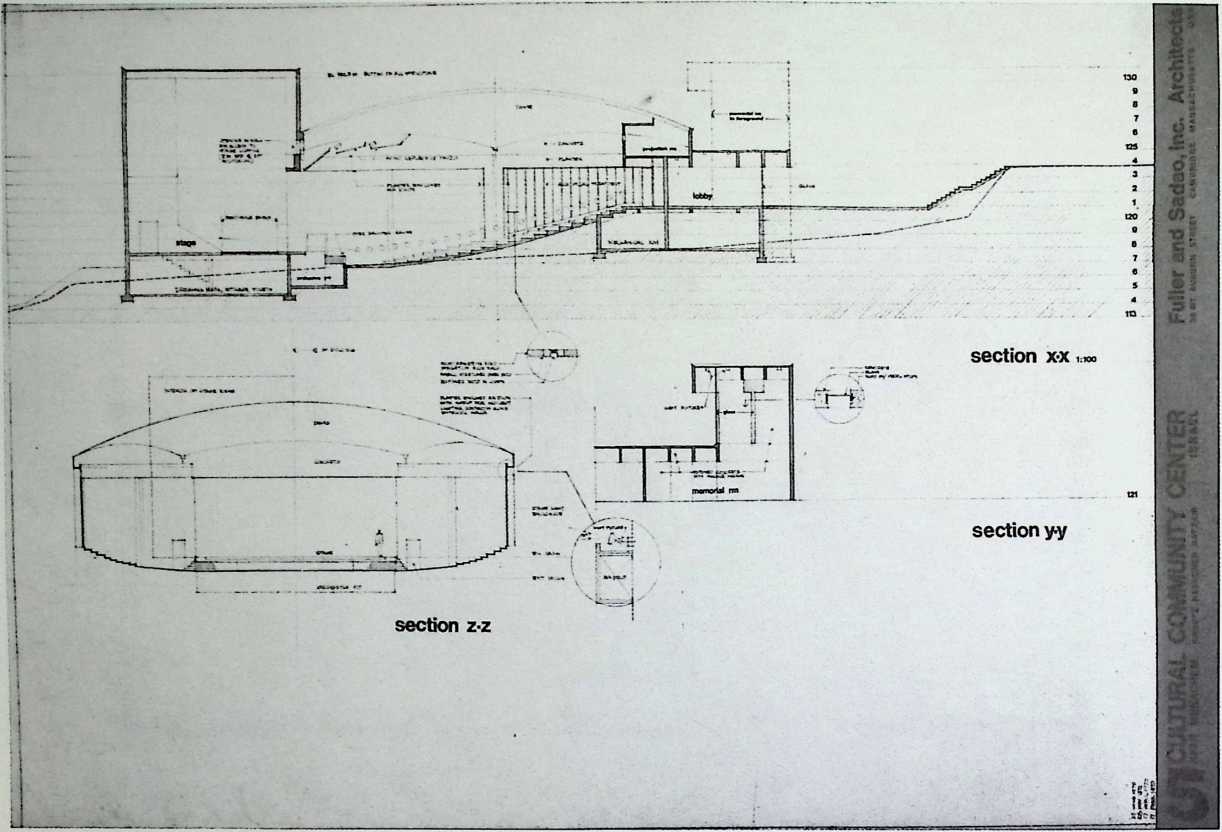
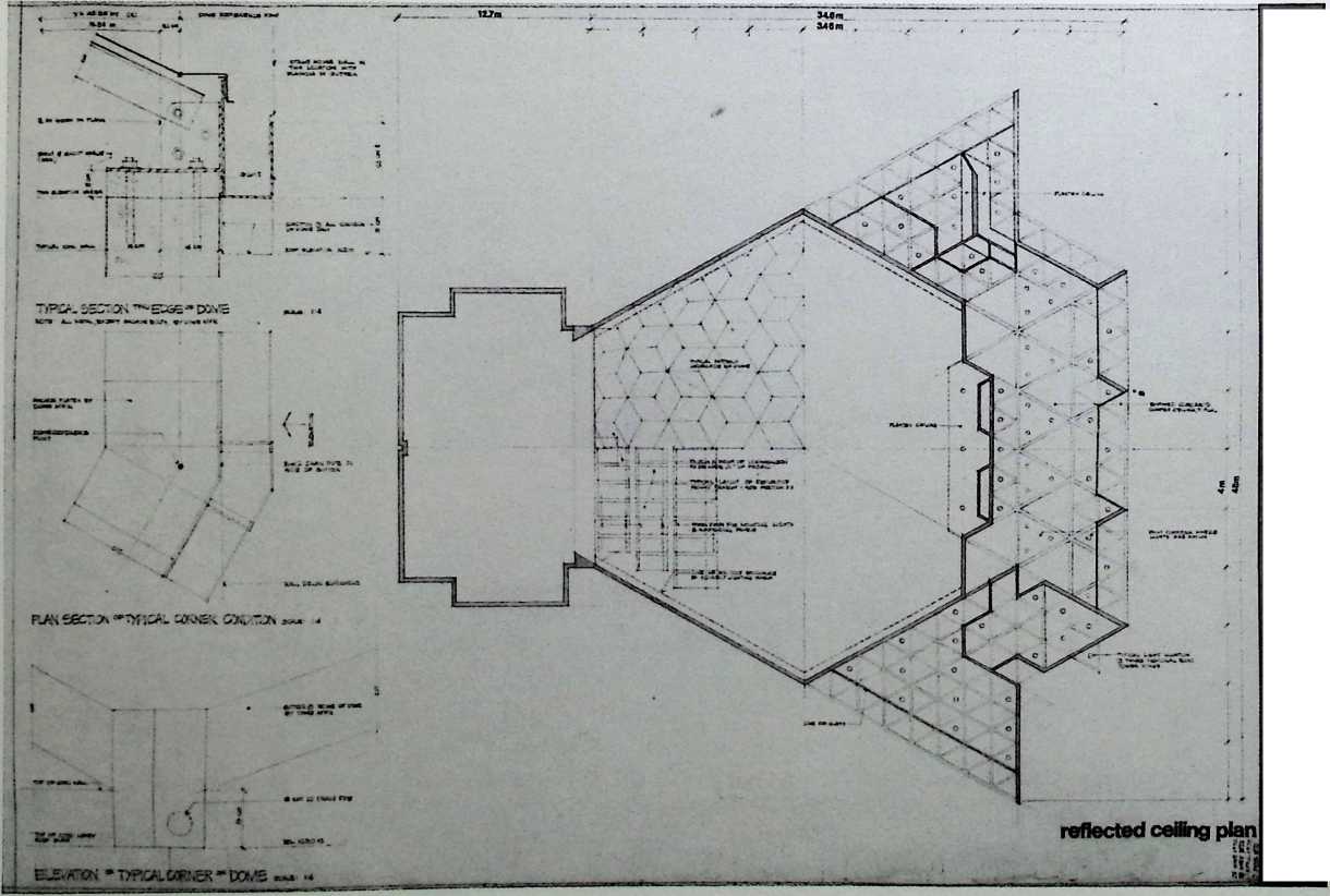
¶ Chapter 26 Cultural Community Center, Kfar Menachem, Kibbutz Kashomer, Hatzair, Israel Fuller & Sadao, 1970
The composition of the Kfar Menachem Cultural Center is a hexagonal auditorium set into a triangular building. Flanges of terrace seating radiate from its exterior sides and the stage is an appended rectangular pavilion. It was constructed primarily of reinforced concrete and panels of prestressed concrete. The pattern of the coffered ceiling is complemented by Fuller’s hexagonal pan vault, which covers the auditorium. This structure is topped by an aluminum dome on the exterior.
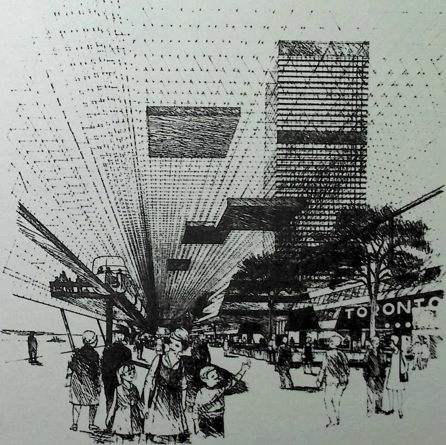
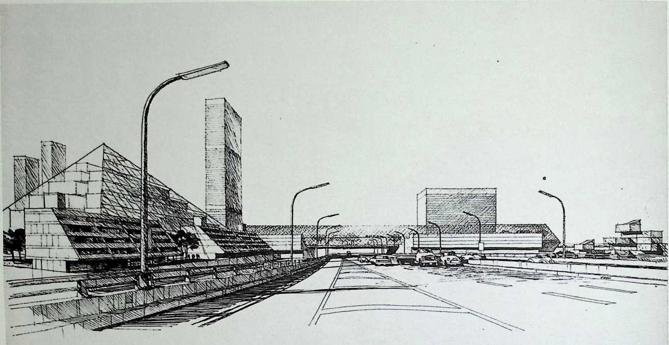
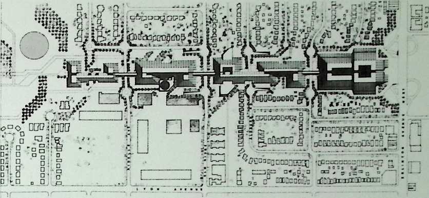
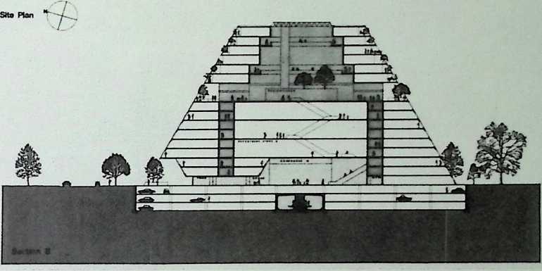
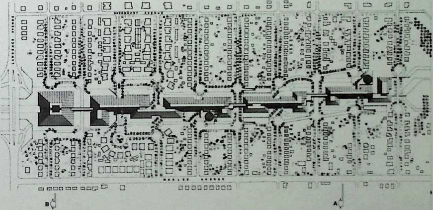
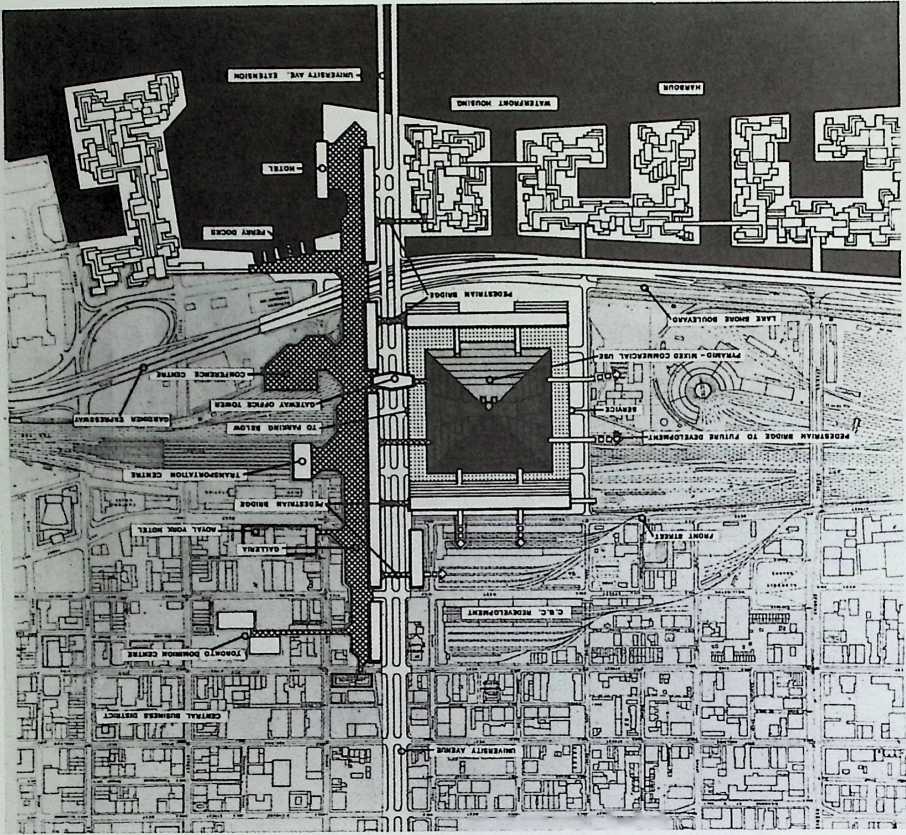
¶ Chapter 27 Project Spadina, Toronto, Canada Fuller & Sadao, 1970
The idea behind this example of advanced urban renewal is the consolidation of several functions in one megastructure running along one traffic artery . From the air this complex would have resembled crystalline growth with its central concourse enclosed dramatically by a glazed octet truss system. The truss, in addition to the concrete pilings, would have been the main building supports. Apartments, stores, business offices, and a monorail would have made this city within a city nearly self sufficient, and the complex geometries of the constituent buildings would have made it architecturally ahead of its time.
HOT WATER TO
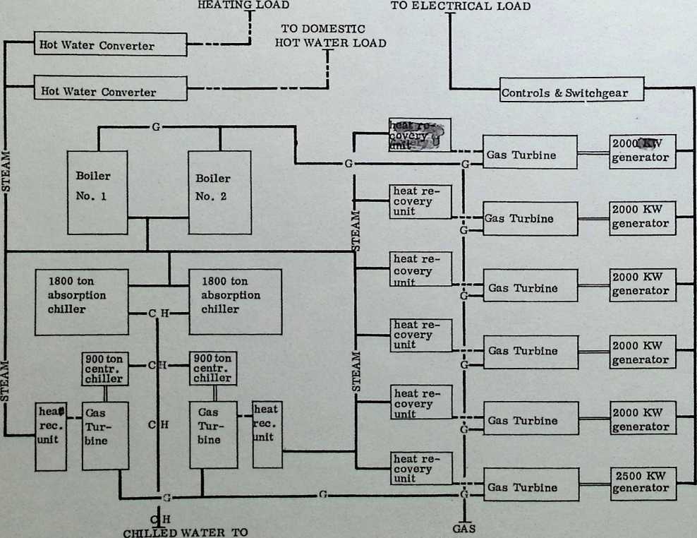
SUPPLY
AIR CONDITIONING LOAD
PROJECT SFADINA
CONCEPTUAL PLAN
(LEVATOR TOWER
wavatayayayaw
SKYLIGHT
7
kYAYAYAYAYAYAYAVAYAVAYAYAYAYAT
UNIinH
ftwwmri
— . ft --±=7
1 | I / INTERIOR GAADIN
i sX,. W
APARTMENTS
![]()
![]()
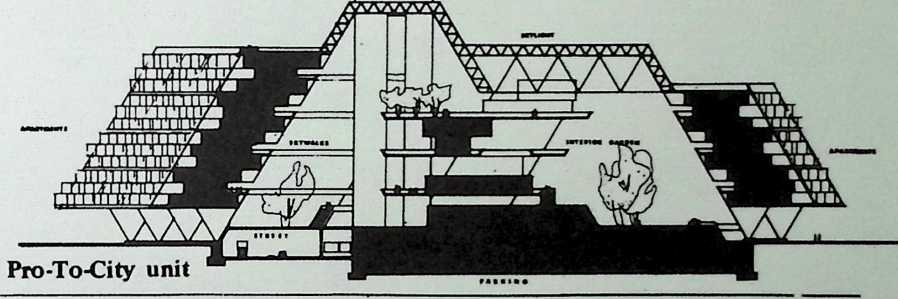
Spadina expressway Sections through the megastructure.
mi n.frimr drafter
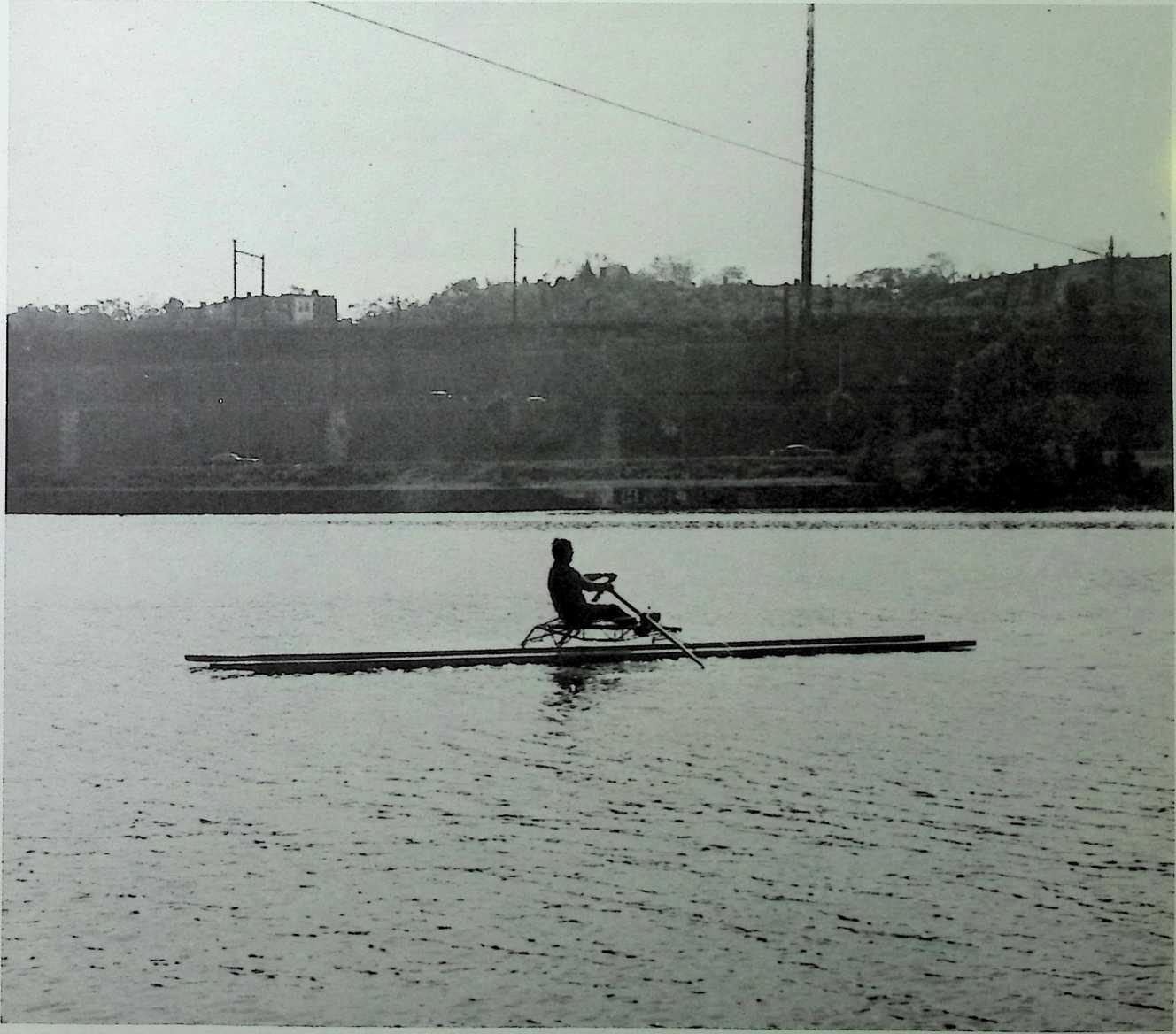
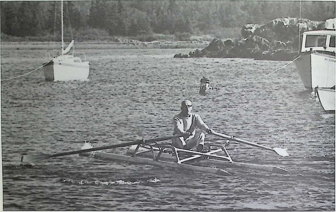
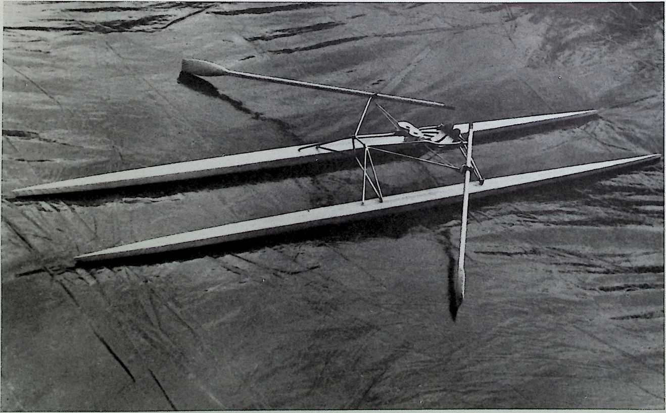
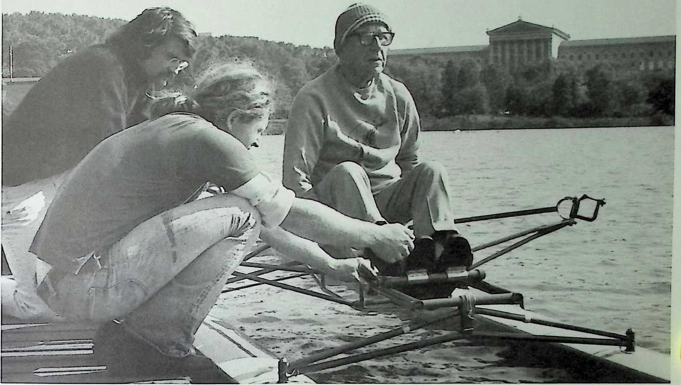
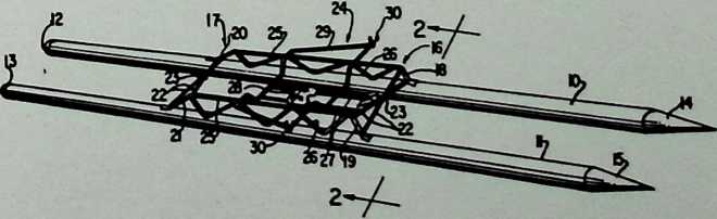
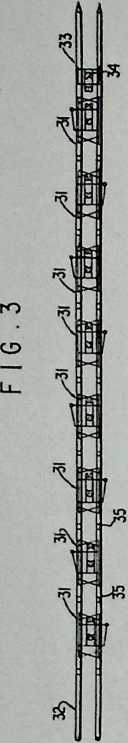
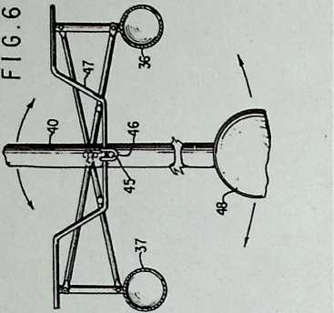
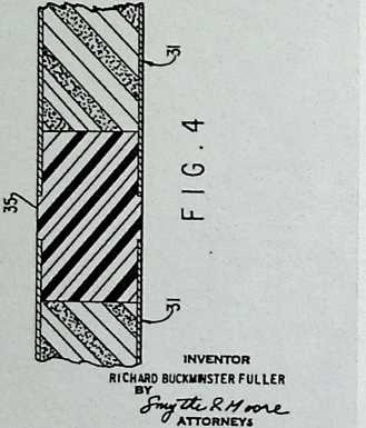
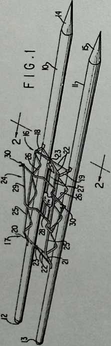
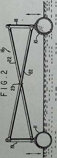
Rowing Needles (Watercraft) Patent 8/18/70
This invention is actually a catamaran that one can either row or sail. Its two pontoons are watertight so that the vessel cannot founder even if overturned.
nil 3,524,422
United States Patent
Oil
Inventor
(21]
(221
(451
Appl. No.
Filed Patented
Richard Buckminster Fuller
P. O. Box 909, Carbondale. Illinois 62901 716,957
March 28,1968
Aug. 18,1970
2.685.270 8/1954 Pierac 9/2X
3.179.960 4/1965 Nimmo 9/2
3,236.202 2/1966 Quadyelal 1I4/6IX
3.273.528 9/1966 Kiefer „…114/61
Primary Examiner— Andrew H. Farrell Attorney—Smythe and Moore
(54) WATERCRAFT
10 Claims, 8 Drawing Figs.
(521 ll-S.CL 114/61
[51] lat.CL B63b 1/14
[50] Field of Search 114/61,
22.26,27;9/2S
(56] References Cited
UNITED STATES PATENTS
612,920 10/1898 Winquistetal 115/26
1,190,569 7/1916 Maxwell 9/2
2,341,166 2/1944 Todd 114/61
ABSTRACT: A watercraft useful for rowing, sailing, and the like, wherein there are two spaced substantially parallel float members, the float members being joined by longitudinally spaced transversely extending structural means, each structural means including a vertically extending post, means, or column on its float, the tops of said posts being joined by al least one structural cross member extending therebetween so as to keep the floats parallel or al the desired angle relative to each other and so as to inhibit rolling thereof relative to each other.
Patented Aug. 18, 1970
3,524,422
sh««t or s
Patented Aug. 18, 1970
3,524,422
Patented Aug. 18, 1970
Sheet I or 3
3,524,422
INVESTOR RICHARD BUCKMINSTER FULLER
Sheet 3 of 3
V ATTORNEY €
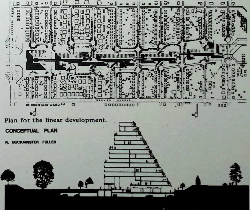
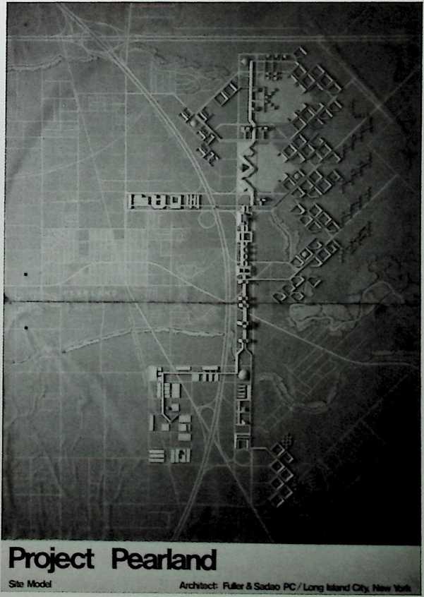
¶ Chapter 28 Project Pearland, Pearland, Texas Fuller & Sadao, 1971
Project Pearland is an example of Fuller’s urban planning that takes into consideration a specific site. Designed as a multifaceted megastructure for a burgeoning town on the outskirts of Houston, Pearland seems to have been produced in the creative wake of Fuller’s slightly earlier project Spadina for a much smaller area of downtown Toronto, Canada. At the time Pearland contained a 4,000-acre rice field gone fallow. As a planned city, the community would not have been too far beyond the technical capabilities of the day. The centralized megastructure runs along the main traffic artery and encloses two pentagonal reservoirs. Radiating from this epicenter is a latticework of buildings that would have also served as offices and factories. Lower, and less rigidly geometric, residential structures extend to the city’s perimeter. Pearland, like Spadina, will remain a maquette until a time more amenable to such large-scale urbanism.
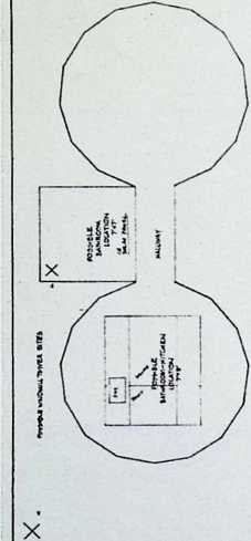
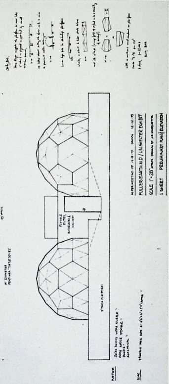
¶ Chapter 29 Bangor-Punta Production Domes Fuller & Sadao, 1971
This mass-producible dwelling was designed in an elegant style comparable to that of such pleasure vehicles as yachts and sport cars. Unlike the Wichita House or the Dymaxion Bathroom, the Bangor-Punta Domes are of extremely refined proportions. They look less like low-cost housing than luxurious beach houses, are set above ground on piers, and are topped by an ornamental roof in a star pattern. Each would have had four closets, two patios, three sofa beds, a kitchen, and a bathroom—all arranged on one floor.
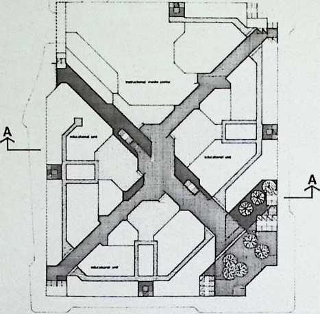
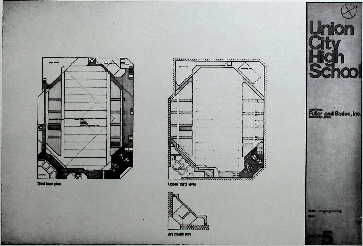
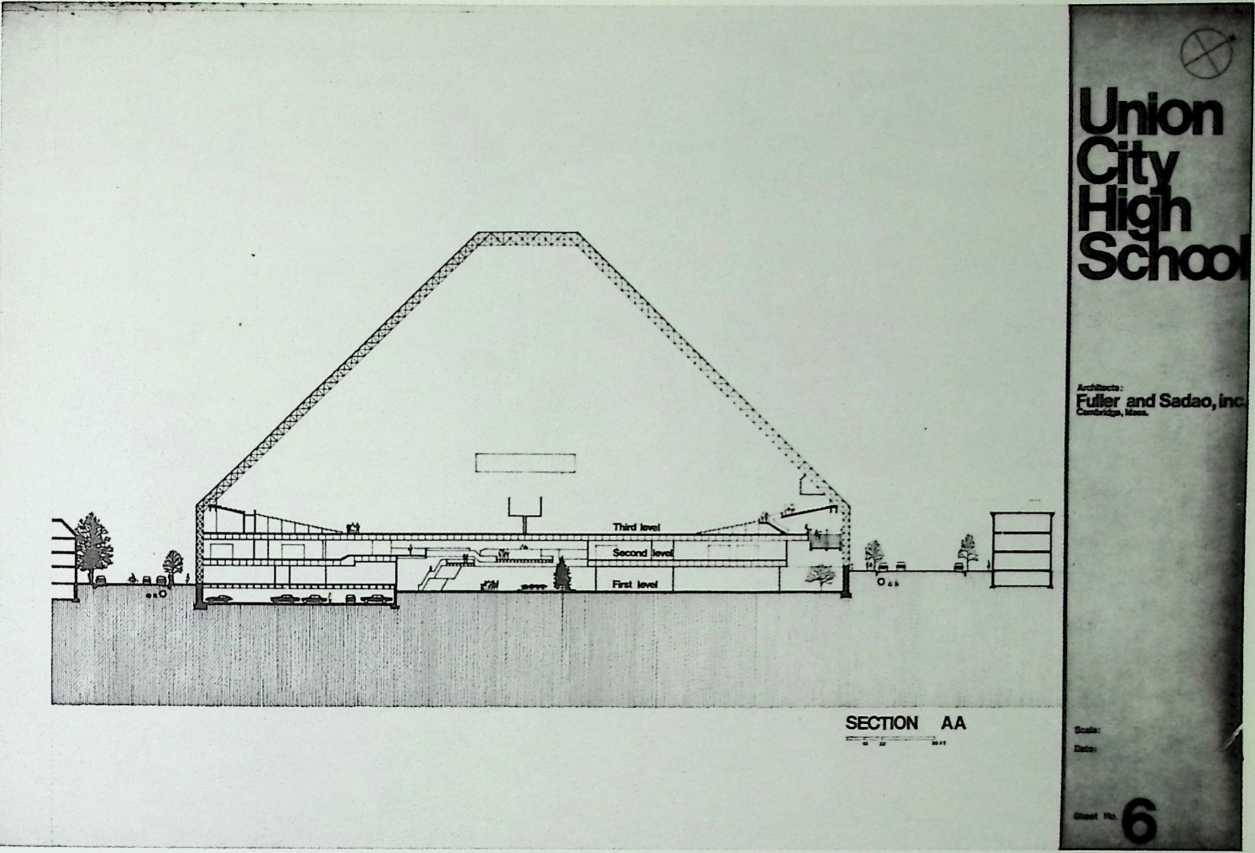
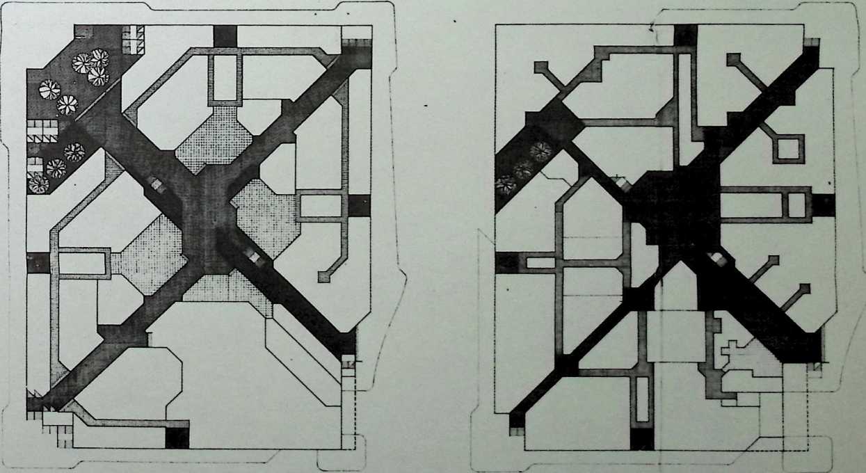
Union City High School, Union City, New Jersey Fuller & Sadao, 1971
The proposal for a new high school in Union City, New Jersey, although not constructed, provided a precedent for several firms that have exploited the glazed truss subsequently. The high school would have had two lower stories of classrooms and offices, and its gymnasium would have occupied the tapered uppermost stories.
24” Street
(LftniGODT)
Second level plan
Architects:
Fuller andSadao.inc.
CcmbrkJgo, Moss.
Erst level plan
Choct No.

SCttroL.
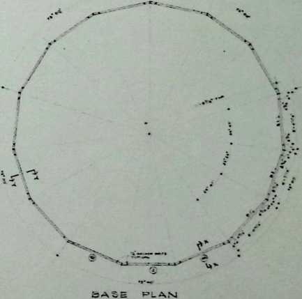
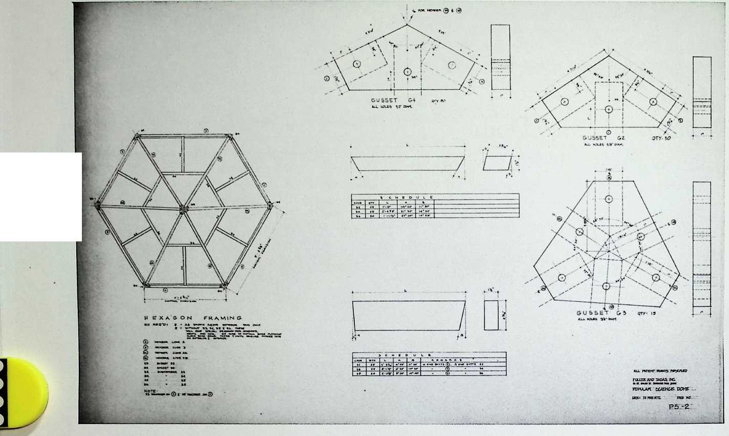
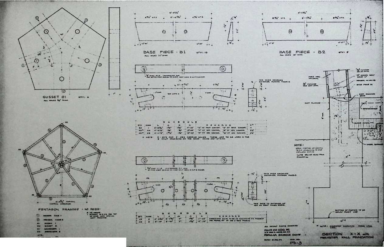
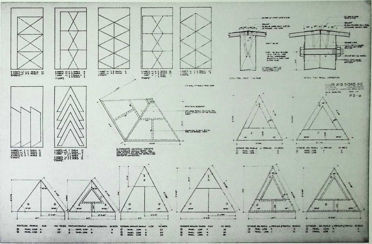
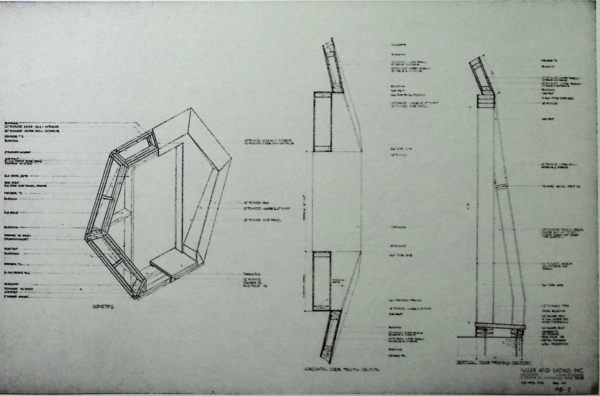
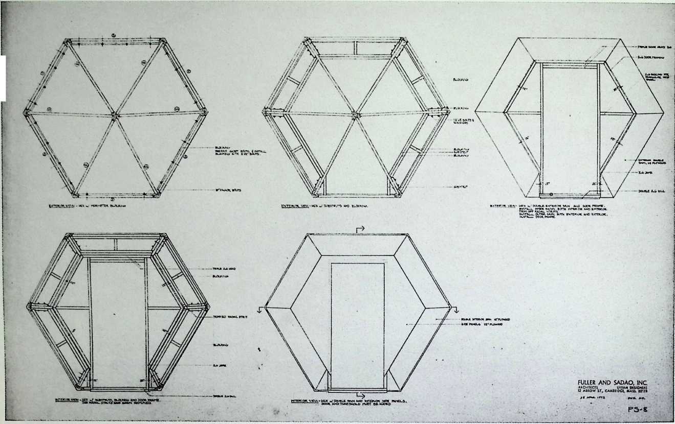
Popular Science Dome Fuller & Sadao, 1972
This dome was designed for mass production and, was simplified in order to promote the idea of the geodesic dome. The framing of two-by-fours and the sheathing of plywood made these structures both inexpensive and relatively easy to construct. Perhaps because of its cost and the interesting arrangement of fenestration and vents, the Popular Science Dome was a great success.
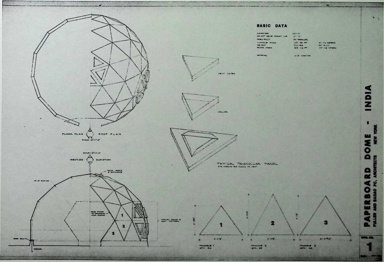
¶ Chapter 30 Paperboard Dome, India Fuller & Sadao, 1972
This paperboard dome was designed during 1972, a time when Fuller was particularly keen on solving the housing problems of the Third World. It is twenty feet in diameter and twelve feet high, weighs 320 pounds, and was fabricated in CCA Dinacor. It is composed of triangular panels, into which the occupant can cut air vents. The dome is raised on a wood sill, and its hexagonal door has a wood frame. Although Dinacor is waterproof, the dome is suited ideally to arid climates.
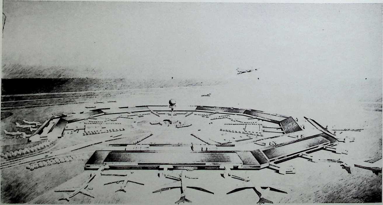
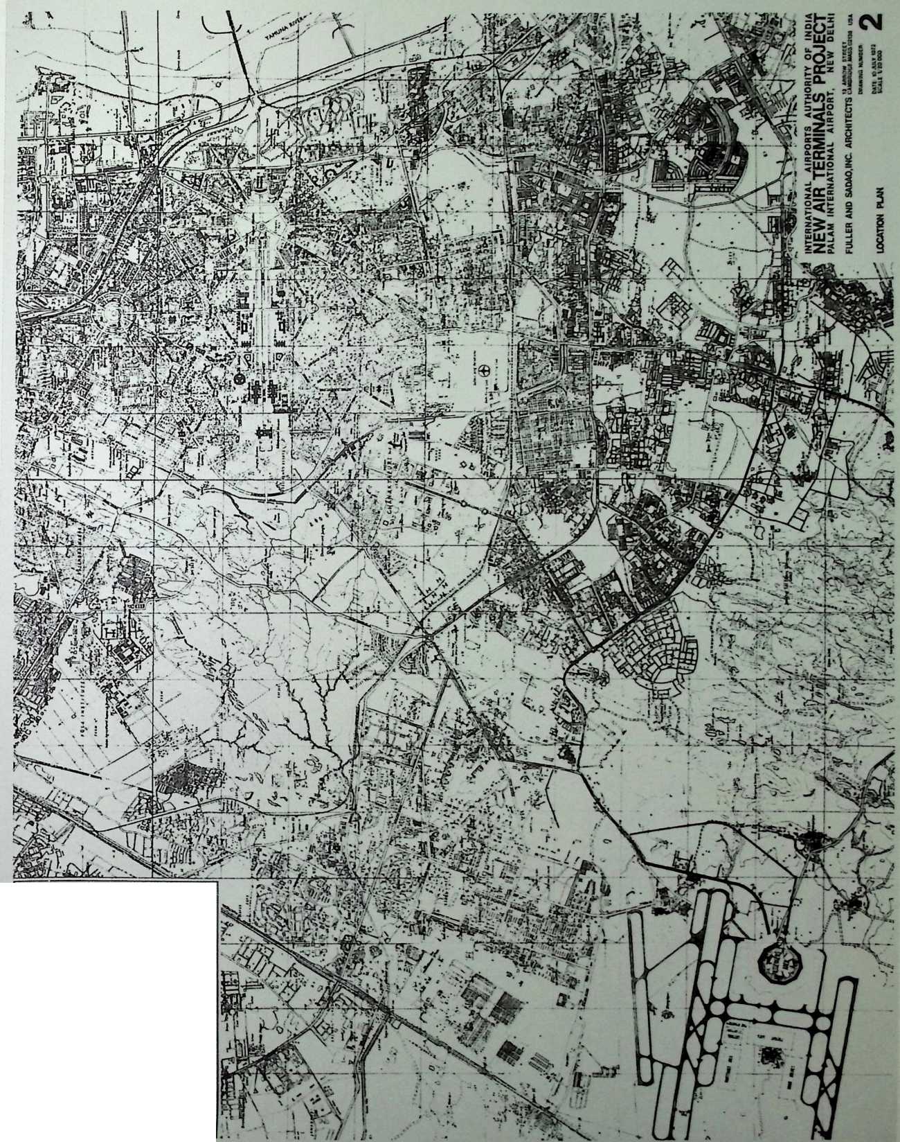
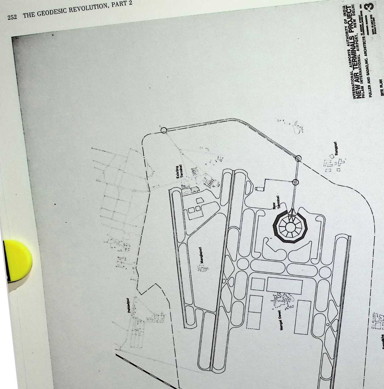
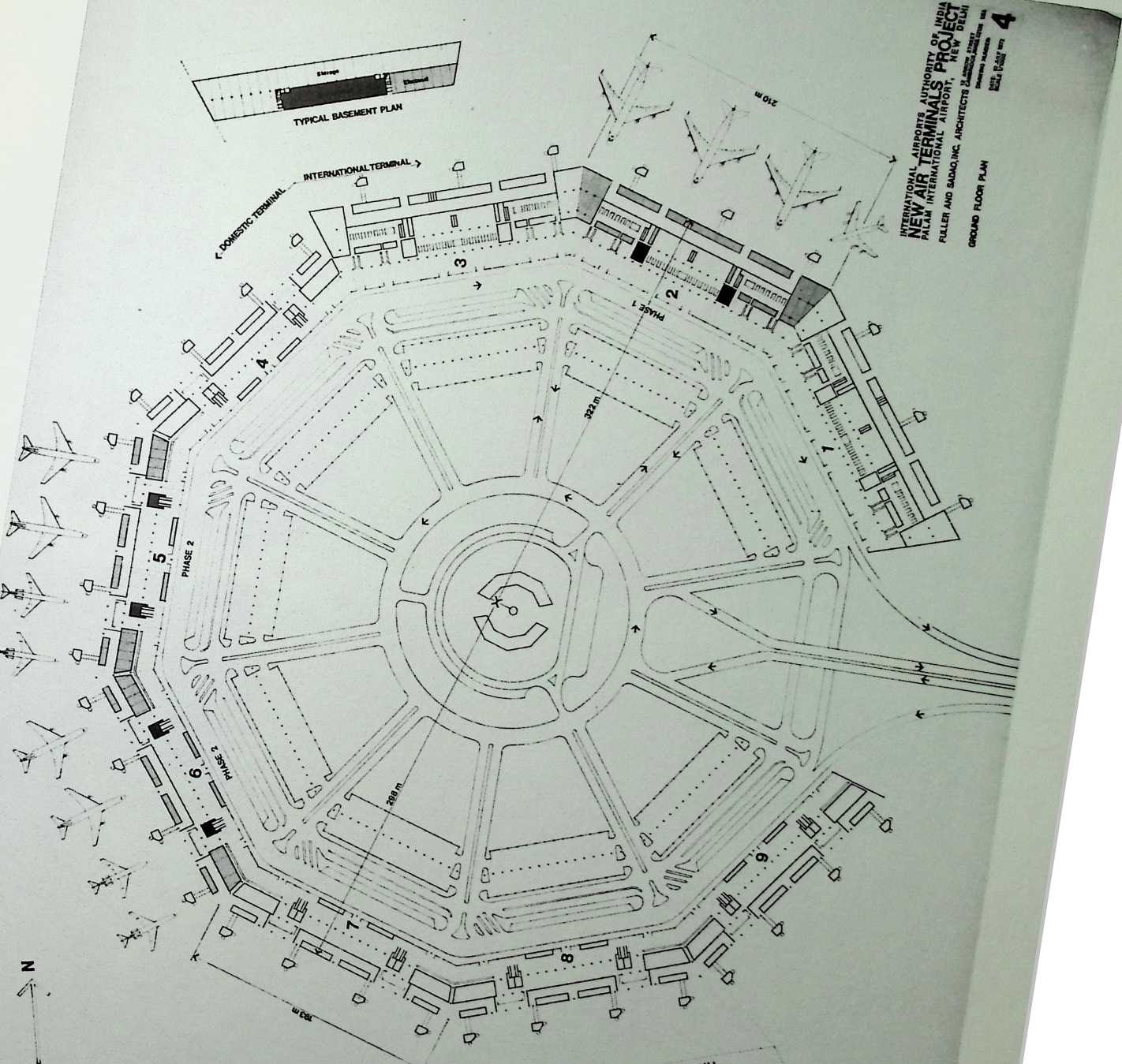
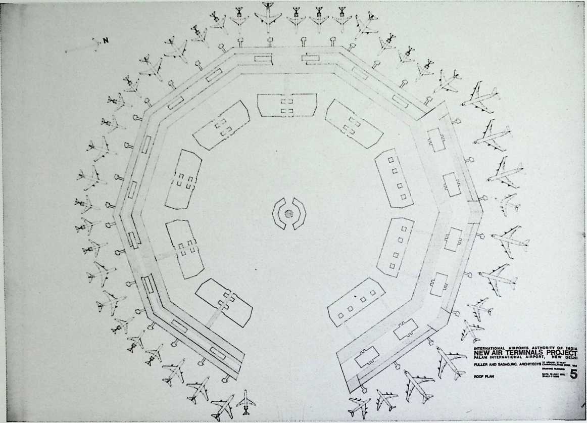
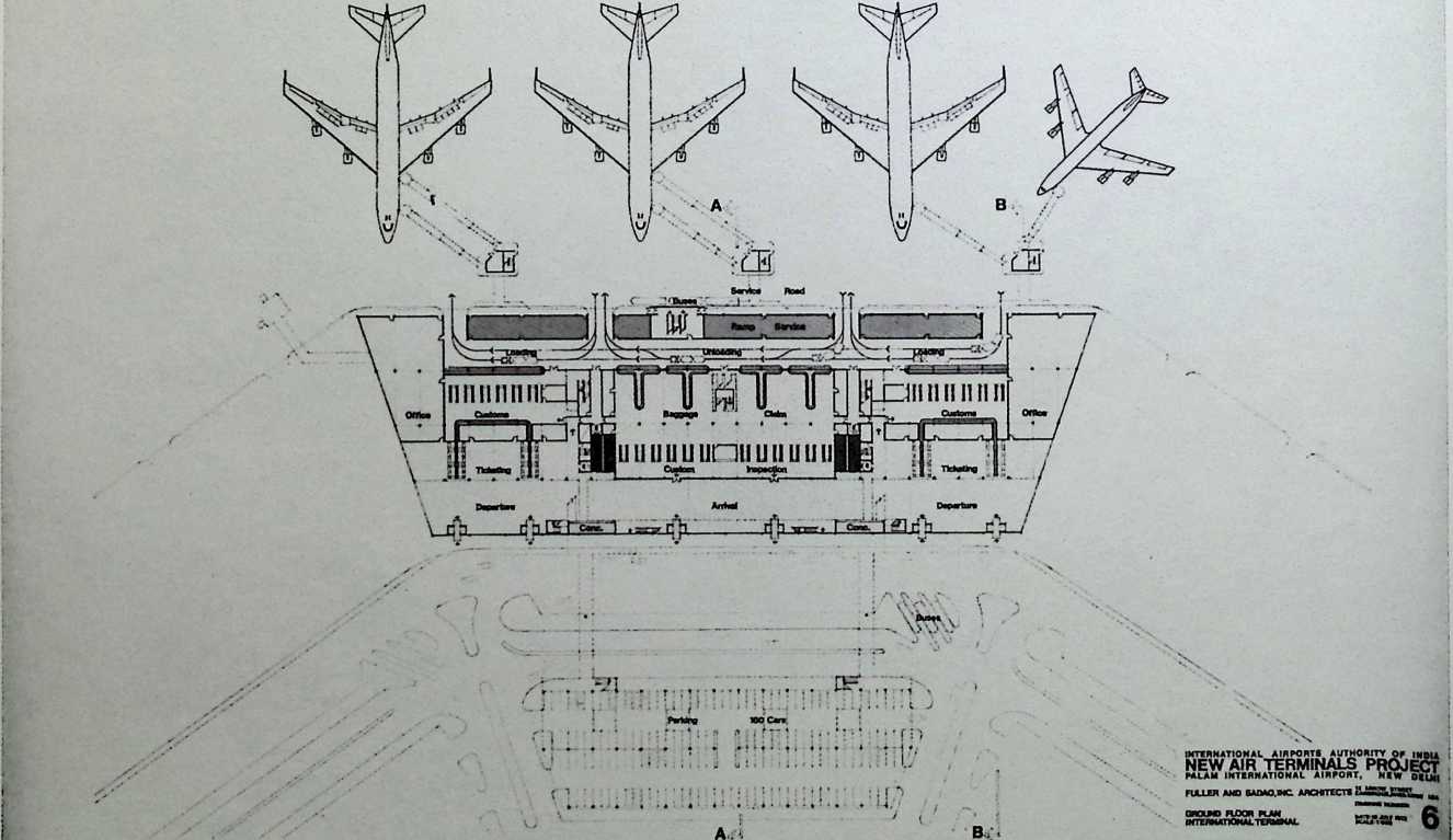
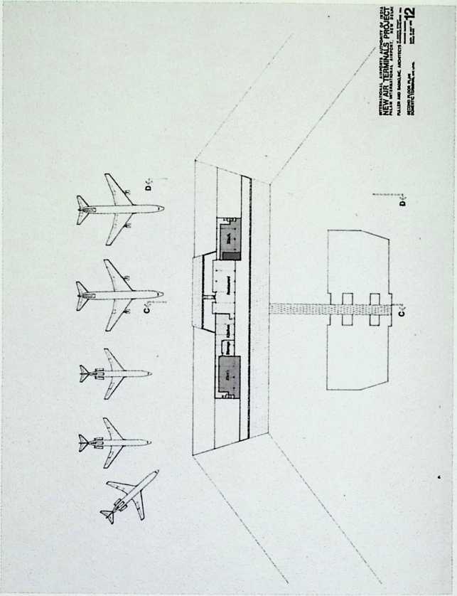
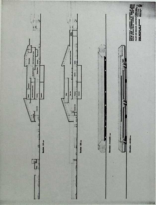
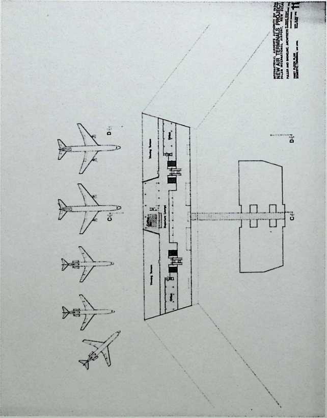
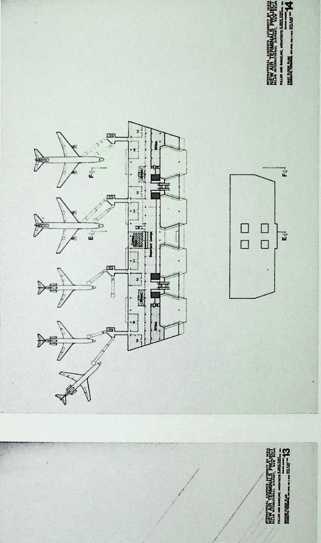
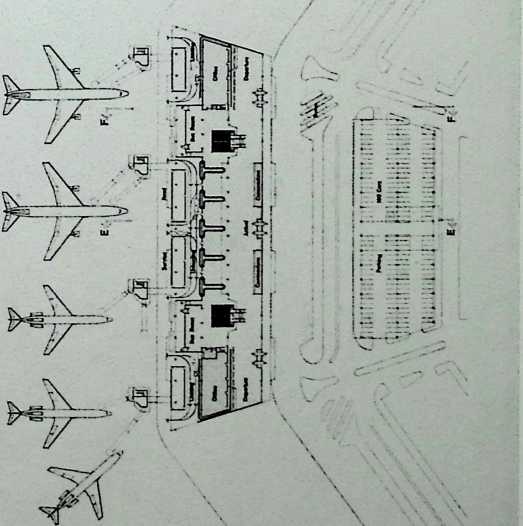
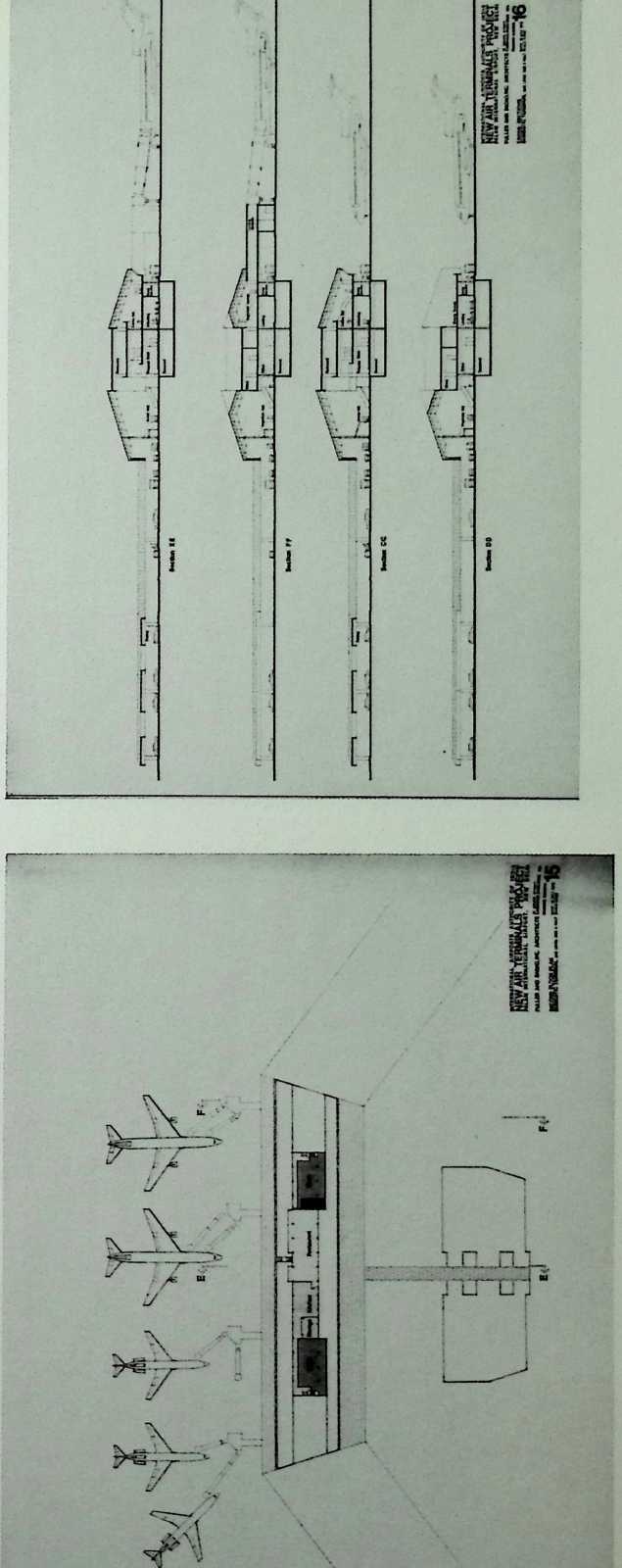
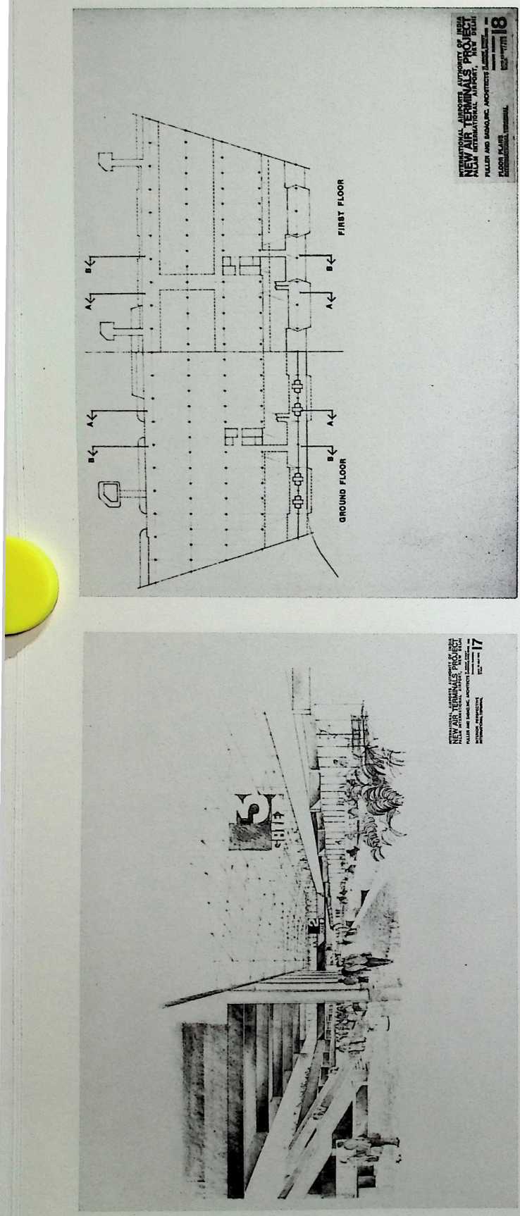
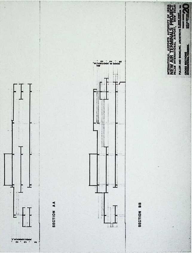
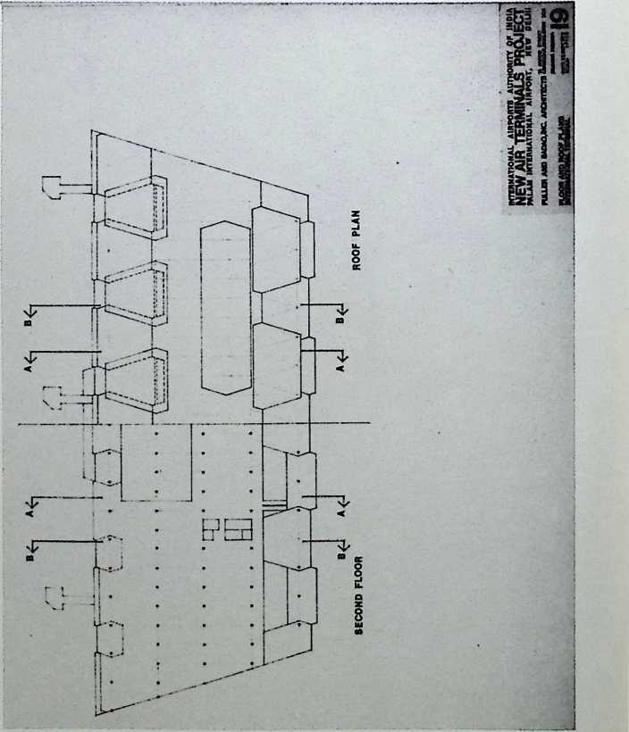
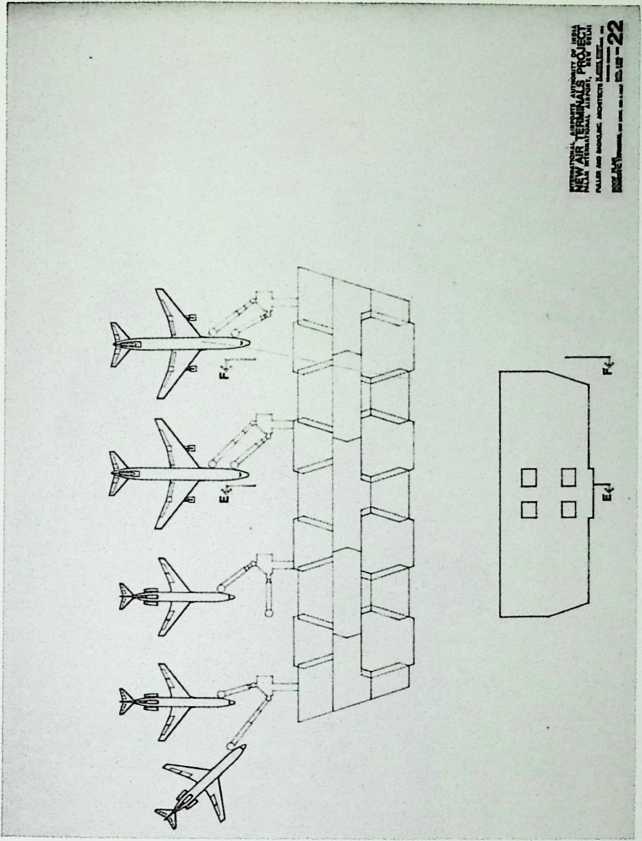
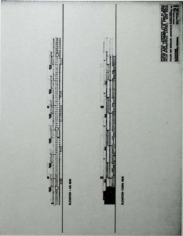
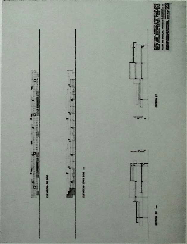
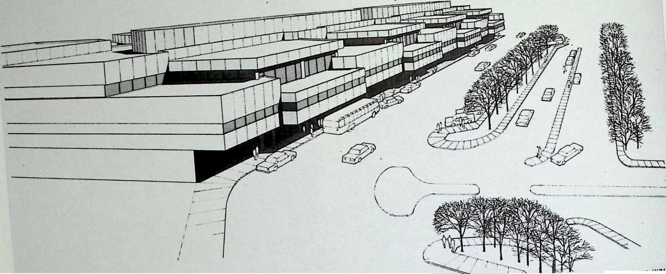
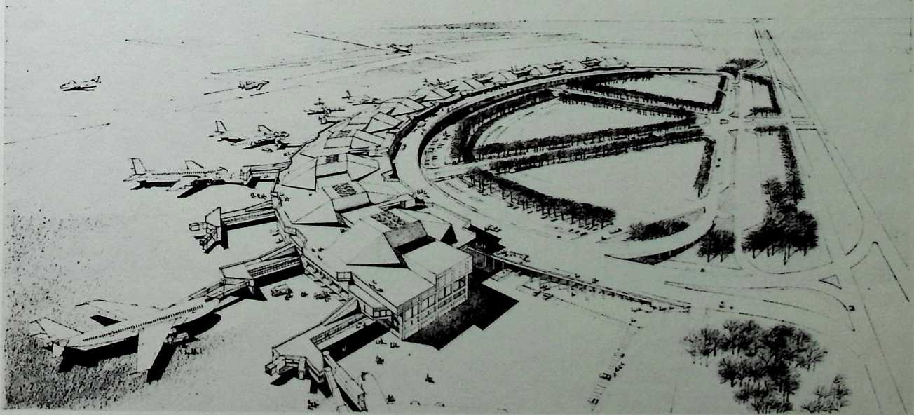
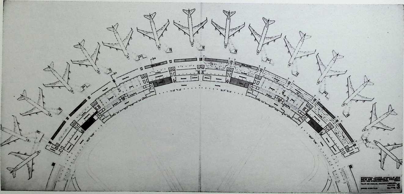
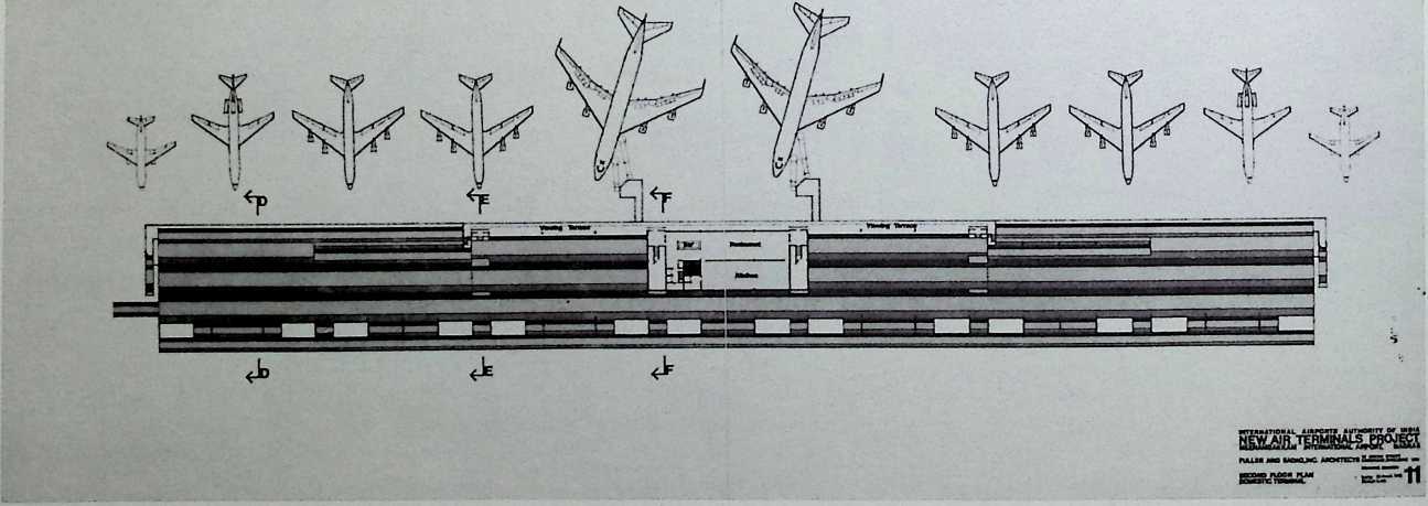
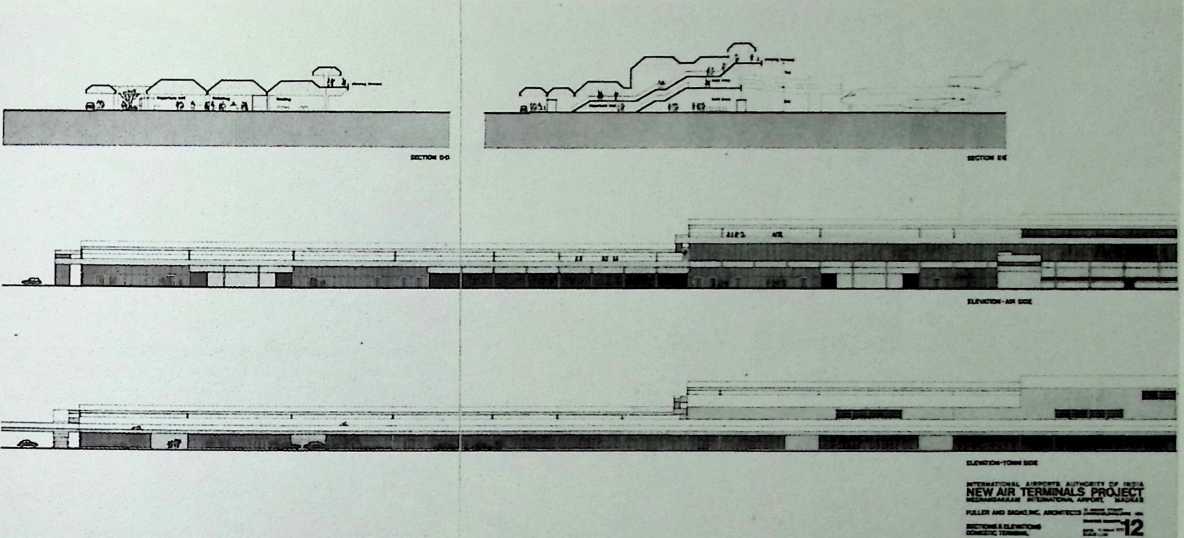
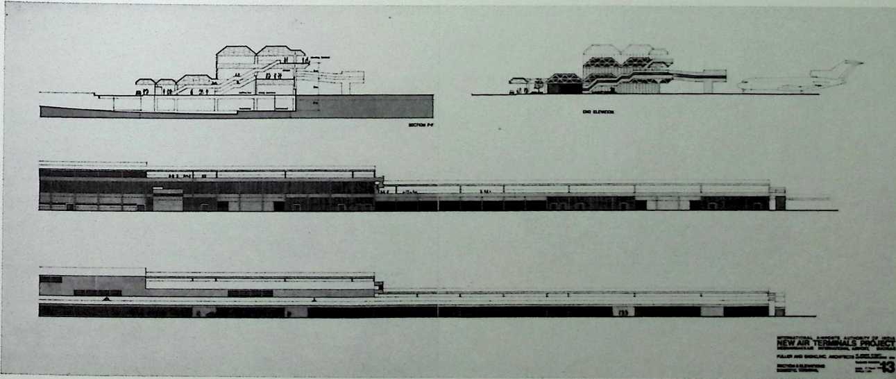
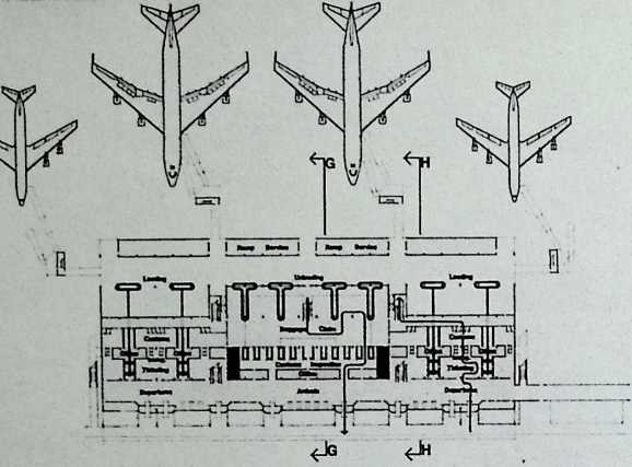
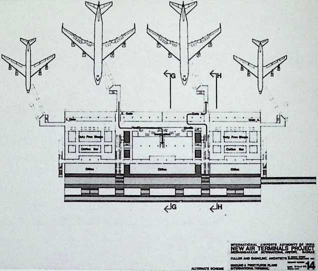
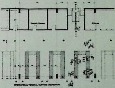
¶ Chapter 31 International Airports for India: Palam in New Delhi Fuller & Sadao, 1972
The Palam Airport for New Delhi is a very large, open decagon, each building of which is composed of glazed trusses. A traffic rotary runs around the center of the decagon, at the center of which is a control tower with a geodesic dome. The planes are serviced on the terminal’s polygonal perimeter.
INTERNATIONAL AIRPORTS AUTHORITY OF INDIA NEW AIR TERMINALS PROJECT PALAM INTERNATIONAL AIRPORT, NEW DELHI
FULLER ANO 8A0A0.INC. AROtfTECTS SmSSuSSw ■*
the
CE0D®'C REVO,
LLT;O.V. part\ 2
253
![]()
![]()
![]()
PALAM INTERNA! I
FULLER AND SADAO.INC. ARCH CTS —
om. fcO
TOVffi.?ALTERMlNAL
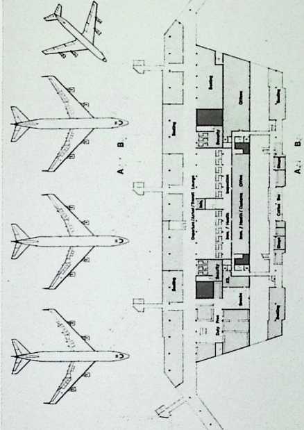
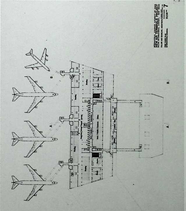
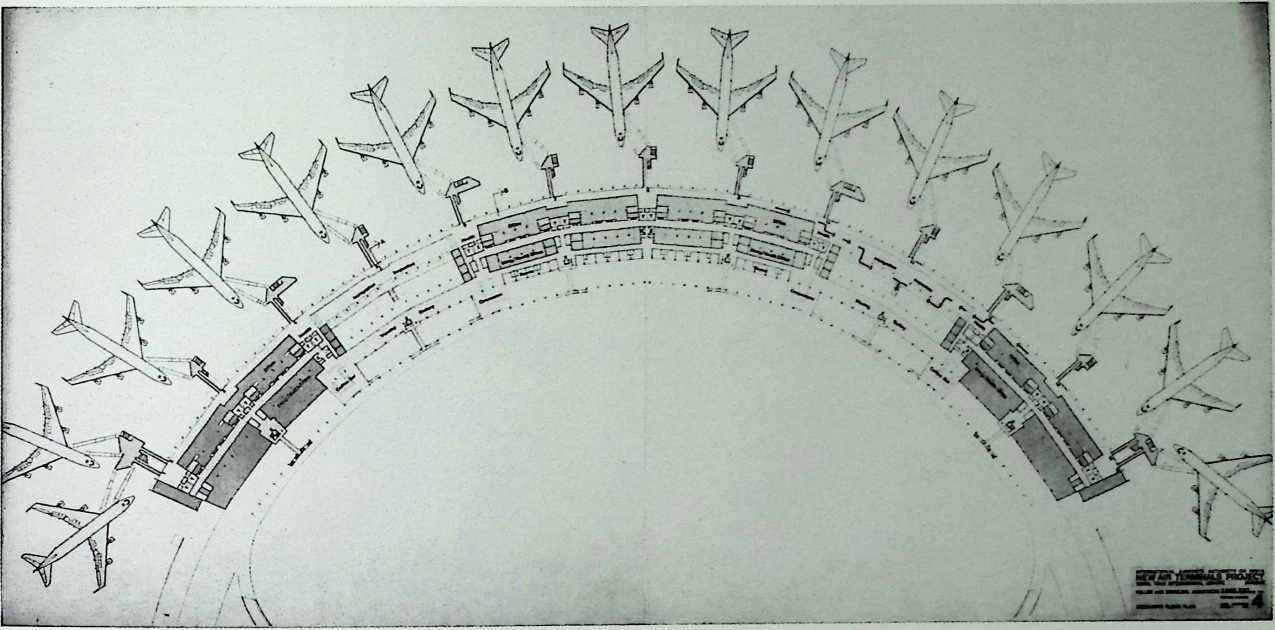
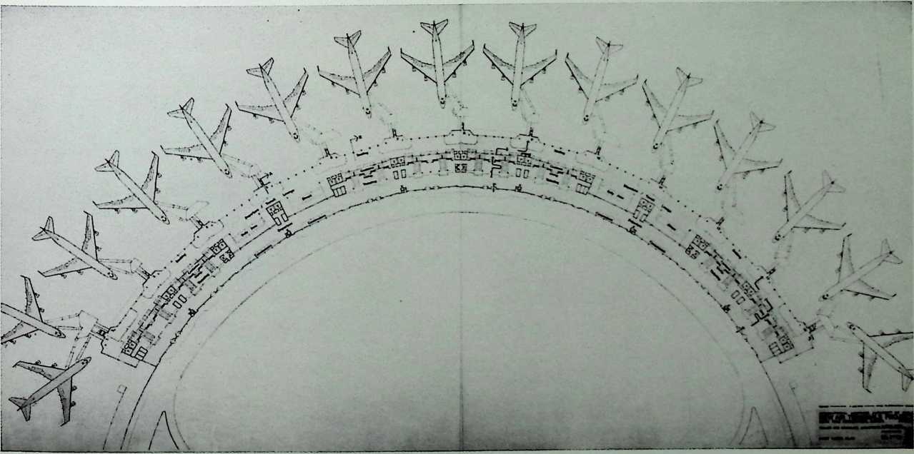
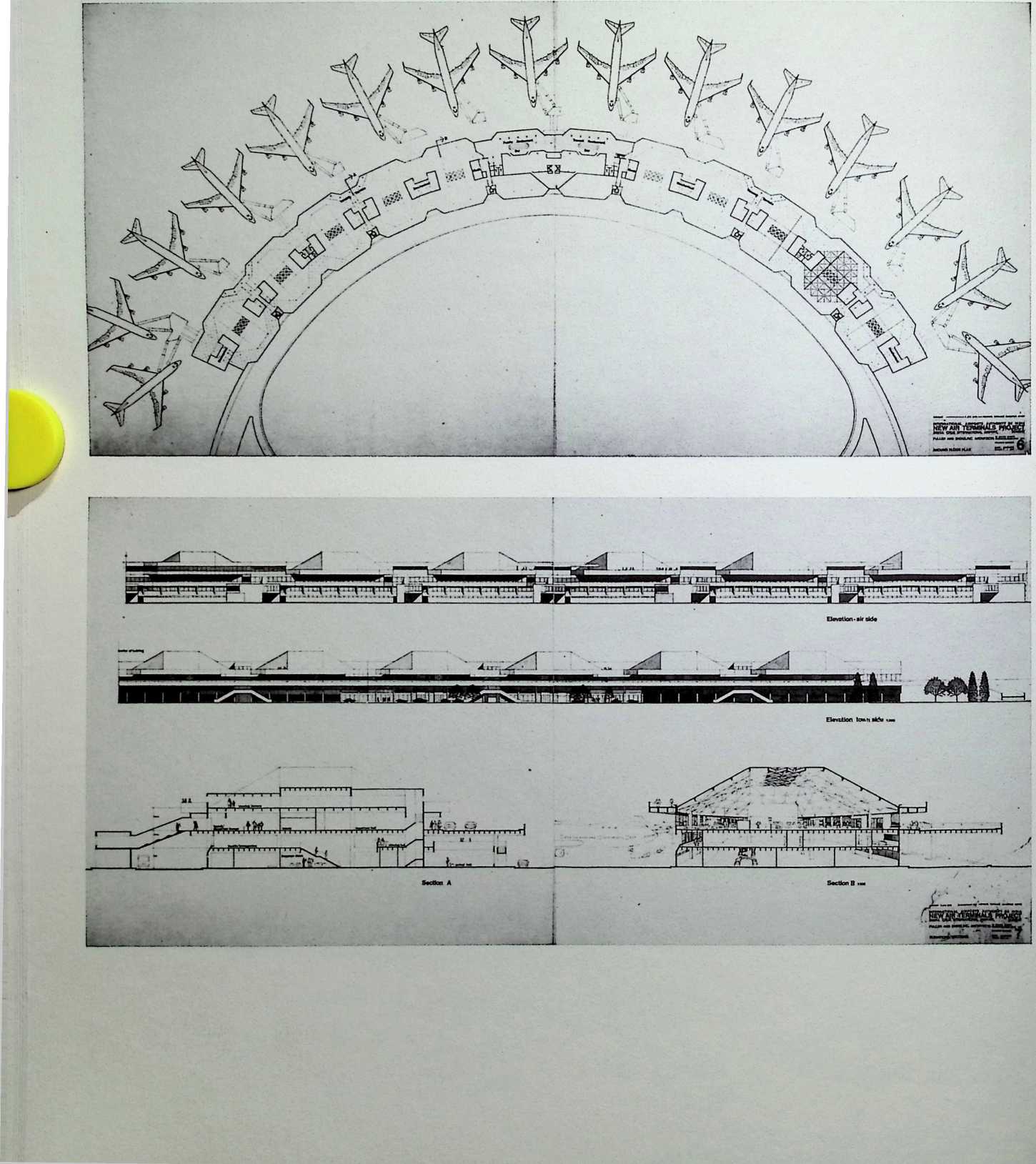
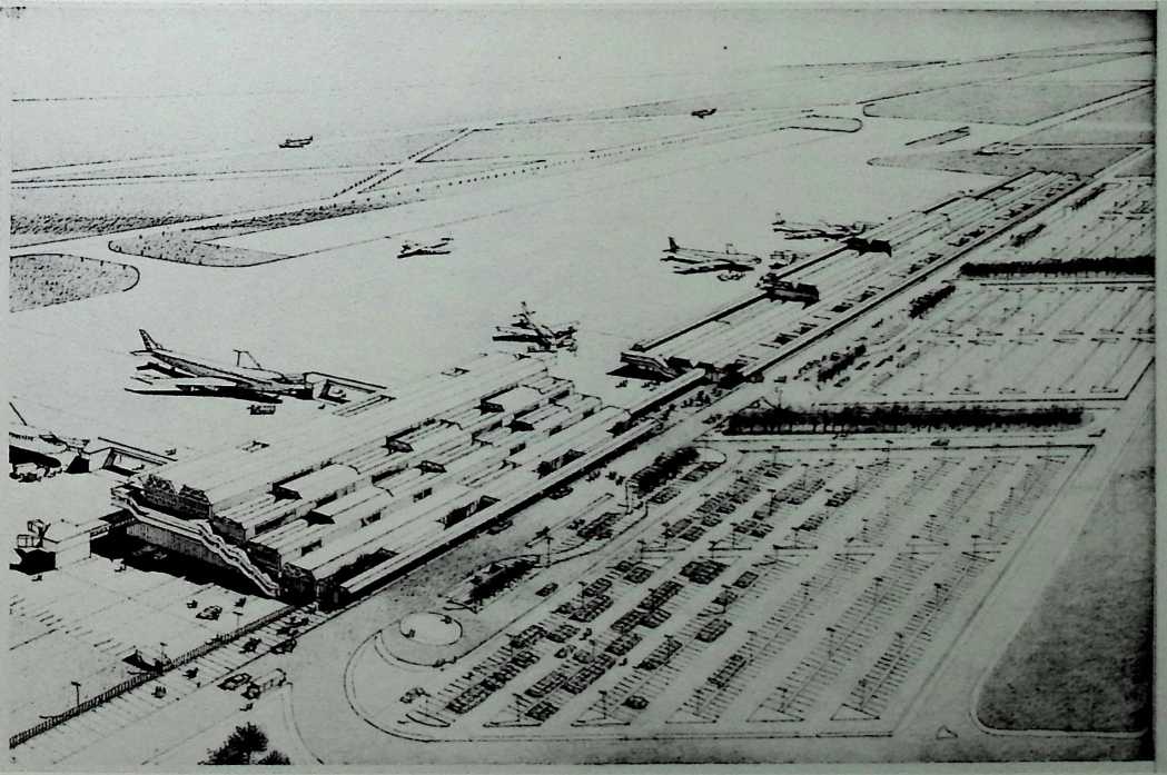
¶ Chapter 32 International Airports for India: Santa Cruz in Bombay Fuller & Sadao, 1972
The design of the Santa Cruz Airport in Bombay is architecturally the most impressive of the Fuller & Sadao designs for airports in India. Its concave plan of twelve octagonal, geodesic concourse vaults combines with the shapes of the attending jet liners to produce an aviatory diadem when viewed from the sky.

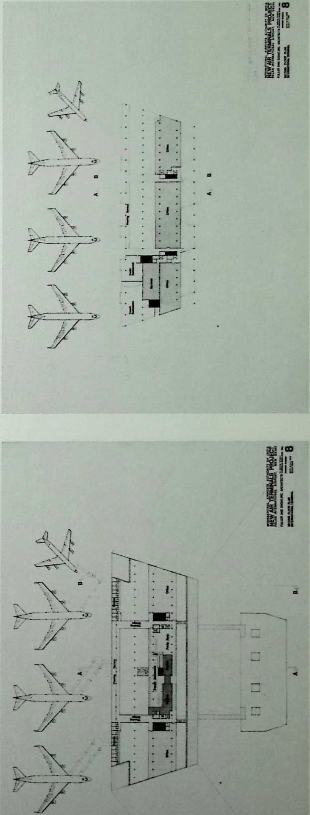
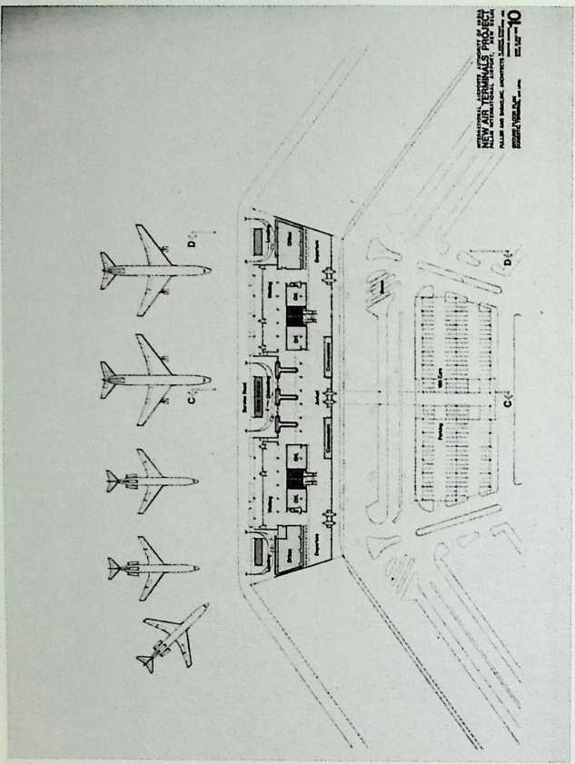
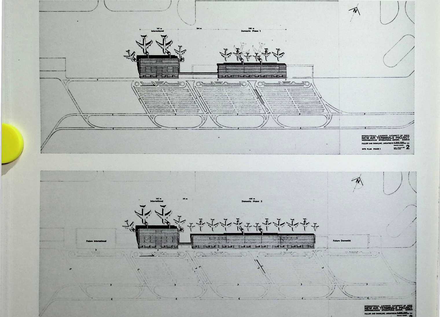
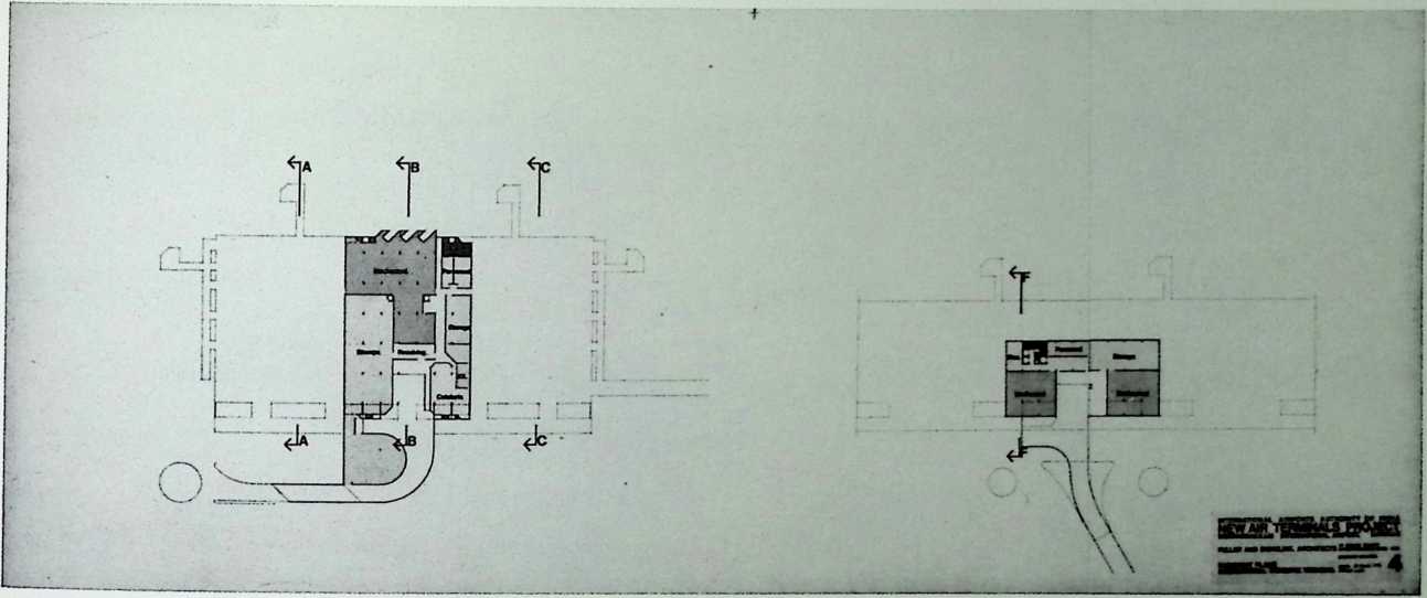
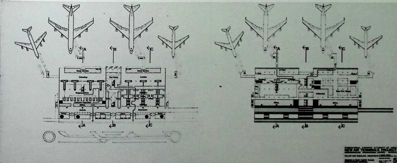
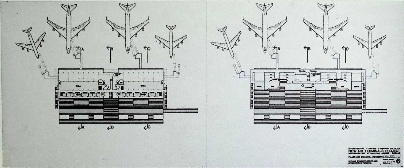
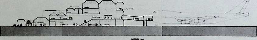
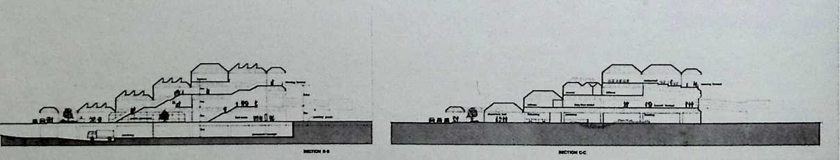
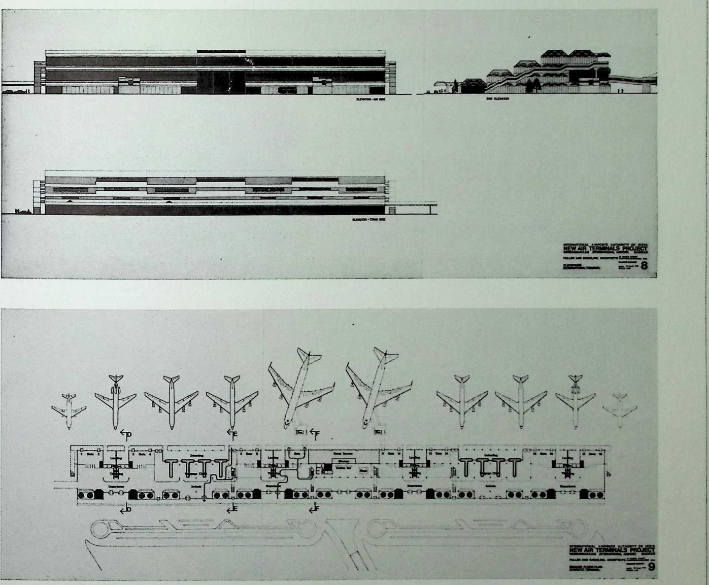
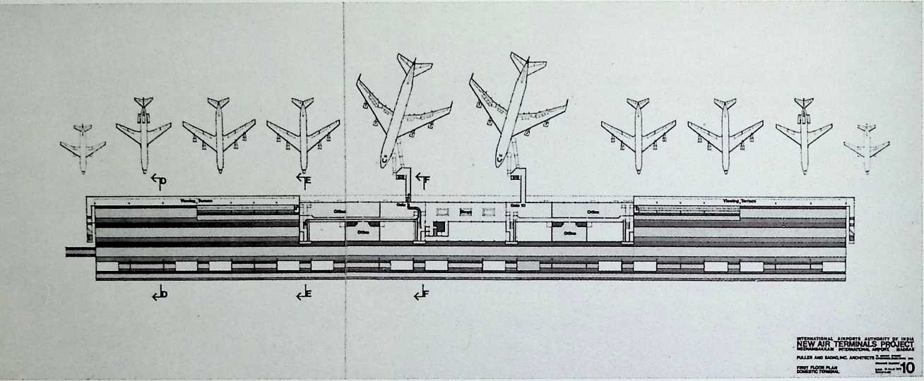
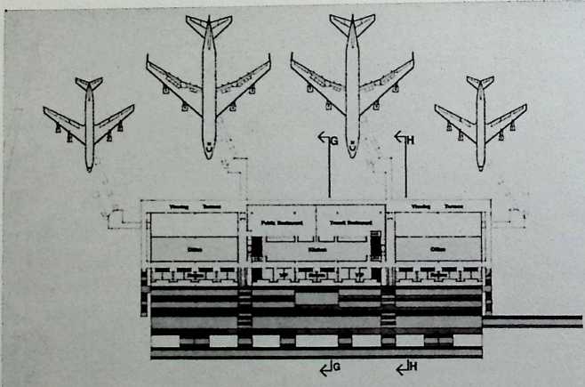
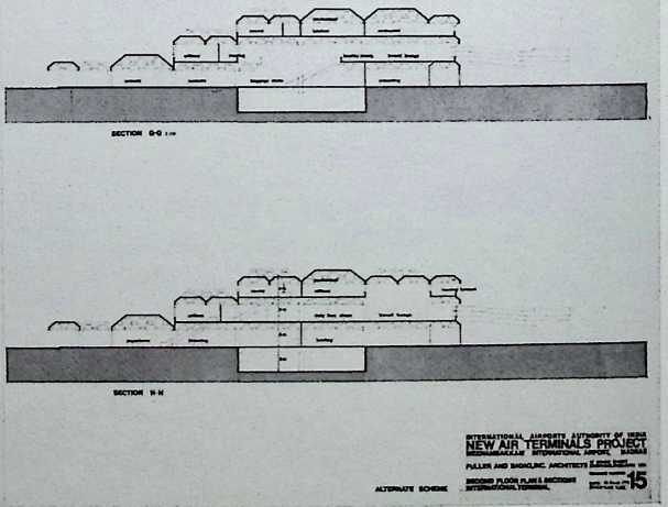
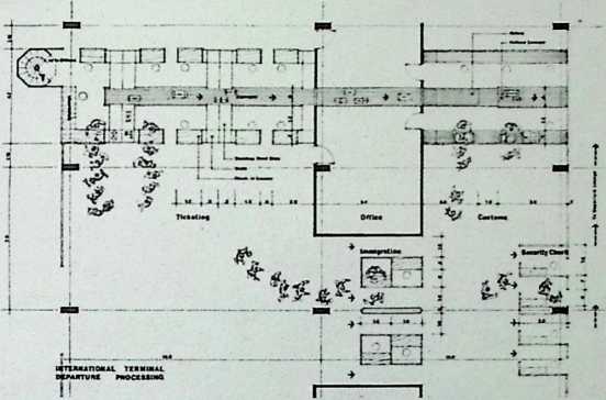
International Airports for India: Meenambakkam in Madras
Fuller & Sadao, 1972
The Meenambakkam Airport in Madras has two small pavilions (three stories each) and was designed to allow visitors to view passengers at every stage of their arrival and departure.
■rmnuncMAi i mm aotmoutv c* iwoia NERTERMALS PROJECT
MC MKIK MOTKH w
— ‘‘ ‘‘ 1
•HKM MMM
KIXM N0 BNMOVC. MKMTKn rusnmw M
SS&3o«M.Toa* BWF 7
![]()
NEWAtfT
an aaax*
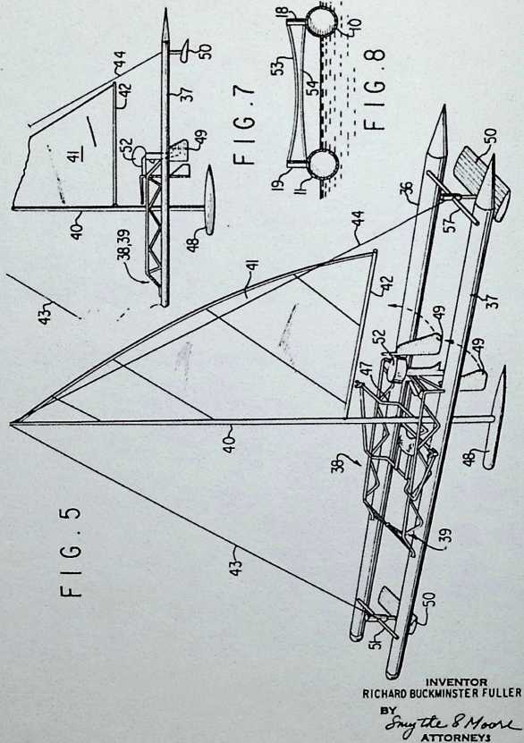
The Spruce (Sailboat) 1973
The Spruce is a sailboat with a spar attached to a geodesic mast with a universal joint.
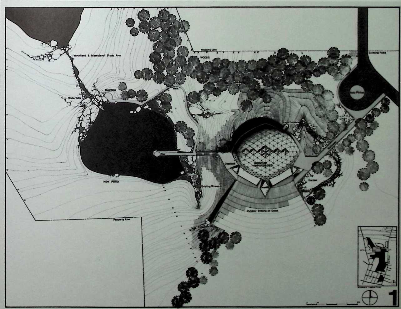
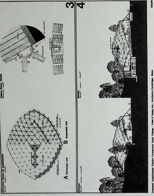
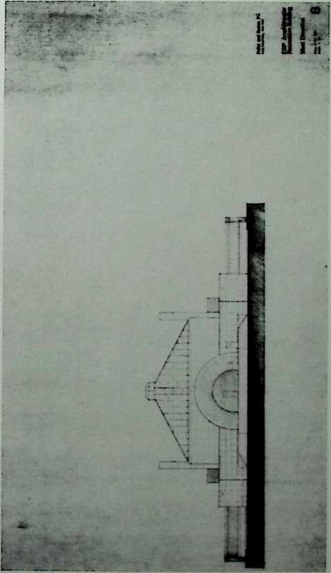
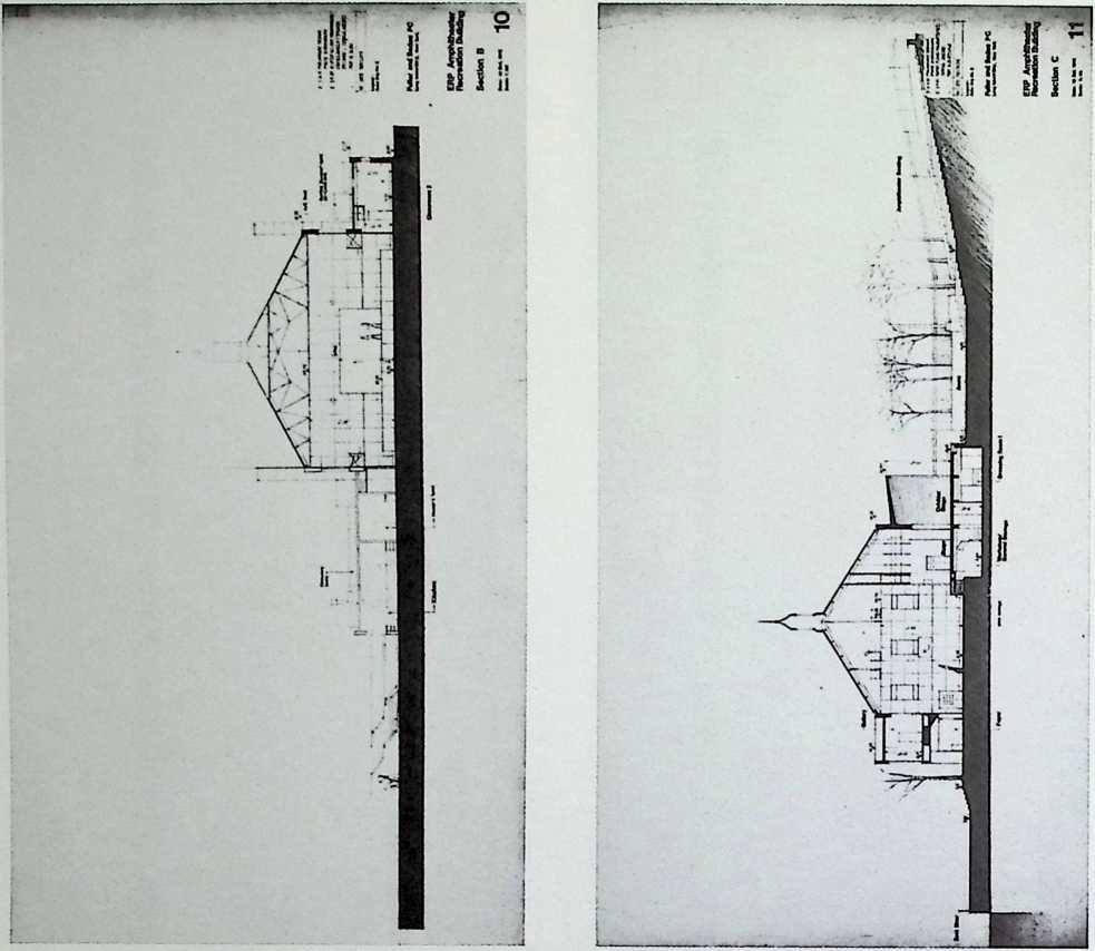
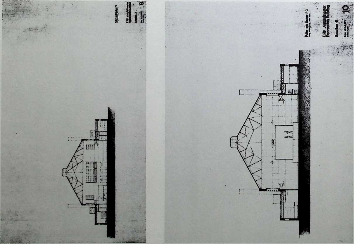
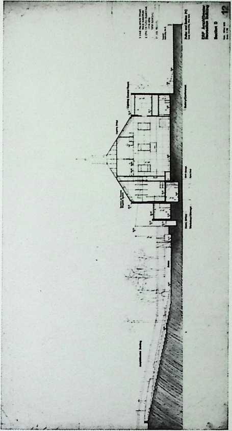
¶ Chapter 33 Eastern Connecticut State College Amphitheater Fuller & Sadao, 1973
Fuller pushed the design of the geodesic dome to its architectural limit in this assembly hall that resembles superficially such striking prototypes as the Ingalls Hockey Rink at Yale University by Eero Saarinan (1959).
Proposed Amphitheater • Eastern Connecticut State College • Fuller & Sadao, Inc., Architects. Cambridge. Mass. Site Plan
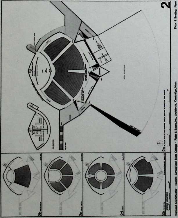
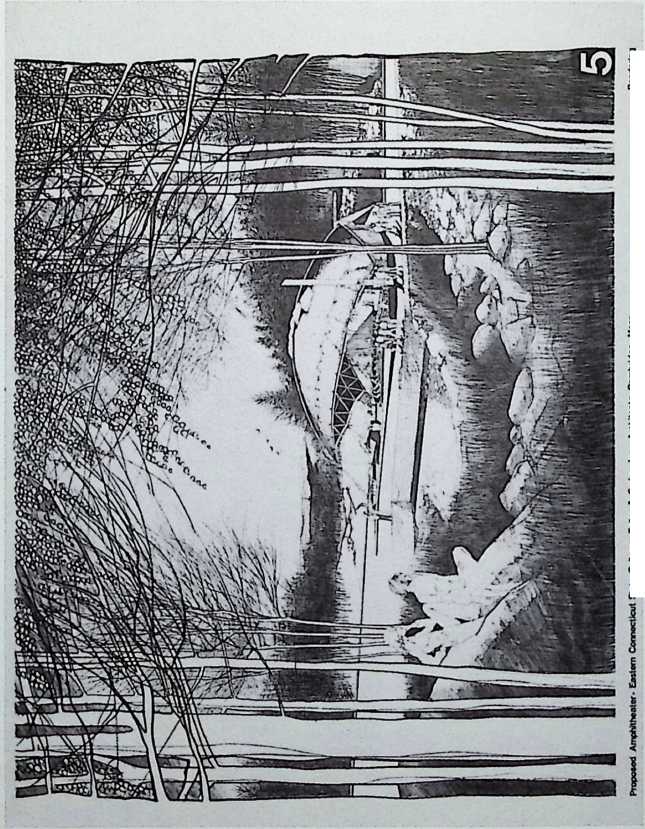
State CoOego • Fuller & Sadao, Inc., Azchilecta, Cambridge, Ma*a. Rendering
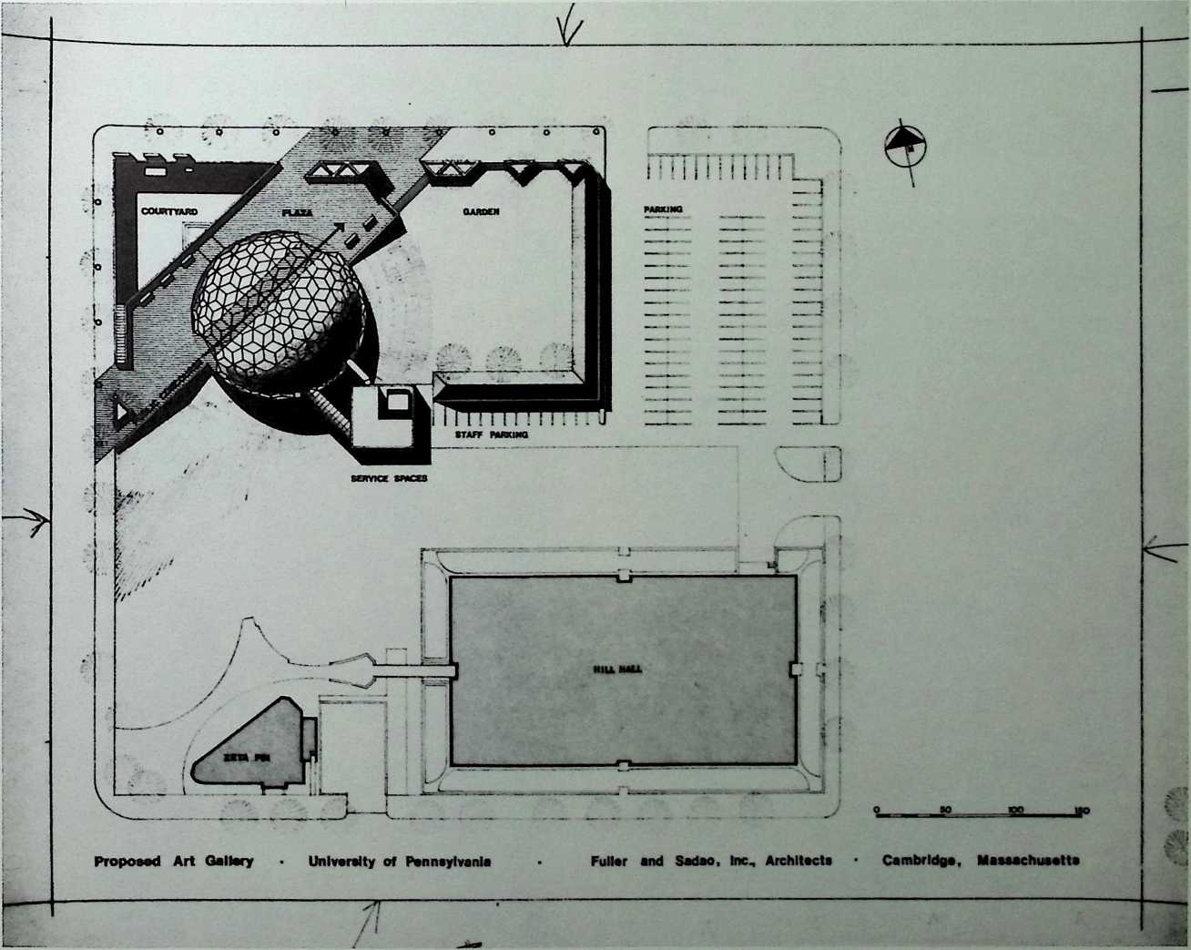
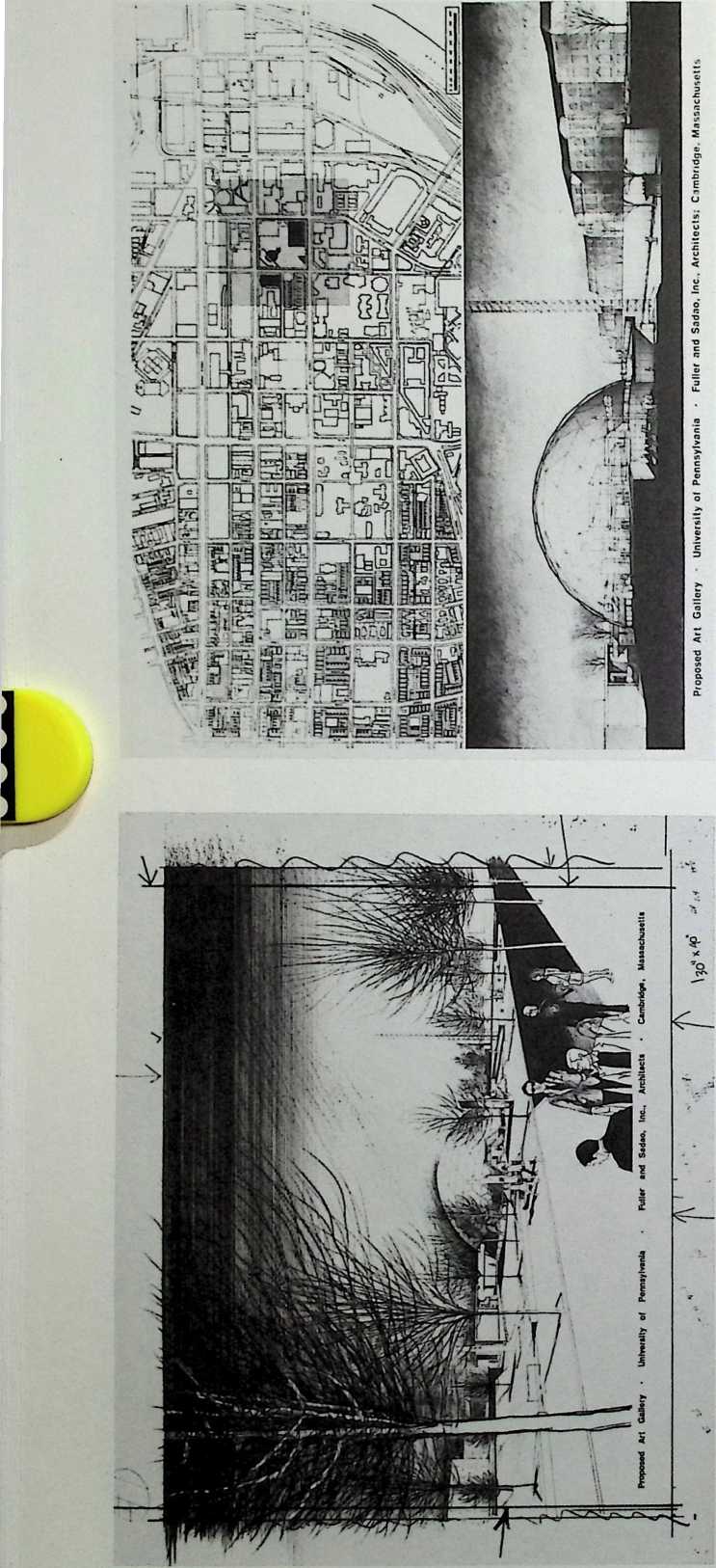
University of geo<eSC ome unfortunately, was never realized.
¶ Chapter 34 Pennsylvania Art Gallery Fuller & Sadao, 1973
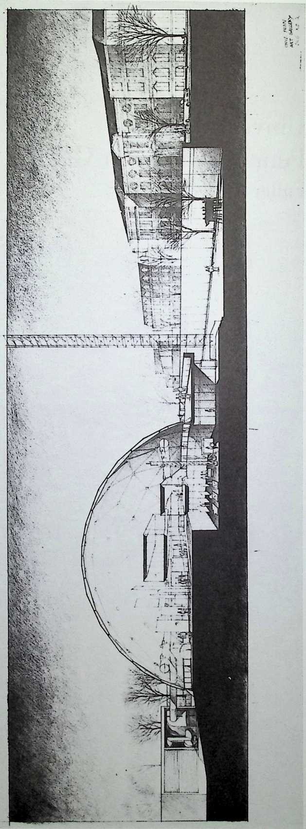
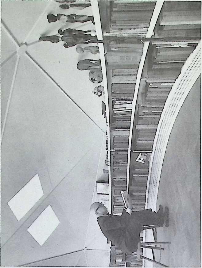
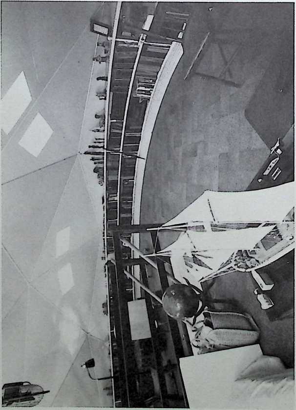
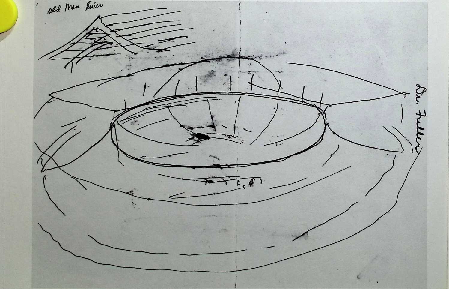
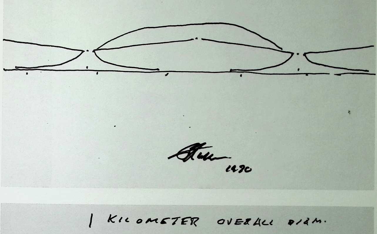
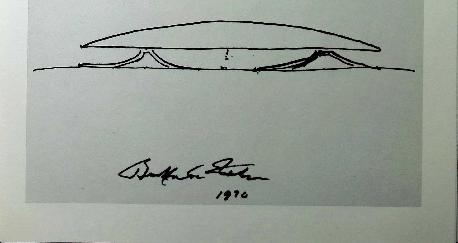
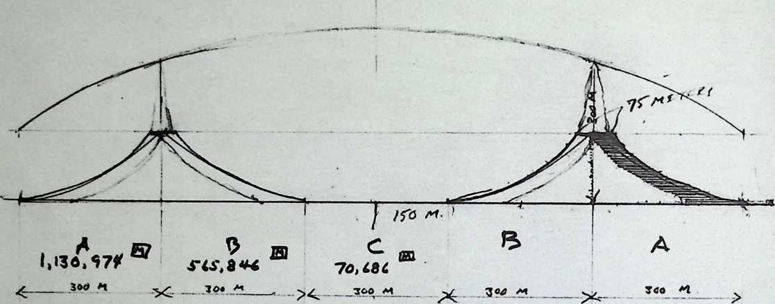
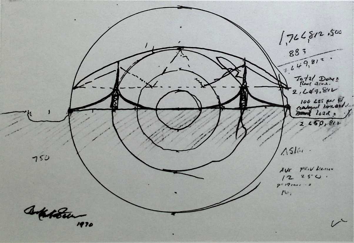
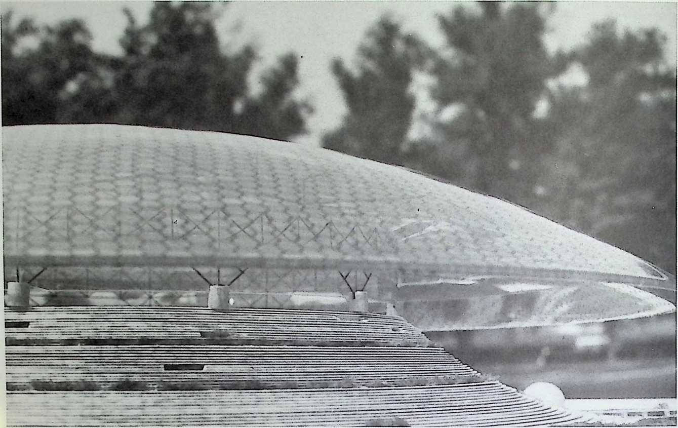
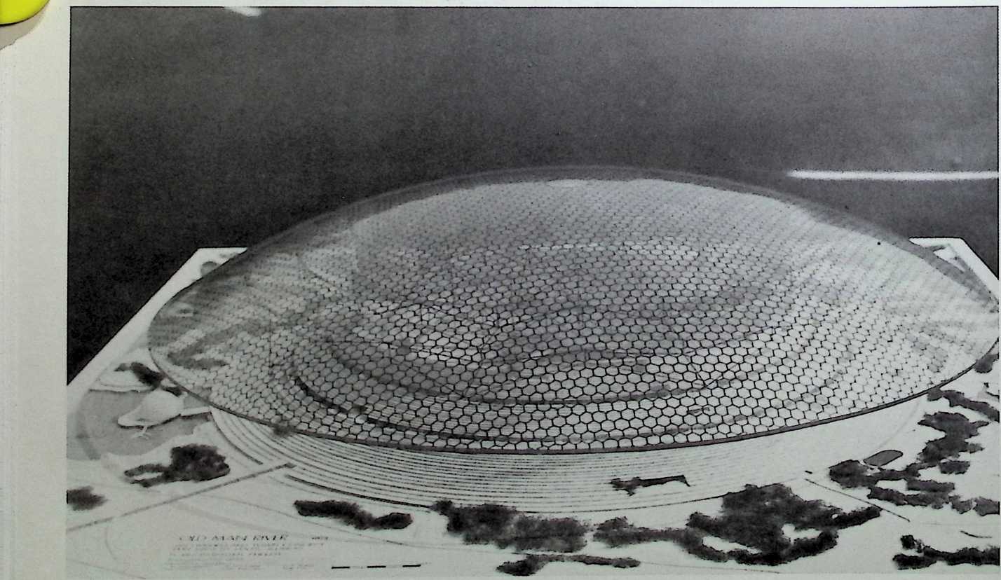
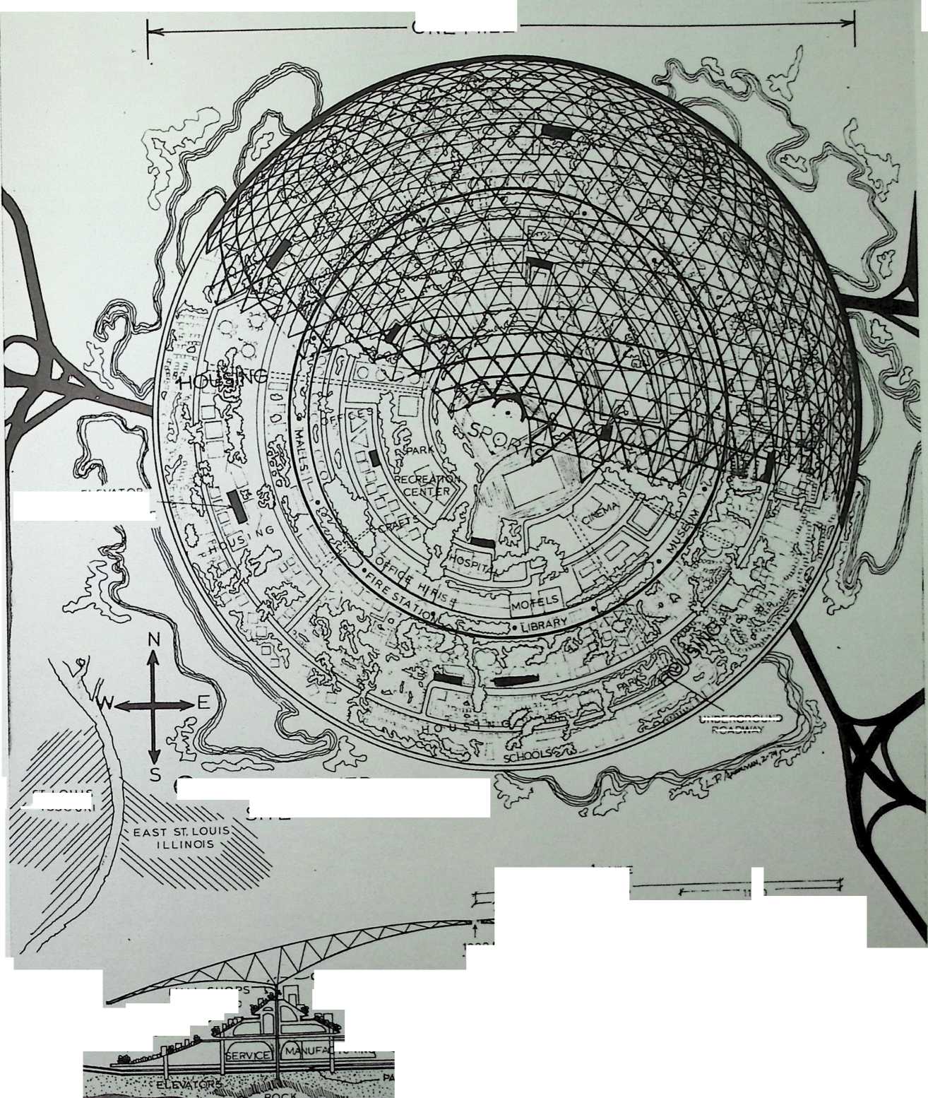
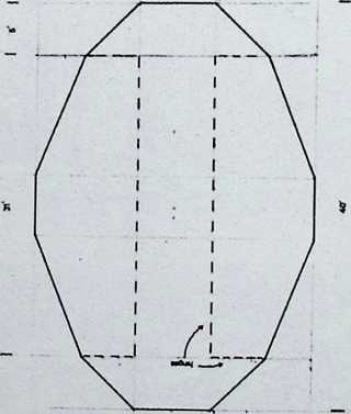
¶ Chapter 35 Old Man River: An Umbrellaed Town Concept for East Saint Louis, Illinois 1970–1974
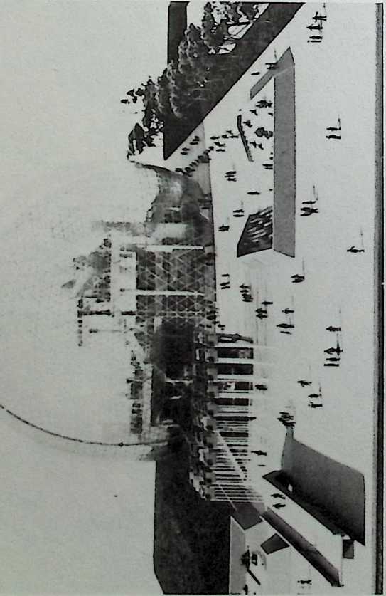
Old Man River is Fuller’s most ambitious planned city organized under a single roof. It is a circular town with a protective, domical umbrella 2,200 feet in diameter and 500 feet above the ground at its edge. This structure, which is like a vast and stiffened velarium, is supported on beams driven into the rim of a reinforced crater, on either side of which are arranged the buildings of the town.
¶ Chapter 36 Old Man River, Sketches 1970–1971
Old Man River, Finished Project 1974
AN UMBRELLAED TOWN CONCEPT FOR EAST ST. LOUIS. ILLINOIS
OLD MAN RIVER )Sro
R. BUCKMINSTER FULLER
DESIGN DEVEIOPMENT GROUP WASHINGTON UNIVERSITY
J W fITZGIBBON LEl-HOO MAK C P WANG
CHAI-HSU IU PING-PING HSU ISA’ CHi
ONE MILE
1000 ft.
BRARY, MUSEUM
A
STADIUM
'.ENTRANCE
ROCK
KING-T
450 'eat
JfMiLE
-RADIUS
100 'eet
ELEVATORS
SHOPS.-, [rti
BUS TRANSIT CENTER
HOUSING
HOUS'NG
RING ROAD THRU ROAD HOUSING PARKS
COMMUNITY, F|R£\
MAJOR shopping A STATlOf
COMMERCIAL AR~a— ■
UNDERGROUND
ROADWAY
PARK NG
ACCESS
ELEVATOR,
TRANSIT
CONCOURSE
ST LOU IS
MISSOURI
© OLD MAN RIVER
SITE
CLUBS
NIGHT CLUBS
CINEMA
MOTEL
TURIN!
R £S
■ PARKING1.
![]()
![]()
![]()
![]()
OLD MAN RIVER-AN UMBRELLAED TOWN CONCEPT FOR EAST ST. LOUIS, ILLINOIS
|
||
R> BUCKMINSTER FULLER
WASHINGTONCjNIv’ERSTTY SCHOOL OF
ARCHITECTURE - FEB 1974
Penang Urban Center, Penang, Malaysia Fuller & Sadao, 1974
Fuller and Sadao developed the concept of the sphere above a rectangular volume (see the Campus Religious Center, Southern Illinois University, 1969) for this island state.
fuuf /: t c nc
![]()
BENO ANGLES COUNTS
The Sailor Cat (Catamaran) 1974
The Sailor Cat combines the stability of the earlier rowing needles patent, with the power and maneuverability of a sailboat.
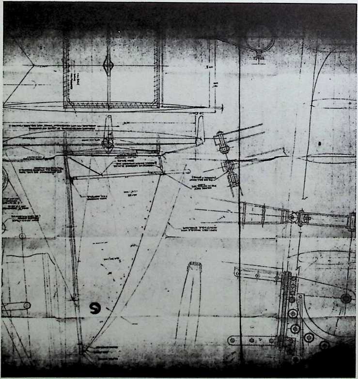
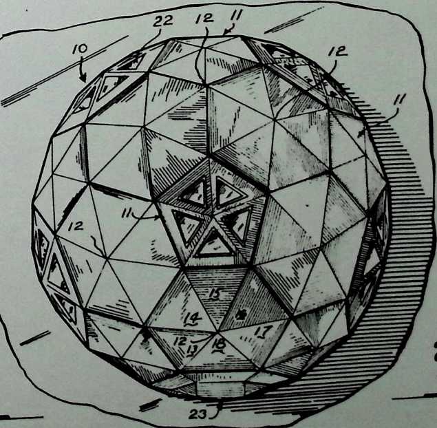
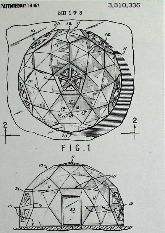
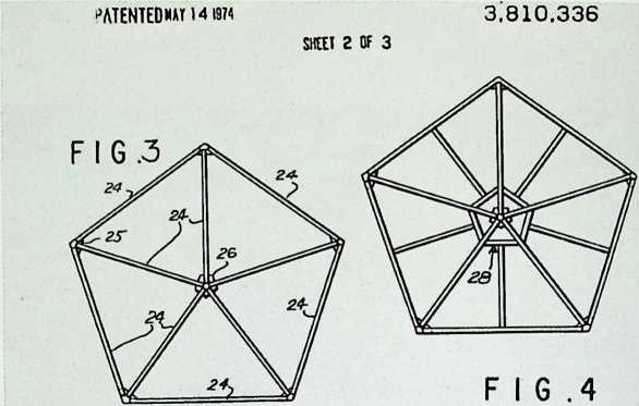
Hexa-Pent Patent
5/14/74
Uunited States Patent i«9j
Sadao
Shoji Sadao designed this small geodesic dome for mass production as low-cost housing. It utilizes hexagonal and pentagonal panels, some of which have transparent panes of plexiglass.
mi 3,810,336
145) May 14, 1974
[54] GEODESIC PENTAGON AND HEXAGON STRUCTURE
[75] Inventor: Shoji Sadao, Boston, Mass.
[73] Assignee: Fuller & Sadao, Incorporated, Cambridge, Mass.
D217.76O 6/1970 Critchlow 52/81 UX
3,114,176 12/1963 Miller 52/81
3.530,621 9/1970 Rutzebeck 52/81
OTHER PUBLICATIONS
Domebook 2, May 1971, pages 14, 25. 31.
22] Filed: May 9, 1972
21] Appl. No.: 251,803
52] U.S. Ci 52/81
51 ] Int. Cl E04b 1/32
58 ] Field of Search 52/80, 81, DIG. 10
56] References Cited
UNITED STATES PATENTS
1.918.992 12/1959 Gelsavage 52/81
Primary Examiner—Henry C. Sutherland Assistant Examiner— Henry Raduazo Attorney, Agent, or Firm—Smythe & Moore
[57] ABSTRACT
A geodesic-type dome structure having the structural elements connected in a pattern of great circle arcs and lesser circle arcs in a three-way grid defining isosceles triangles and including hexagon and pentagon modules.
5 Claims, 7 Drawing Figures
F I G. 2
?ATENTEOM*t 14 ig?s
3.810,336
SHUT 3 OF 3
Floatable Breakwater
Patent
2/4/75
The floatable breakwater is a cylinder floated by tubes twenty feet in diameter and anchored at both ends. It serves to diffuse the energy of approaching waves so that the shore can be developed into a harbor.
(ill 3,863,455
[45] Feb. 4, 1975
United States Patent
Fuller
[54] FLOATABLE BREAKWATER
[76] Inventor: Richard Buckminster Fuller, 200
Locust St., Philadelphia, Pa. 19106
[22] Filed: Dec. 10, 1973
[21] Appl. No : 423,006
[52] U.S. Cl 61/5
[51] Int. Cl E02b 3/04
|5X| Field of Search 61/1 F, 5; 114/.5; 9/8 R
| 561 References Cited
UNITED STATES PATENTS
3,237,414 3/1966 Straub et al 61/5
3,357,192 12/1967 Hibarger 61/5
3,576,108 4/1971 Rowland 61/1 F
3,755,829 9/1973 Walklet 1I4/.5FUX
3,788,254 1/1974 Sheil I14/.5F
Primary Examiner—Paul R. Gilliam Assistant Examiner—David H. Corbin Attorney, Agent, or Firm—Smythe & Moore
[57] ABSTRACT
A floatable breakwater comprises a flexible tubular element supported upon a number of water buoyant rings at the surface of the water so that the envelope can be filled with water. Both ends of the envelope are open and have drawstrings attached thereto which in turn are anchored to secure the breakwater in position. The envelope has sufficient flexibility to enable the rings therein to move with respect to each other in an accordian-like movement.
8 Claims, 11 Drawing Figures
PATENTEDFEB 41975 3.863,455
SHEET 1 OF 2
PATENTED FEO 41975 3,863.455
SHEET 2 Of 2
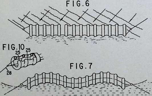
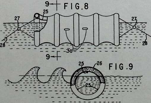
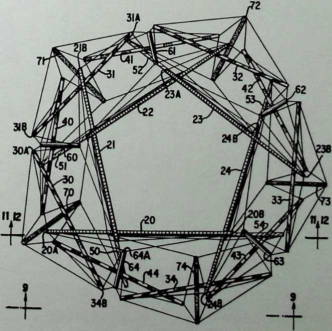
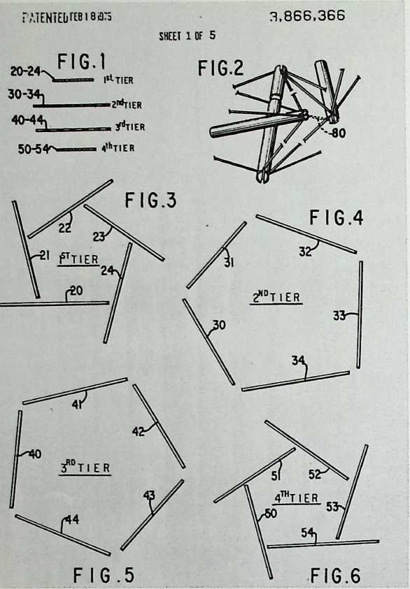
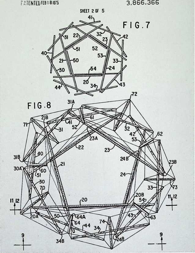
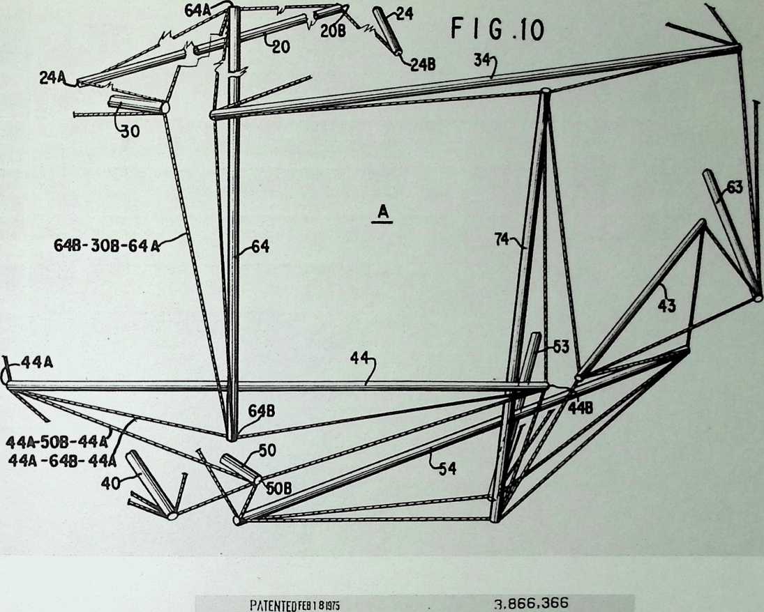
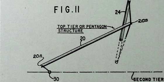
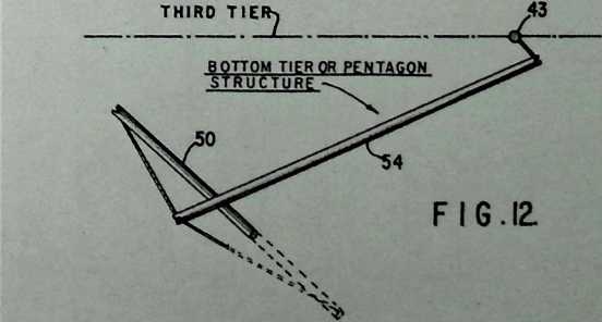
Nonsymmetrical Tensegrity Patent 2/18/75
Nonsymmetrical tensegrity dates from the early fifties, although Fuller did not patent this system until 1975. One notable example of its potential use is the portable theater he designed for St. Peter’s College, Oxford, in 1969.
United States Patent [19) Fuller
mi 3,866,366
[45] Feb. 18, 1975
[54] NON-SYMMETRICAL
TENSION-INTEGRITY STRUCTURES
[761 Inventor: Richard Buckminster Fuller, 200
Locust St… Philadelphia, Pa. 19106
(22) Filed: Aug. 7, 1973
(2I[ Appl. No.: 386302 (52[ U.S. Cl 52/81, 52/648
[51] Int. Cl E04b 1/32
(58) Field ot Search 52/81. 648
[56] References Cited
OTHER PUBLICATIONS
The Dymaxion World of Buckminster Fuller, Robert Marks. 1960, Reinhold Pub. Corp., pp. 160-161, FIG. klf.
Primary Examiner— Ernest R. Purser Assistant Examiner—Carl D. Friedman Attorney, Agent, or Firm—Smythe & Moore
(571 ABSTRACT
A building structure composed of column-like discontinuous compression members held by a plurality of tension elements, the column-like compression members being held in spaced relation by tension elements attached adjacent the ends of the column-like compression members. In the form shown, there are what can be termed two substructures, one at the top and one at the bottom, each substructure having pentagonal configurations of parallel lesser circles formed by column-like members and tension elements at its base, said pentagonal configurations being twisted relative to each other so as to provide rectangular openings therebetween. There are column-like compression members between the substructures held in spaced relation to each other and to the substructures by tension elements. The entire combination produces a generally spherical-like building structure.
7 Claims, 12 rawing Figures
Z.TENTEOFEB I8B5 3.866.366
SHEET 3 OF 5
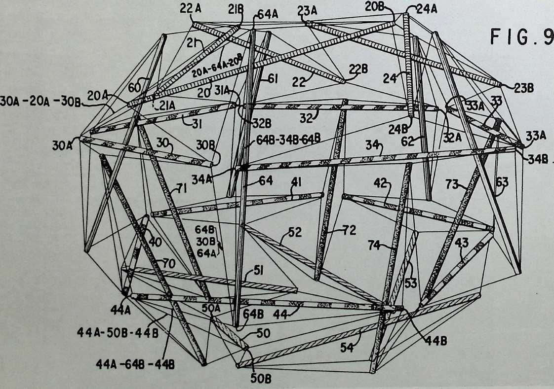
PATENTED FEB 181975 3.866,366
SHEET U OF 5
SHEET 5 OF 5
Allegra Dome
1975
This dome might have been intended as a greeting or might be an early stage of a project for Fuller’s daughter.
/0 ME&R/i
Zb/J'/ST l?7
SVA/JE
Ml
u /£/£€?? A
I
’ 7 7
![]()
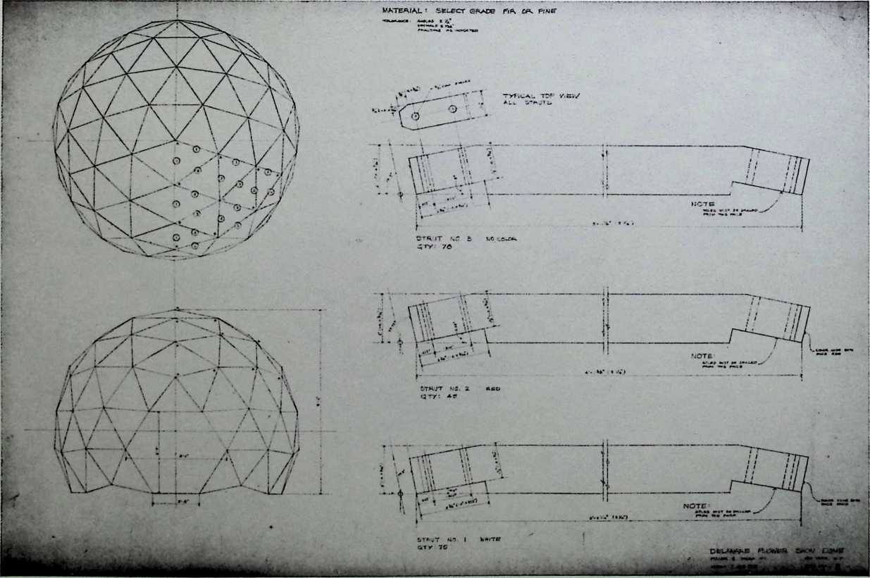
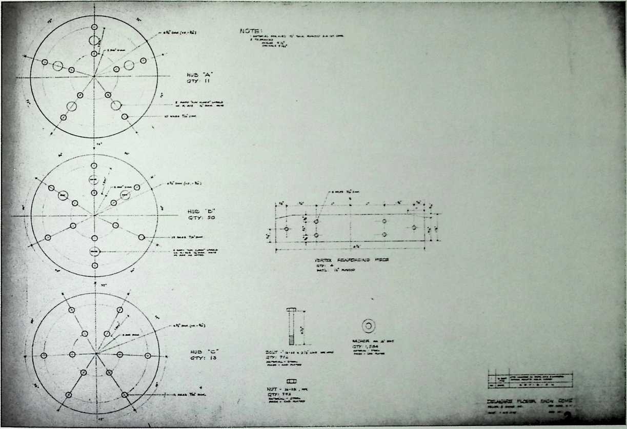
Delaware Flower
Show Dome
Fuller & Sadao, 1975
This white enameled dome was constructed of pine struts with plywood hubs for the Delaware Flower Show of 1976. Perhaps intended to promote the idea of the geodesic greenhouse, this relatively small structure (nineteen feet wide and fifteen feet high) was not glazed nor was a solid hexagonal door planned for its entrance. Particularly noteworthy is the fact that the frequency of this dome results in an irregular base.
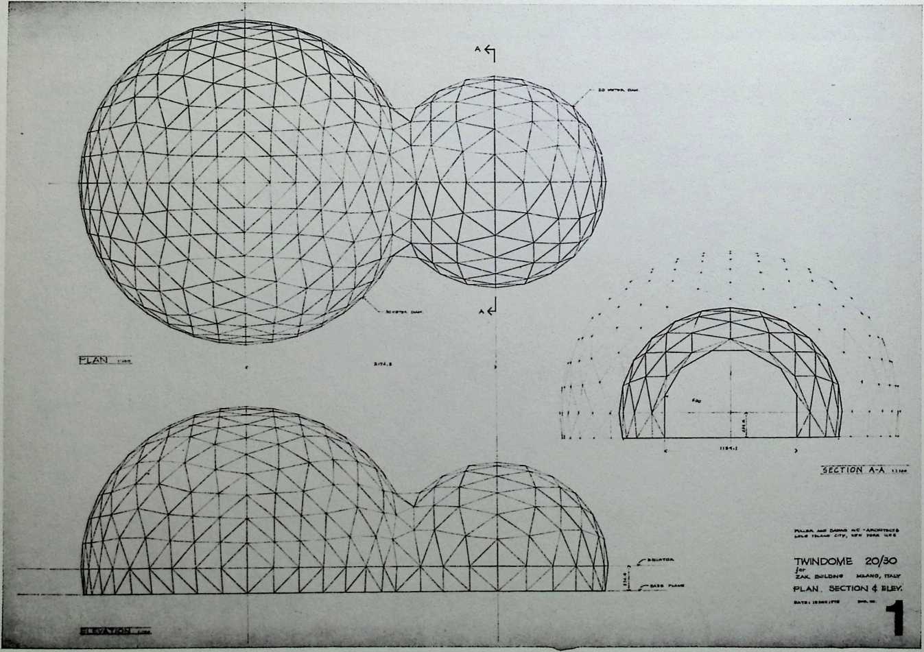
Twindome 20/30
Fuller & Sadao, 1975
The twindome expanded the planning possibilities of the geodesic volume.
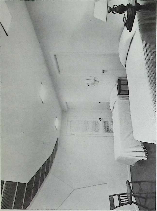
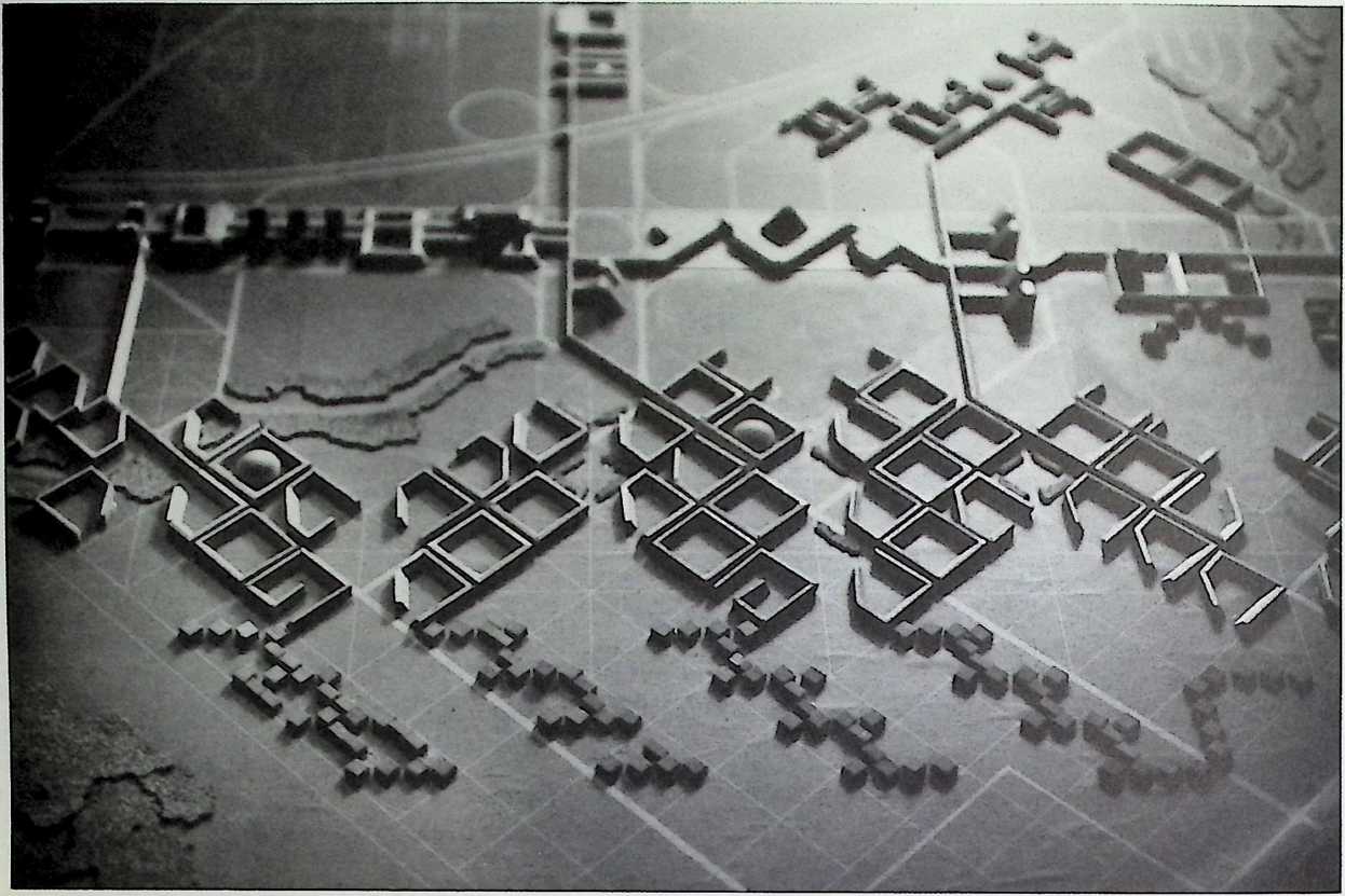
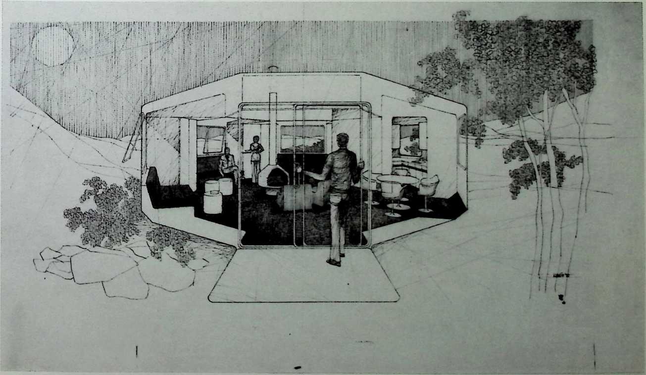
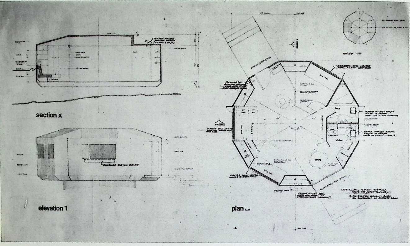
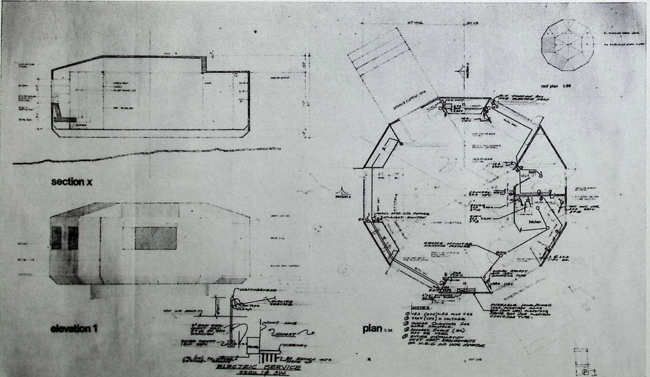
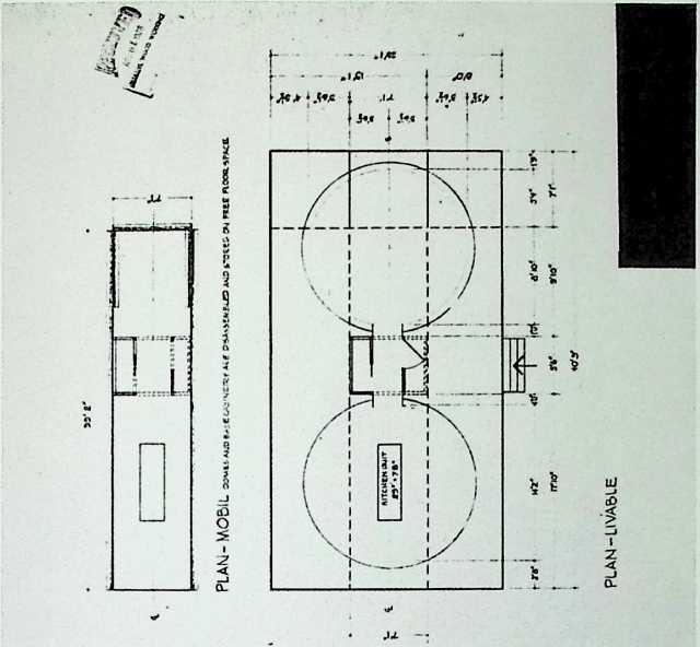
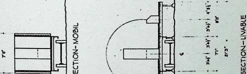
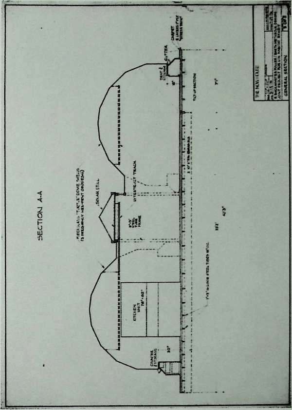
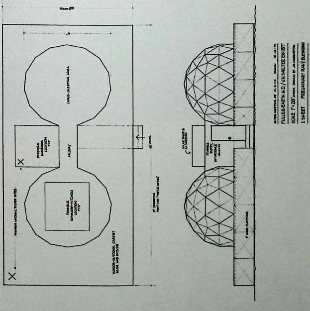
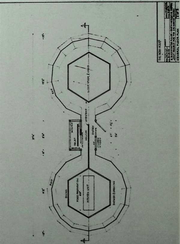
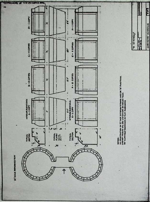
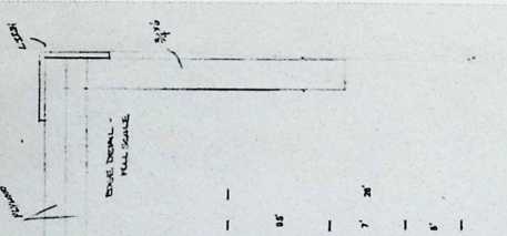
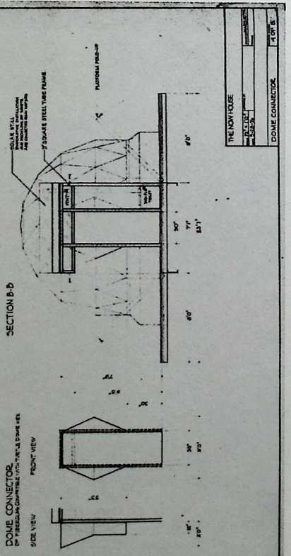
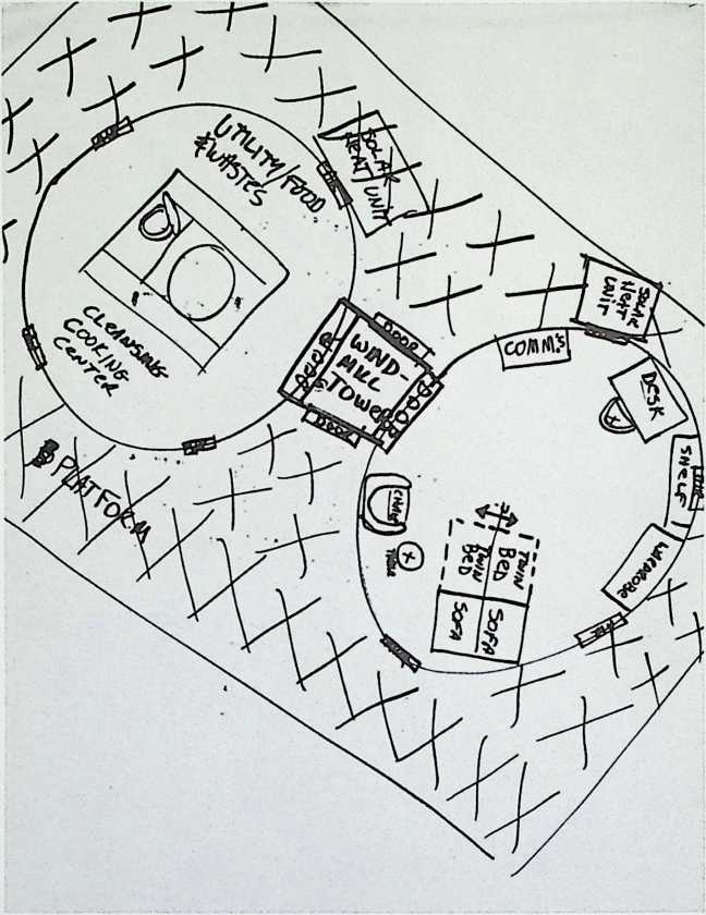
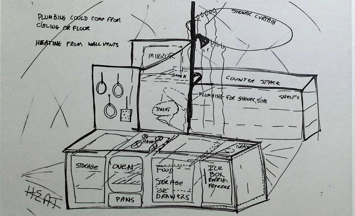
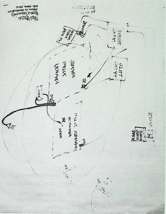
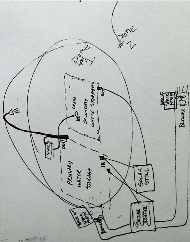
The Now House
1975-1976
The Now House broadened the horizons of geodesic structures in being a minimal dwelling of two domical rooms connected by a rectangular vestibule. It was designed by Fuller for the United Nations Habitat Exhibition in 1976.
![]()
![]()

Ft MW 70 fa. cPtnvc.rro/O
TutrF»y 6fa4tn, to* —
Wer» uotrthG
Ca&*To
![]()
![]()
F orty-four-Foot-Diameter
Duplex Dome
Fuller & Sadao, 1976
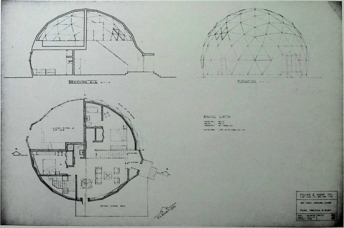
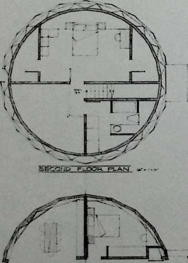
The novelty of this design relies on the combination of the duplex type (a phenomenon that developed as a result of the housing shortage after World War I) and the geodesic dome. The two entrances are set on a diagonal line off axis with respect to the floor plans. Each of the two housing units has two bedrooms, two bathrooms, a dramatic, two-story living room, and a shared sun deck (optional).
Thirty-four-F oot-Diameter
Single-Family Dome
Fuller & Sadao, 1976
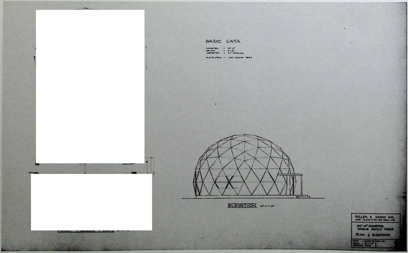
With its one large bathroom and a large master bedroom, this two-story geodesic dome provides an interesting alternative to the typical row house. A corridor runs through the center of the dome to the front and rear entrances. The corridor upstairs that connects the master bath and bedroom is cantilevered dramatically above the two-story living room. Fuller explored the possibilities of geodesic fenestration, with the large hexagonal window of the living room, and the modified ribbon window of the kitchen.
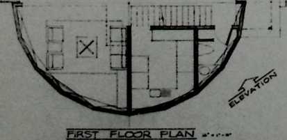
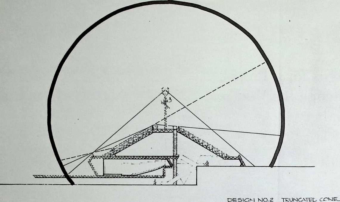
Designs for a Proposed Geoscope for Montreal, Canada
The geoscope, if executed, would be a planetarium with a lecture hall and a capacity for 2,500 spectators.
1976
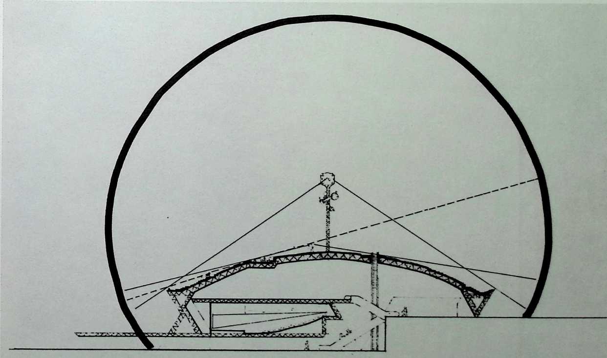
isr-.CTiObj iz i&- •. f-o-
T K.CTO5E.L GEOKCPE MB MONTEEAL CA.NAUA, ■cwa-a’ tsie; «=»y r… fxoruxtO'-v A u bmowm fog*. v?. eocKAAikxrniw. fugles?.
7(tr CfJ 2.0-
CAPAT.ITY CF MAIN S+AOE. ’ 100
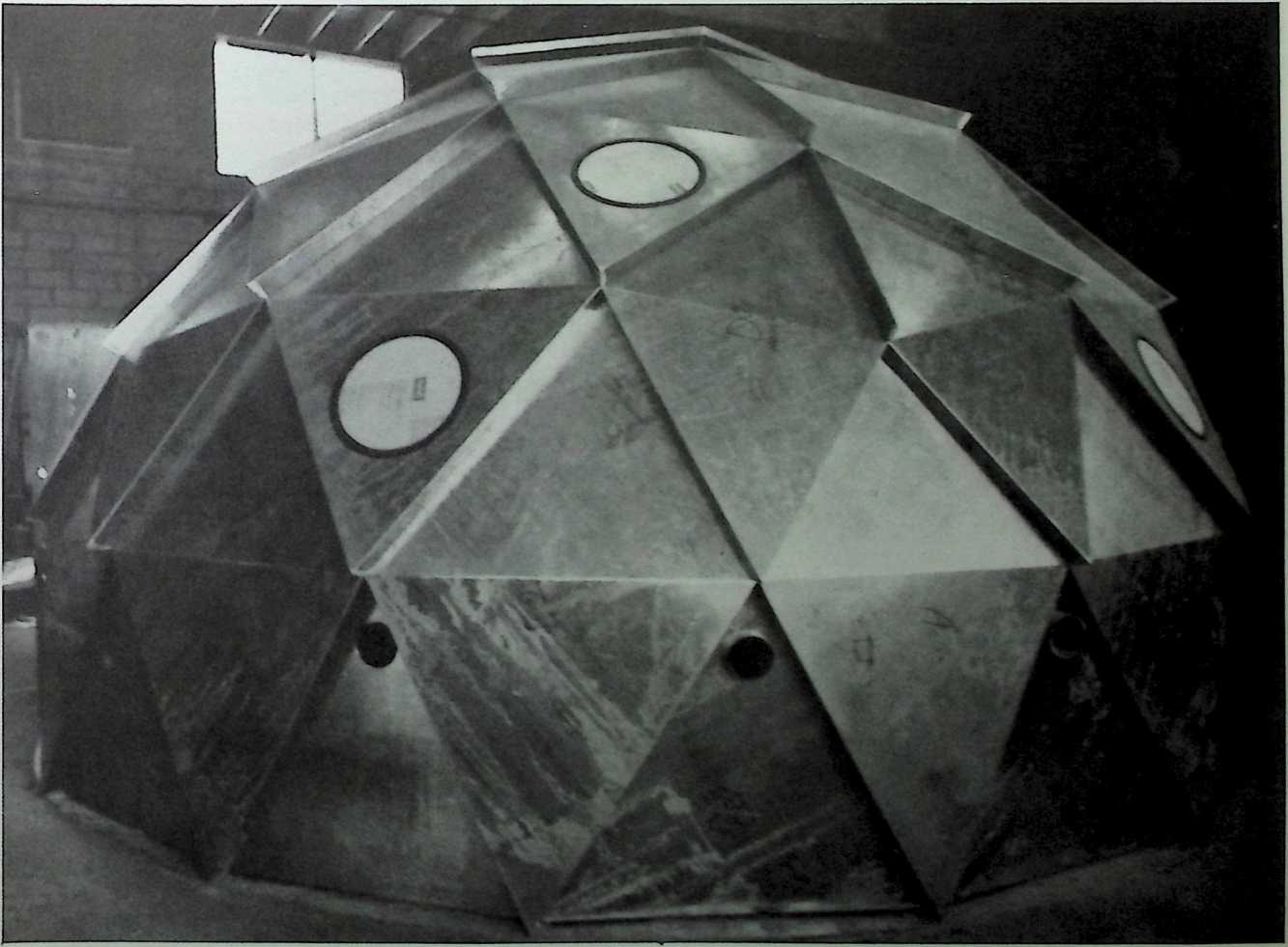
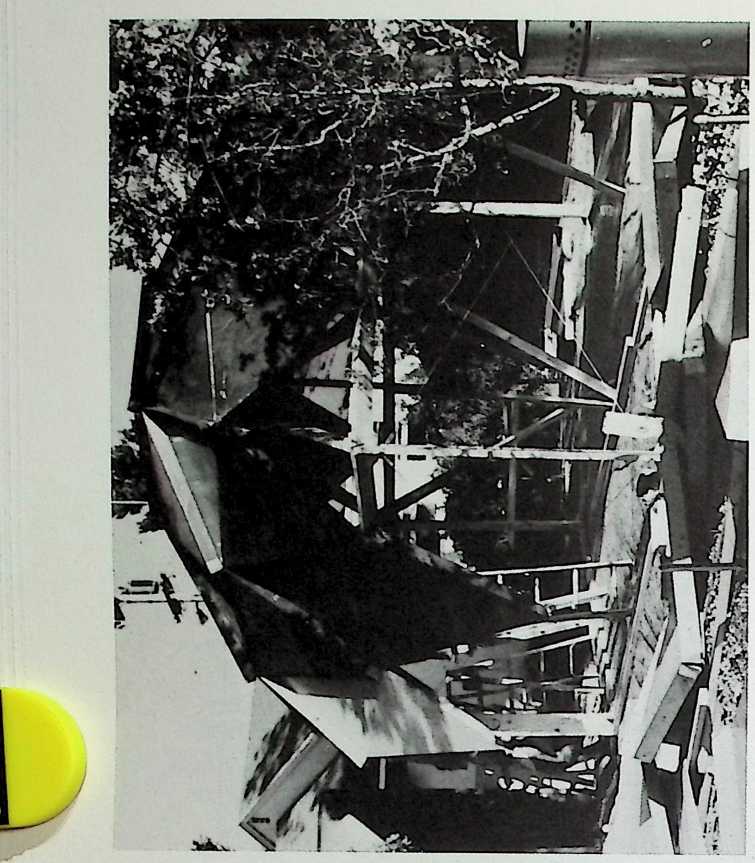
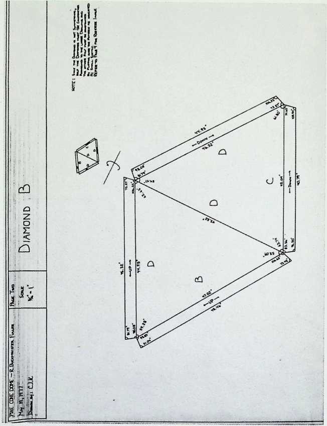
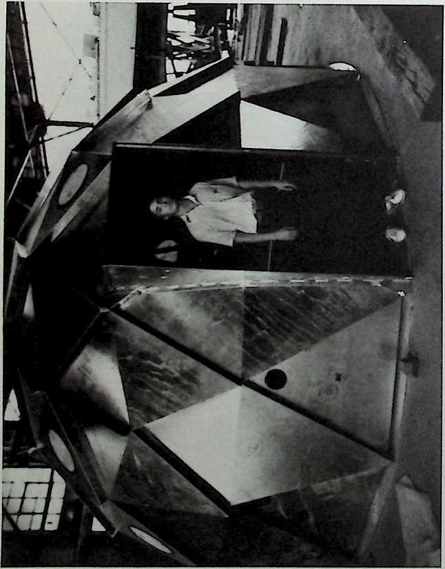
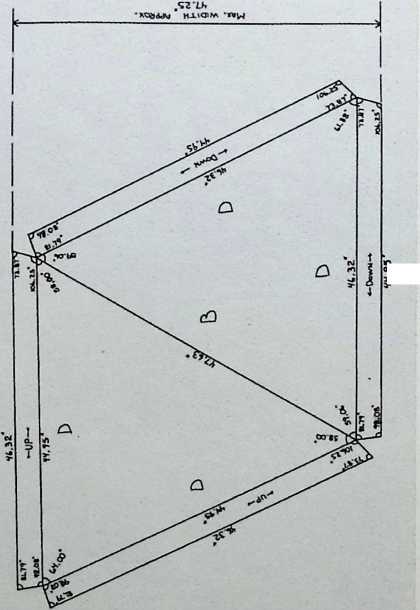
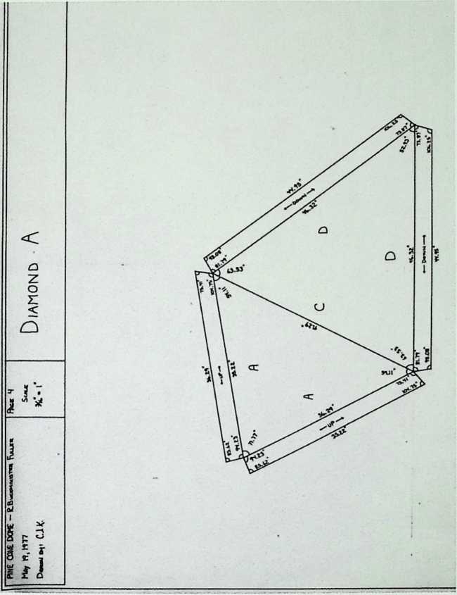
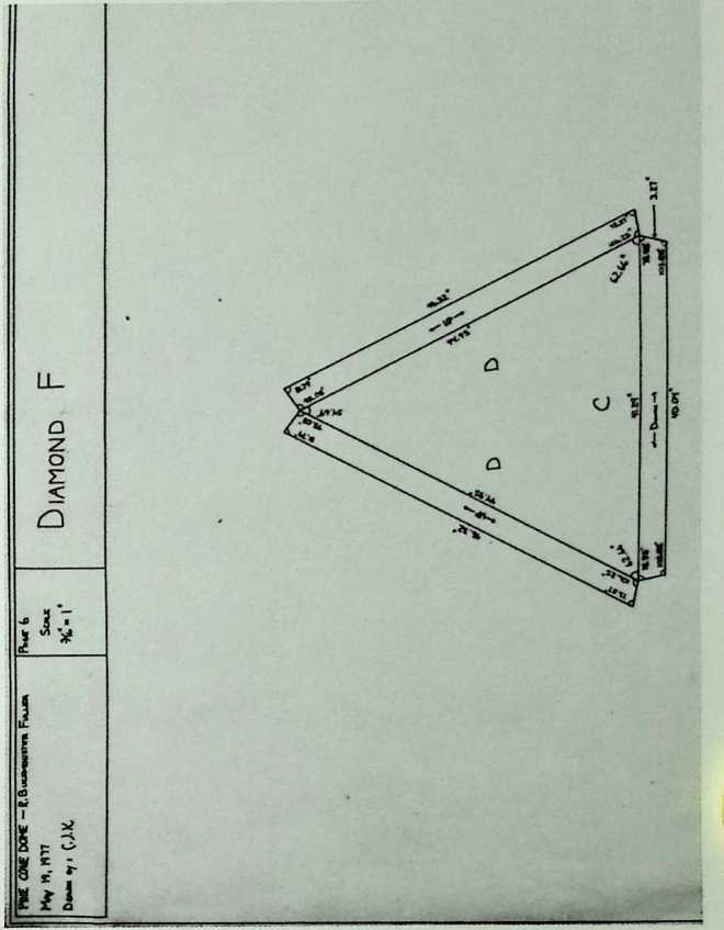
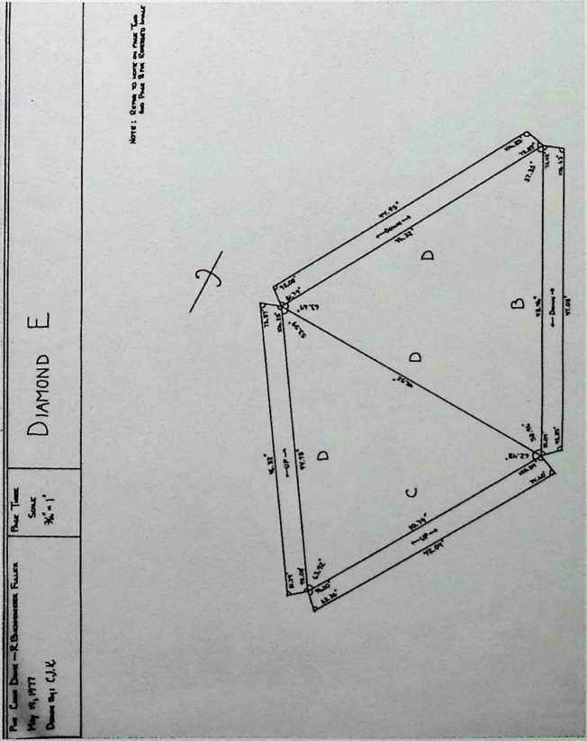
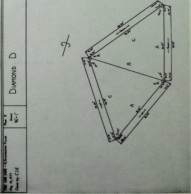
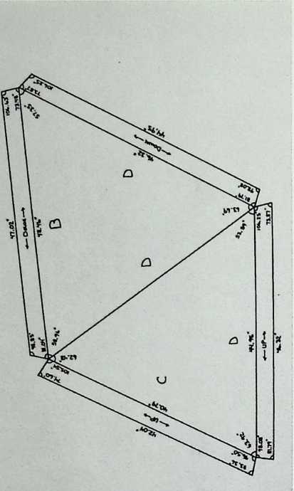
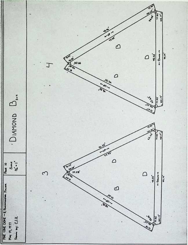
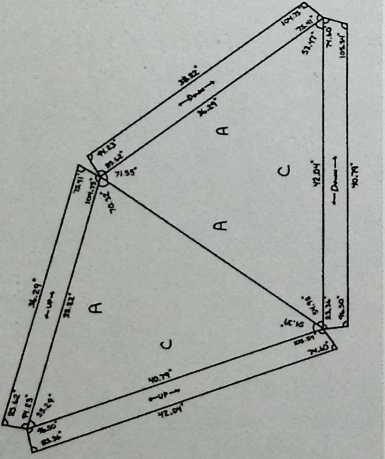
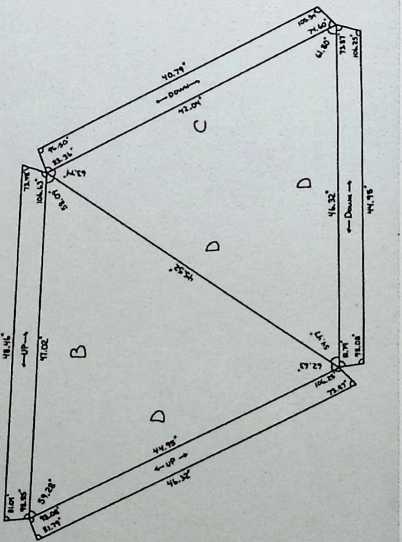
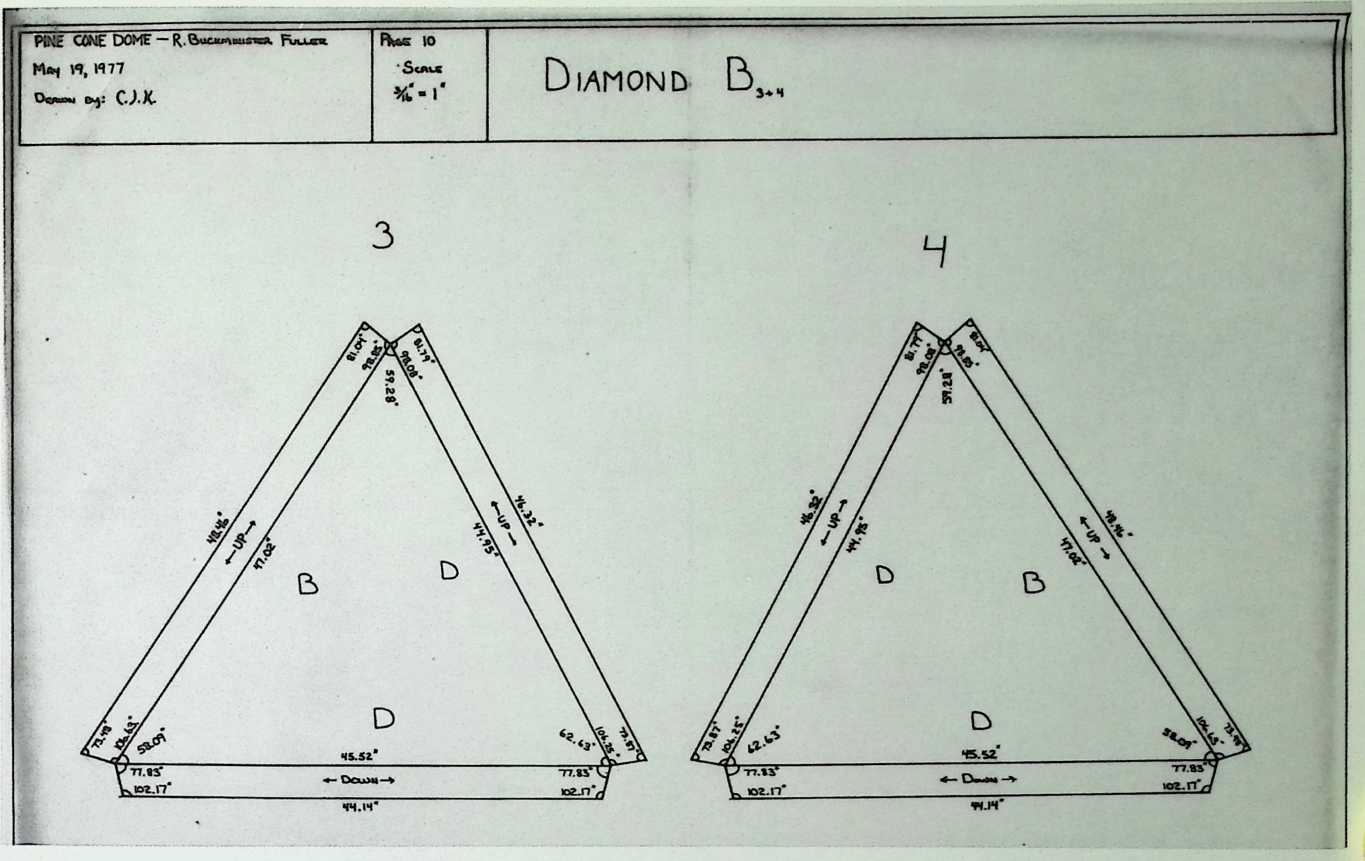
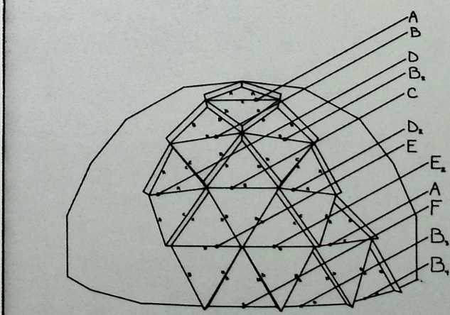
Pine Cone Dome 1977
This dome is essentially a revision of the laminar dome patent of 1965.
W.95
![]()
![]()
![]()
I
1 I 1!
I
~ J 7
![]()
![]()
![]()
HNE CONE DOME — R. BucKMwsrea Fu-m
M*, H, I’m
CJ-K-
![]()
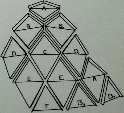
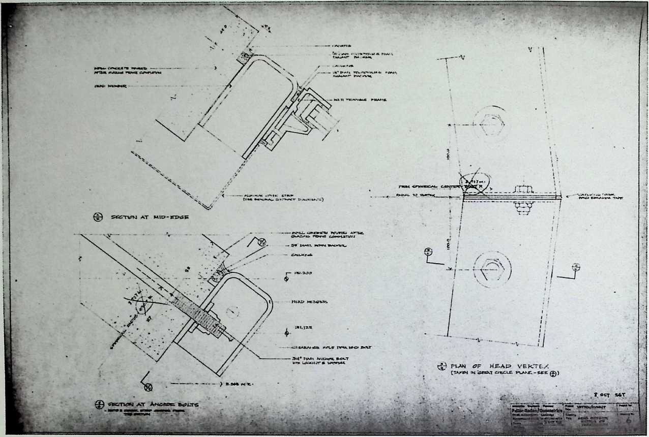
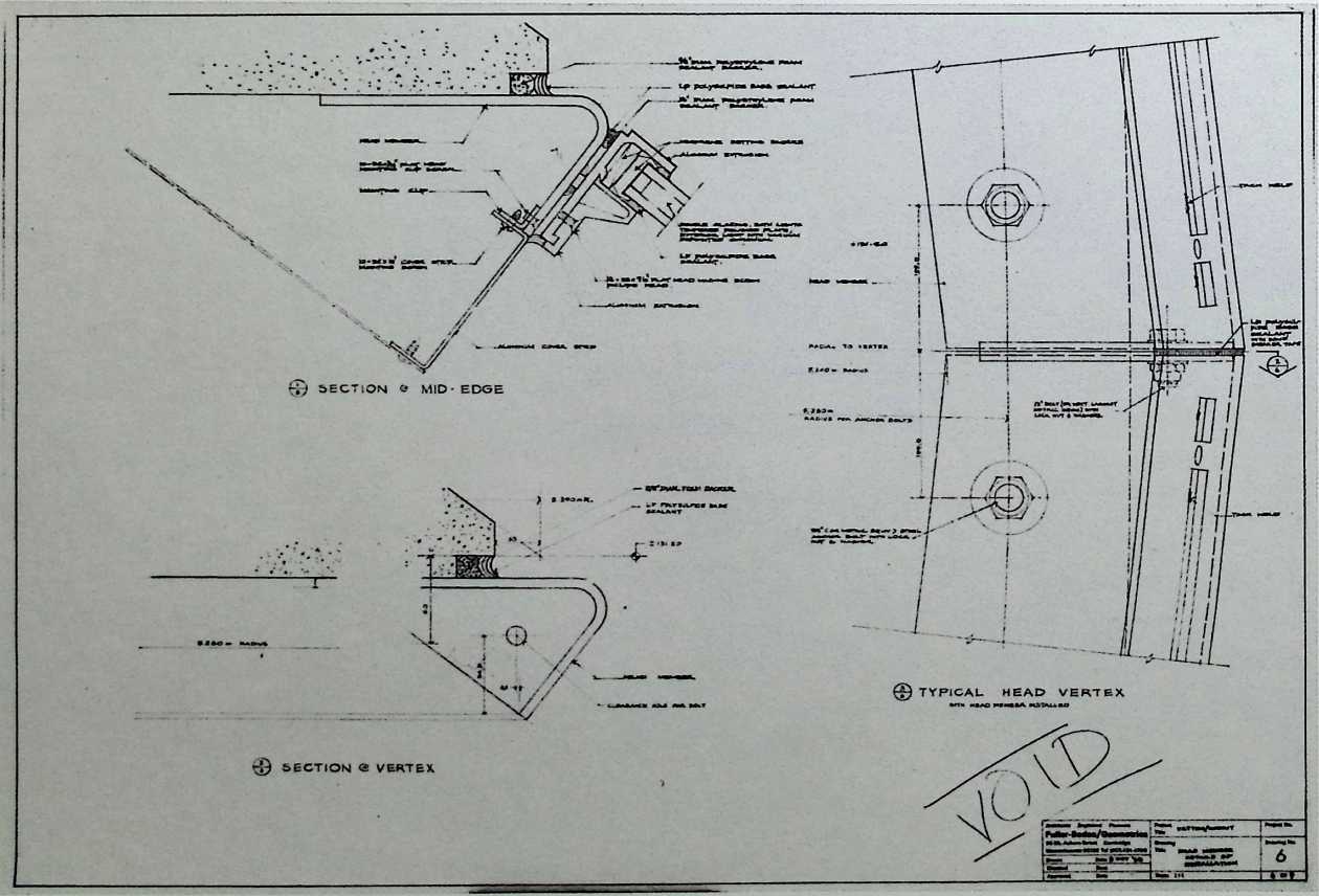
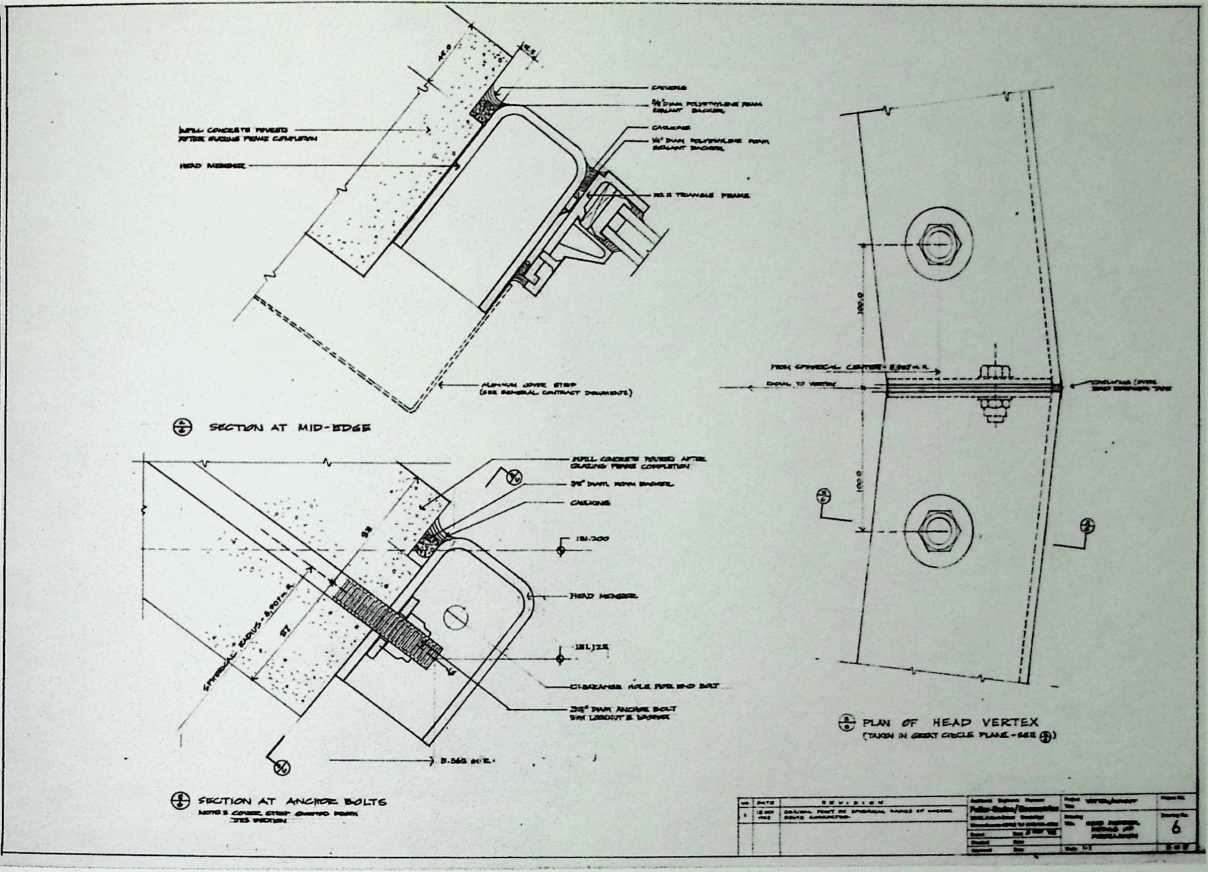
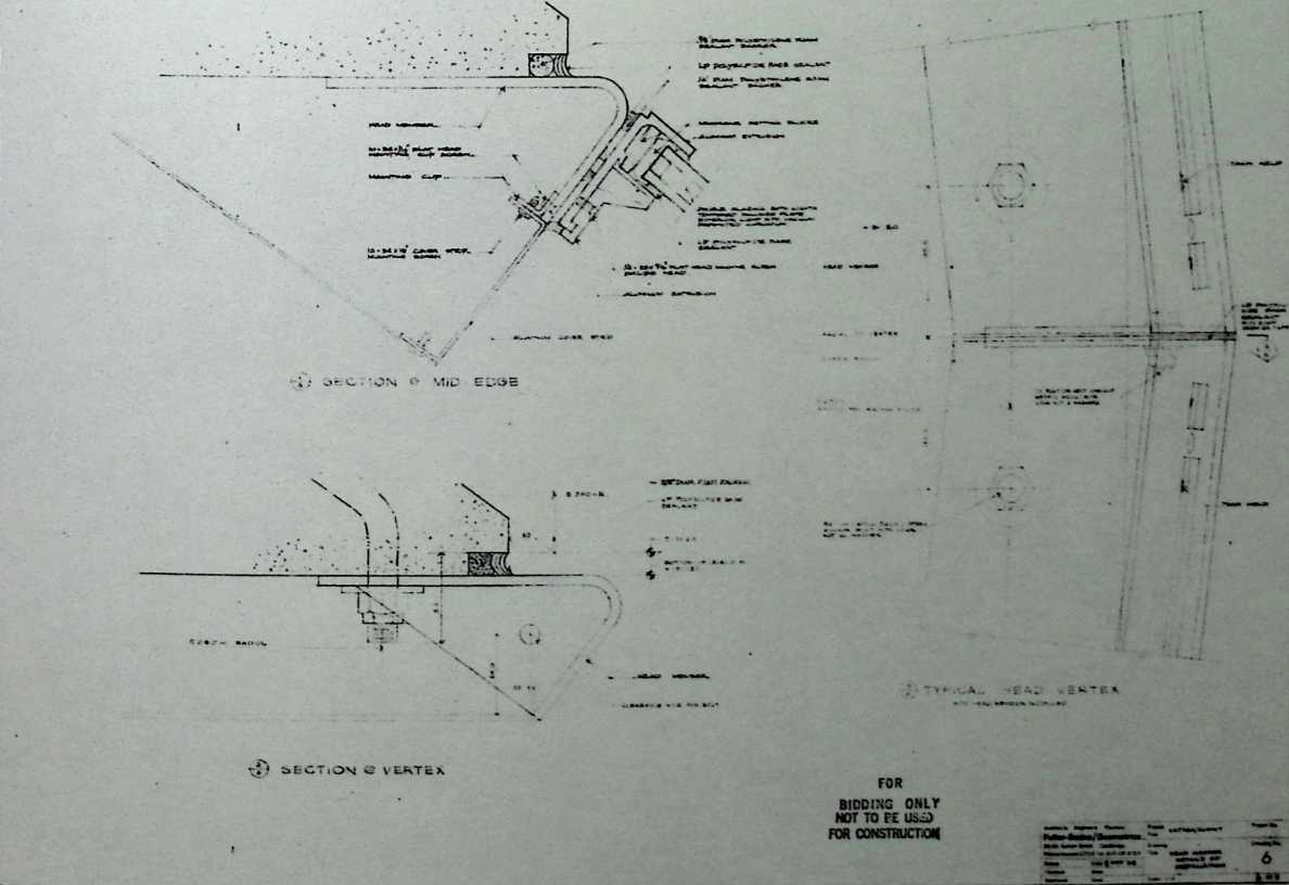
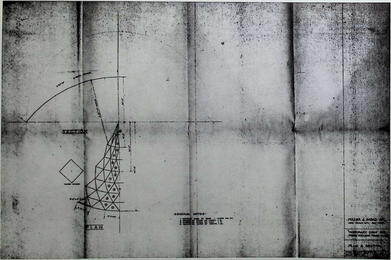
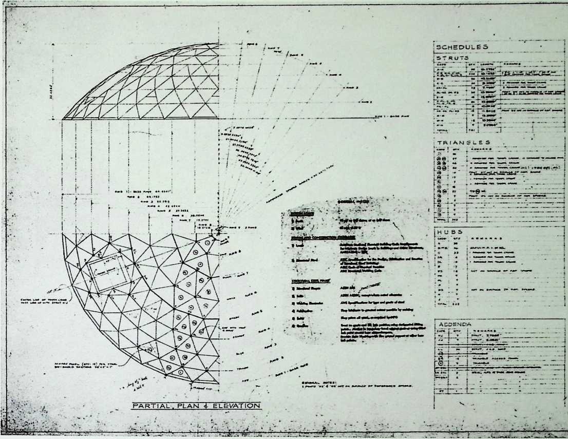
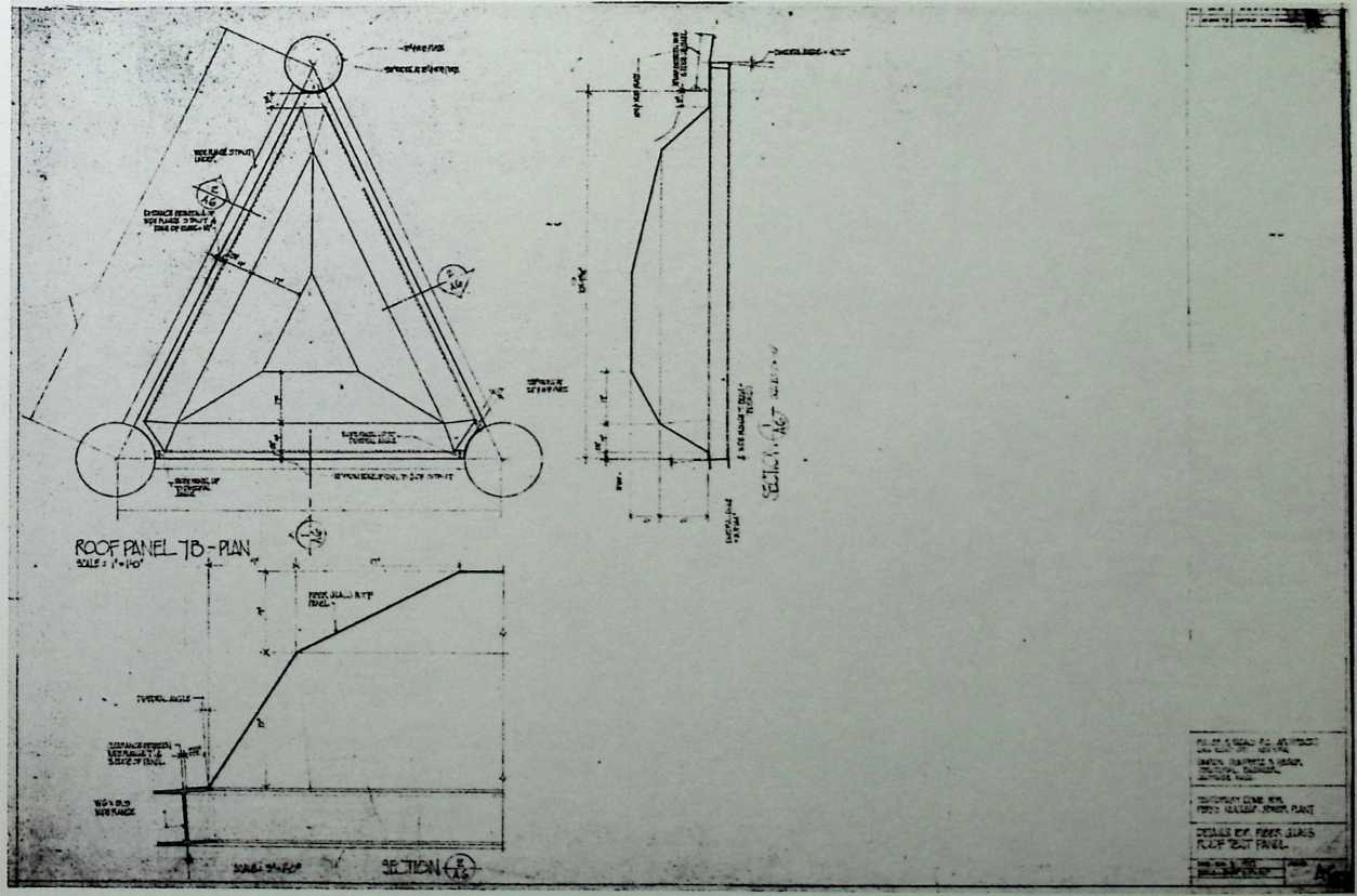
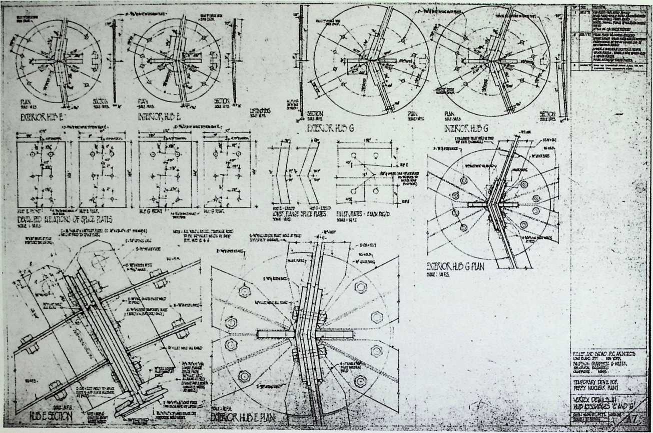
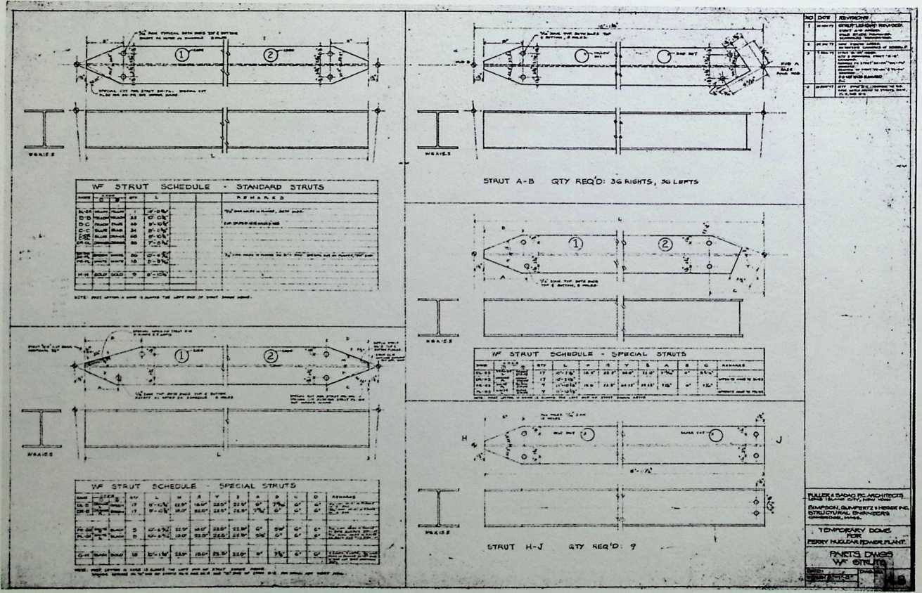
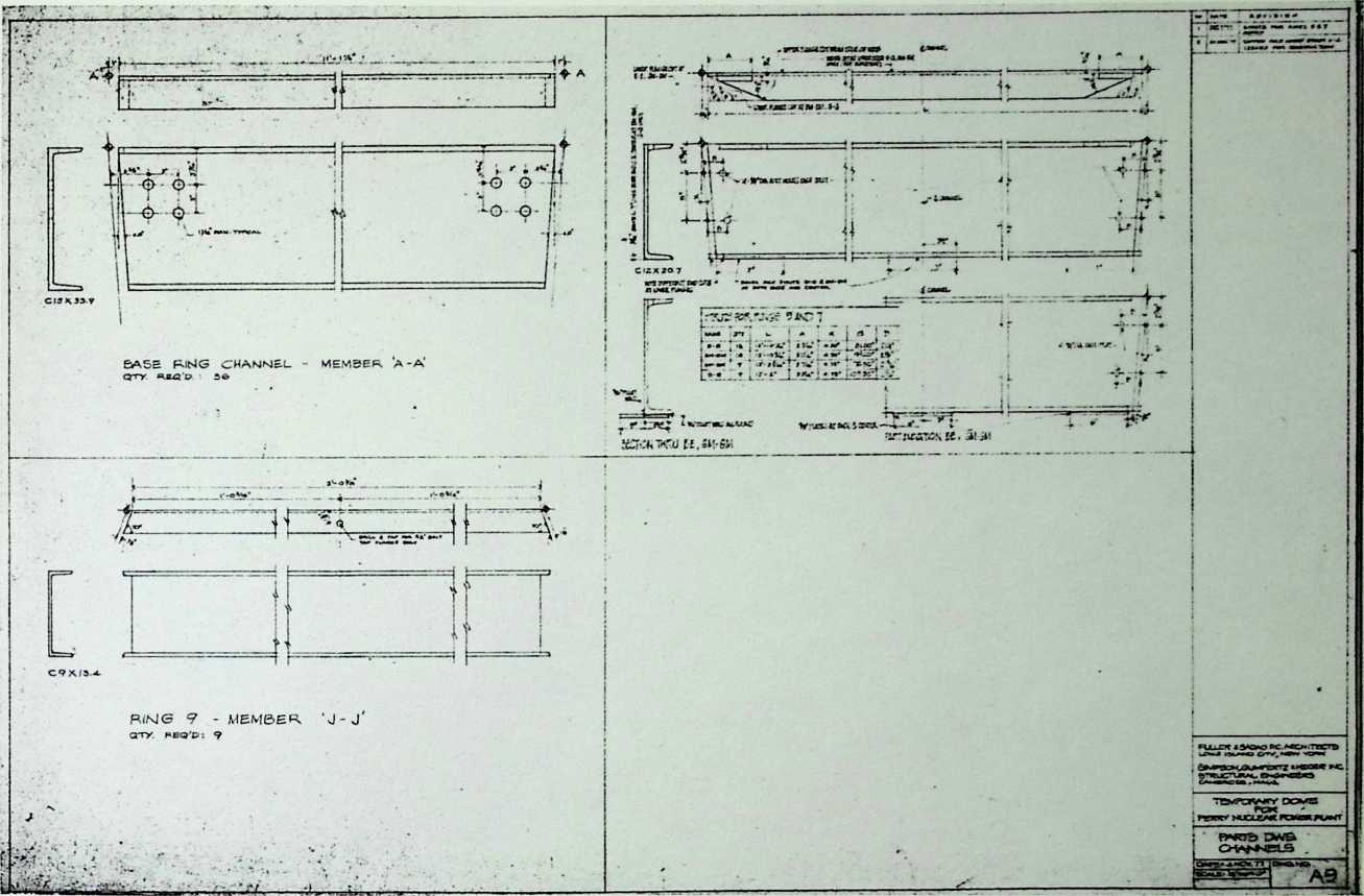
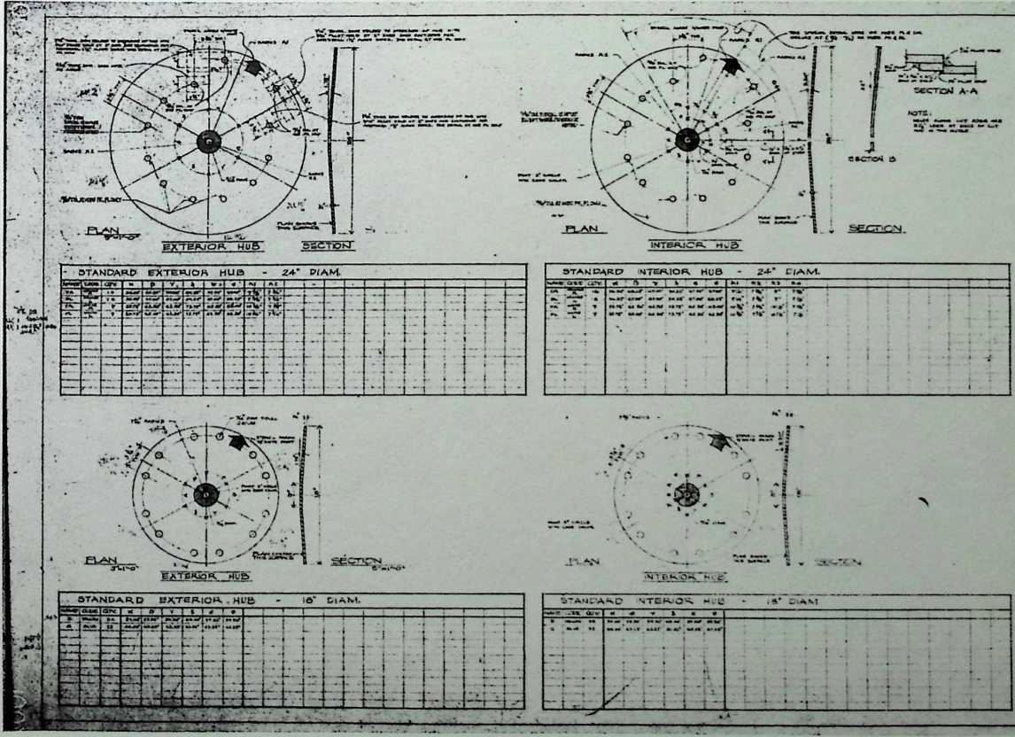
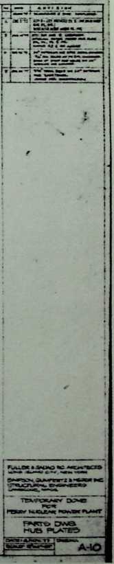
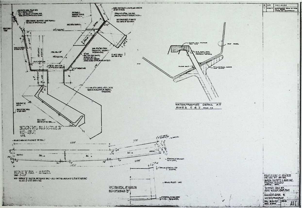
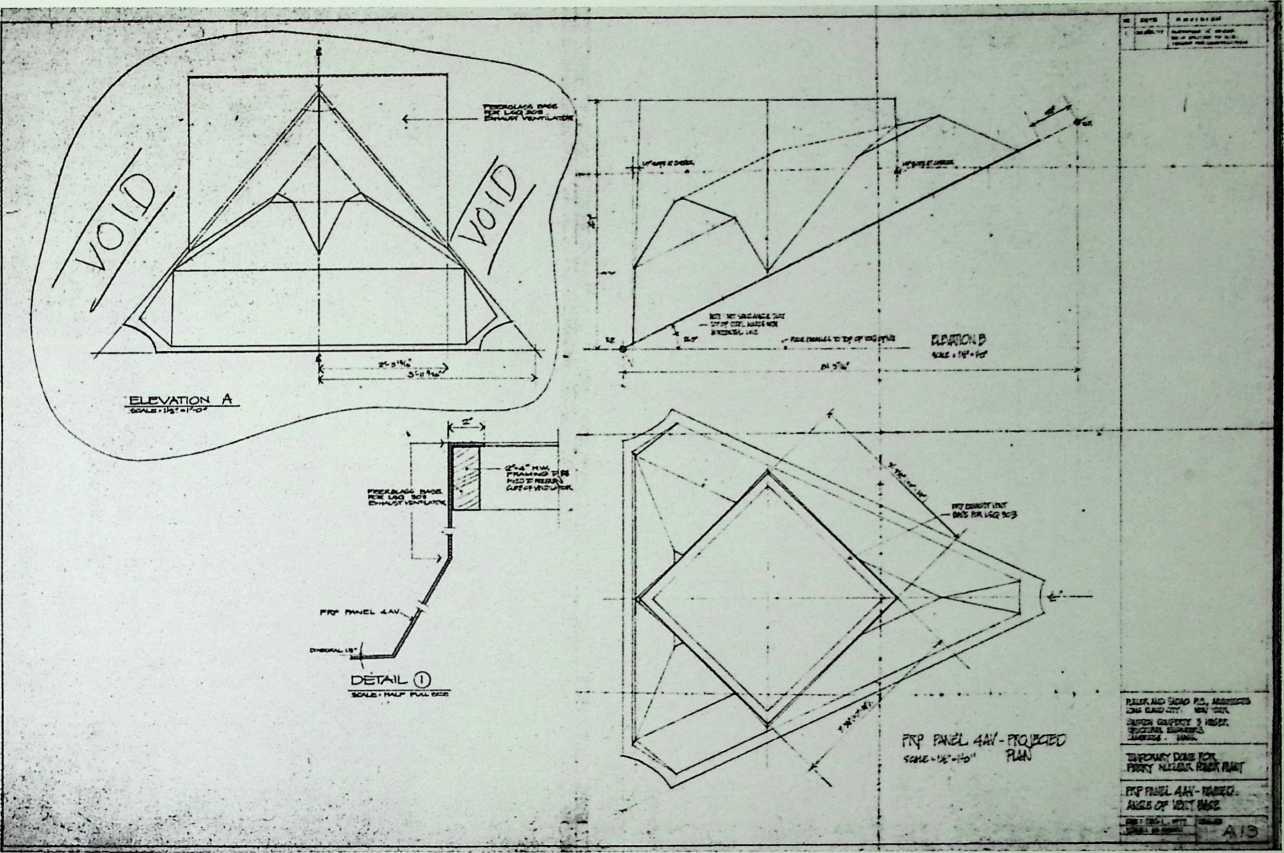
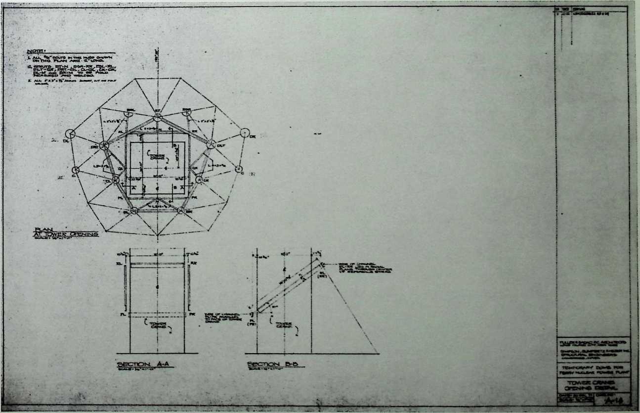
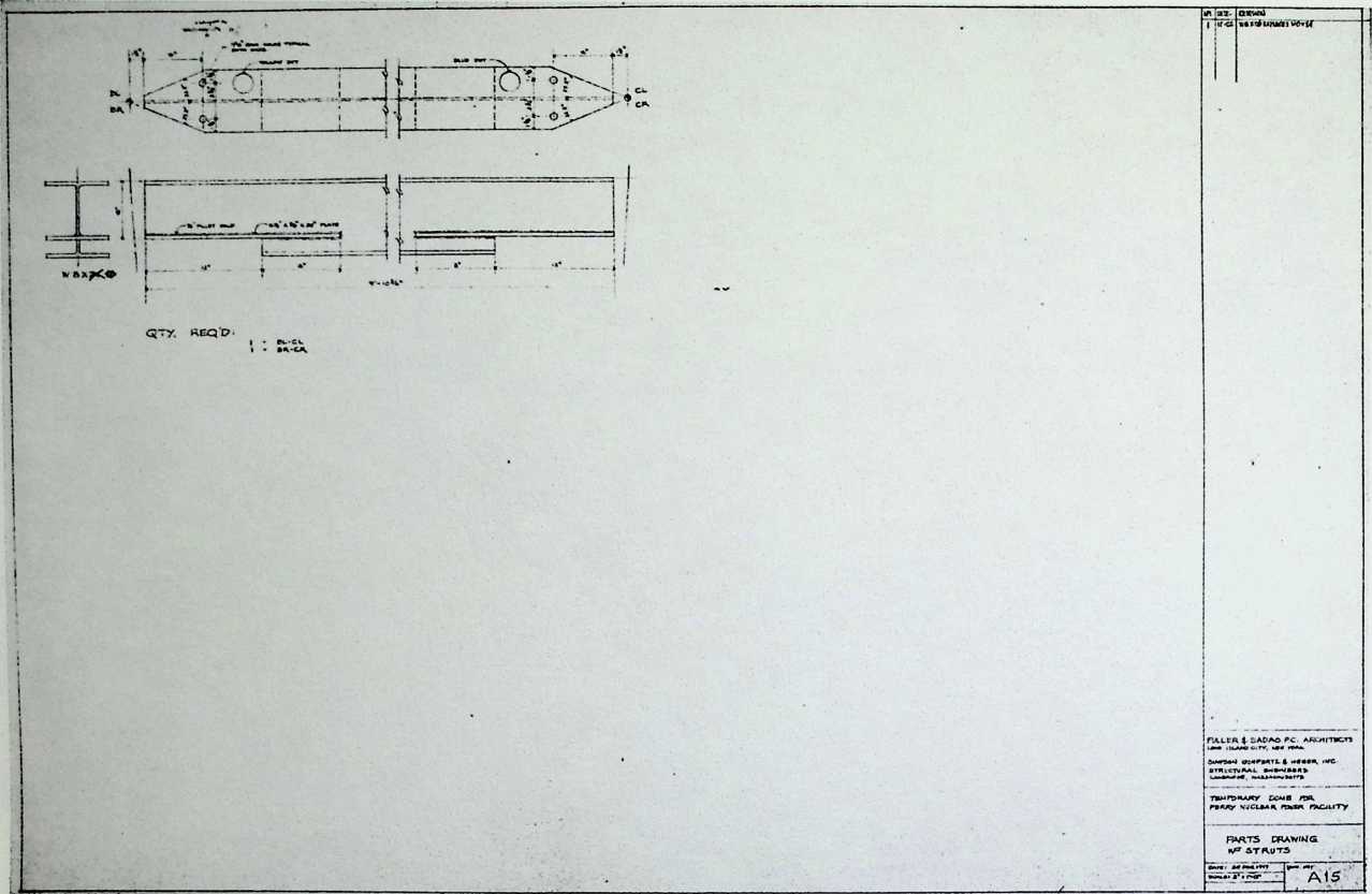
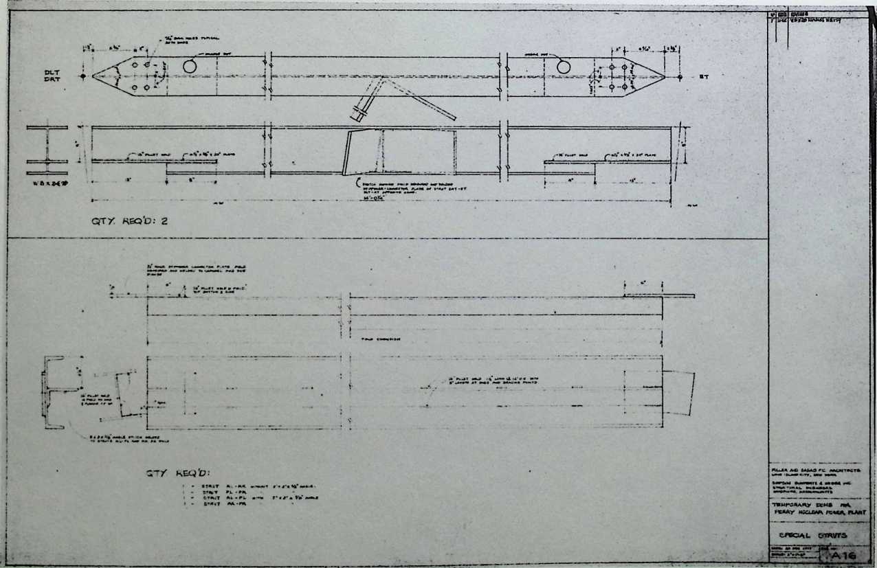
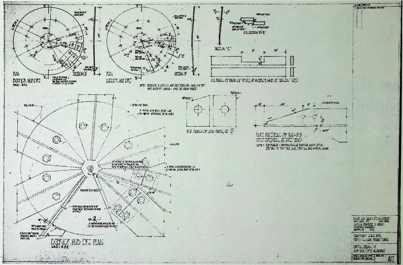
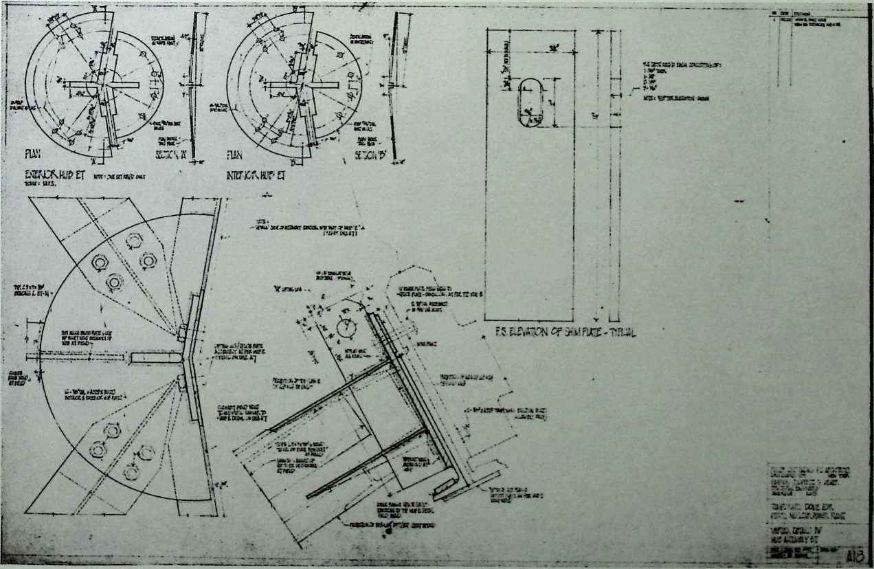
Temporary Dome for the Perry Nuclear Power Plant, Perry, Ohio 1977
During the construction of the reinforced concrete dome of the nuclear powei' plant in Perry, Ohio, the interior was protected by a geodesic dome of Fuller’s design.
I
F
I
I
HIW wvkwiMG HUB M
![]()
L
THE GEODESIC REVOLUTION, PART 2 335
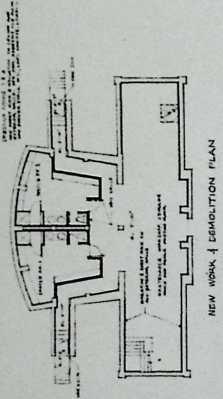
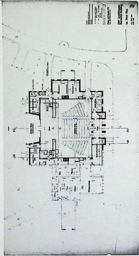
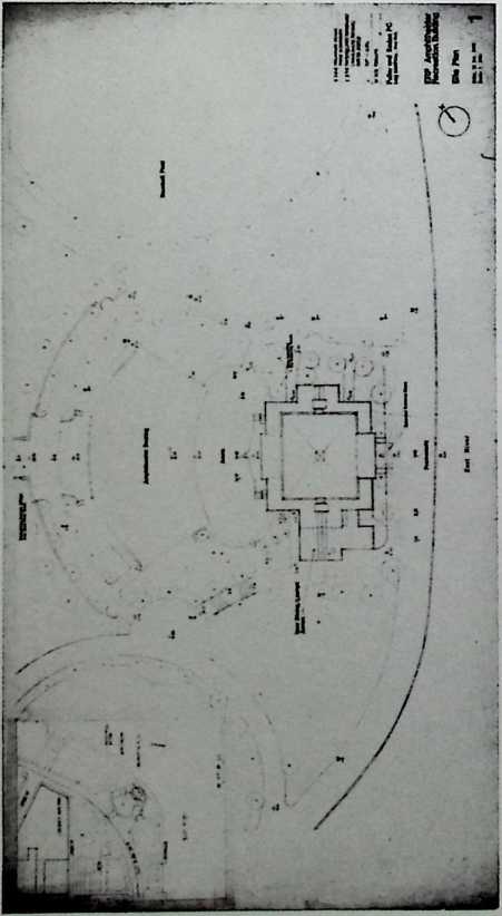
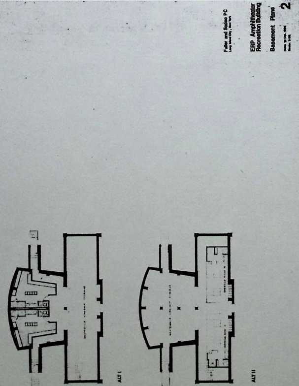
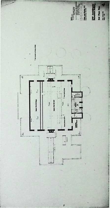
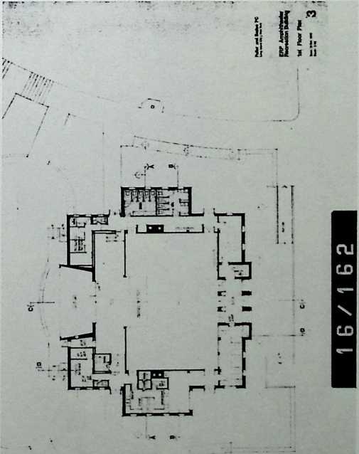
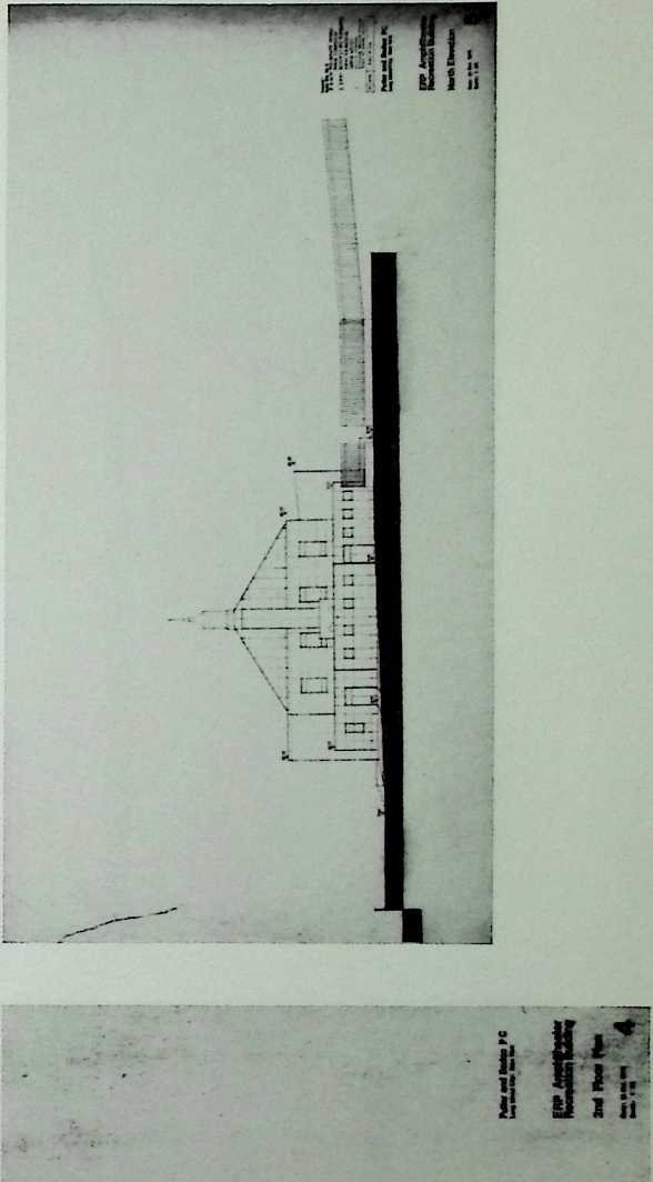
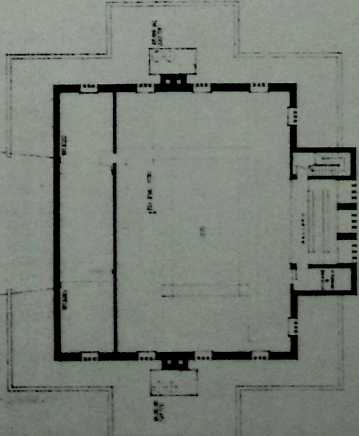
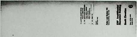
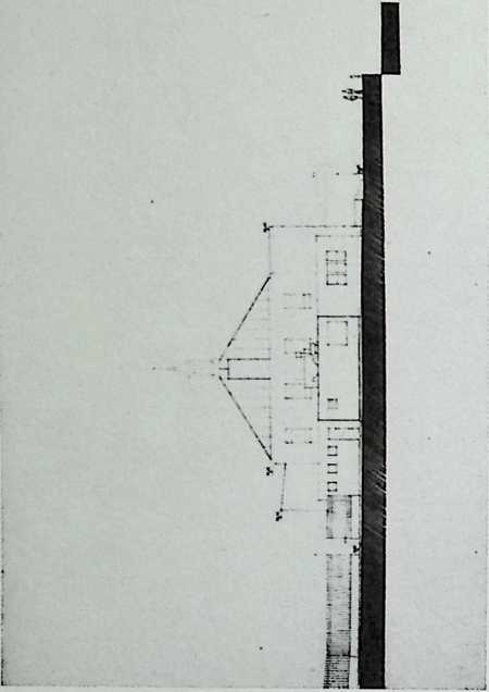
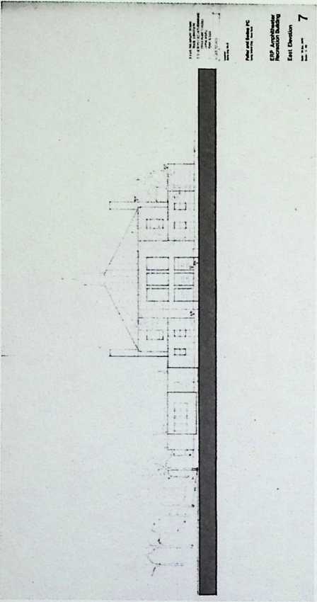
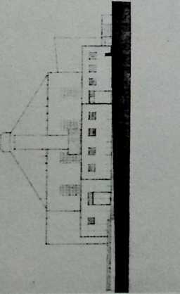
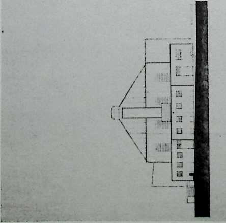
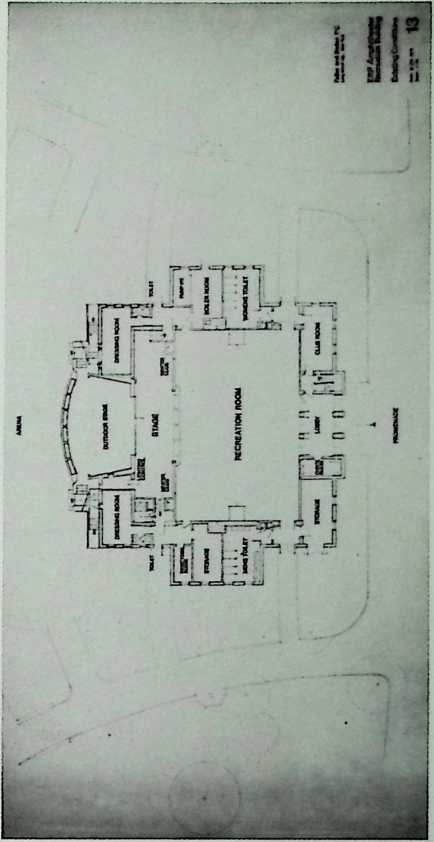
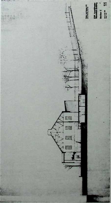
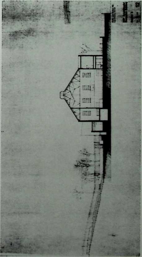
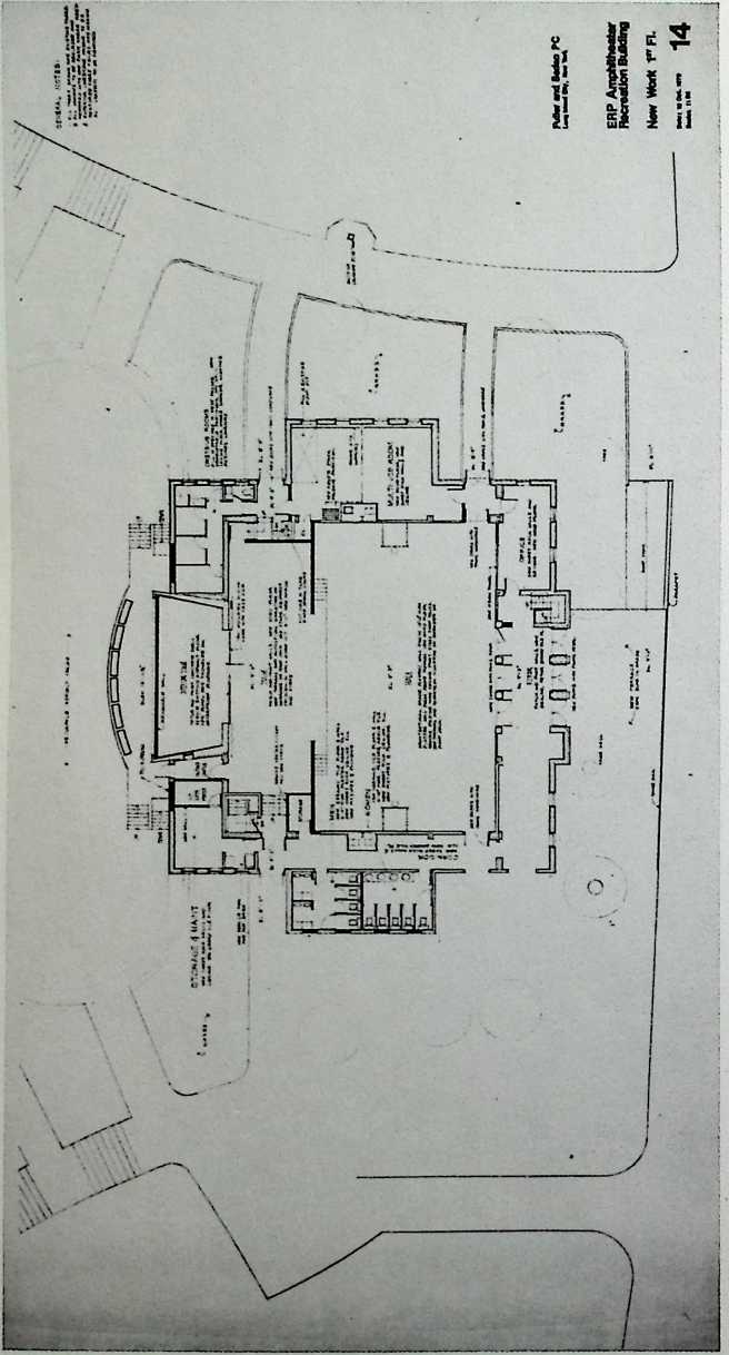
East River Park
Amphitheater,
New York City
Fuller & Sadao, 1977-1979
This is Fuller & Sadao’s solution to the renovationremodeling of an obsolete structure on the Manhattan side of the East River. Community groups and the theater’s future managers had considerable impact on the design adopted eventually.

THE GEODESIC REVOLUTION. P/\RT 2 343
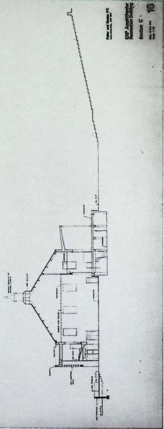
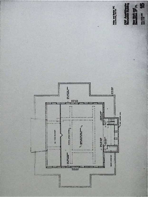
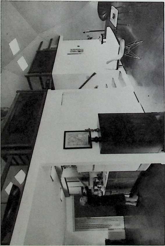
Space Theater for Dance and Noguchi Sets Designed by Isamu Noguchi 1978
This would have been an elegant, circular, two-story theater with a masonry base and a geodesic roof. The tiers of seats are reached by way of a bifurcating staircase, and their diagonal arrangement is reflected by the lines where the masonry of the walls meets the glazing of the dome. The performers enter from a trap-door elevator located at center stage.
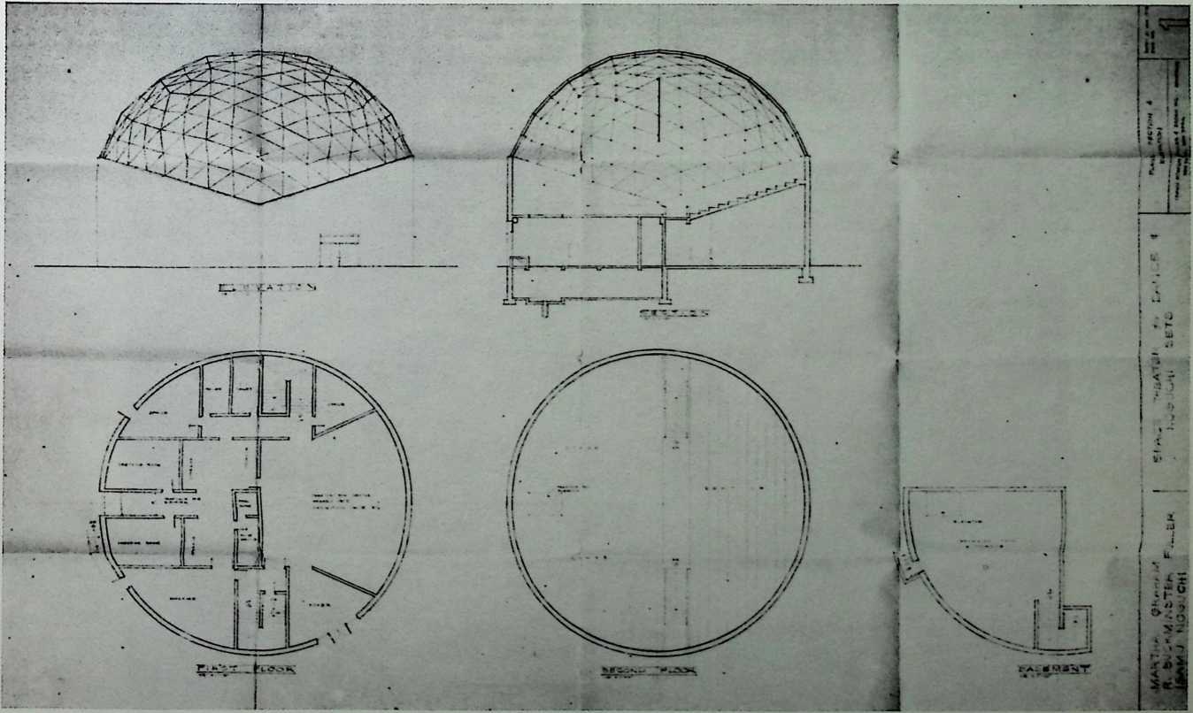
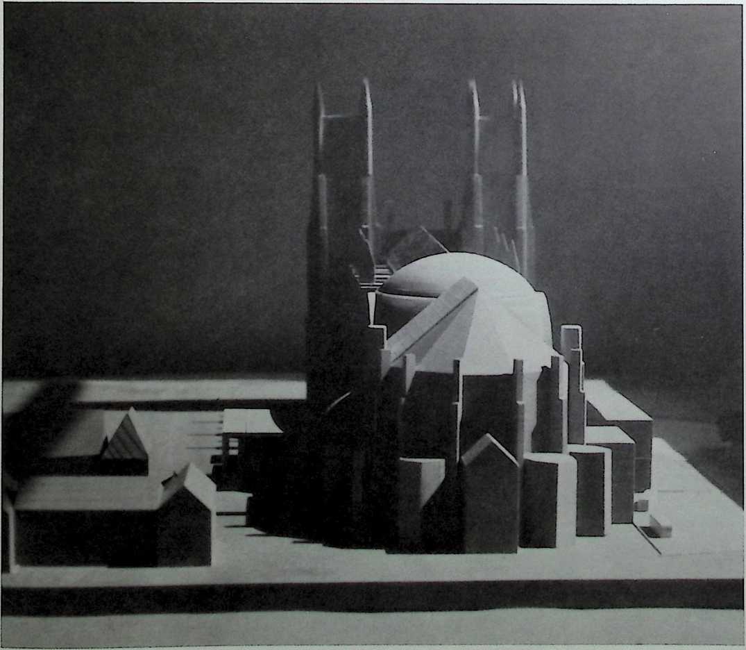
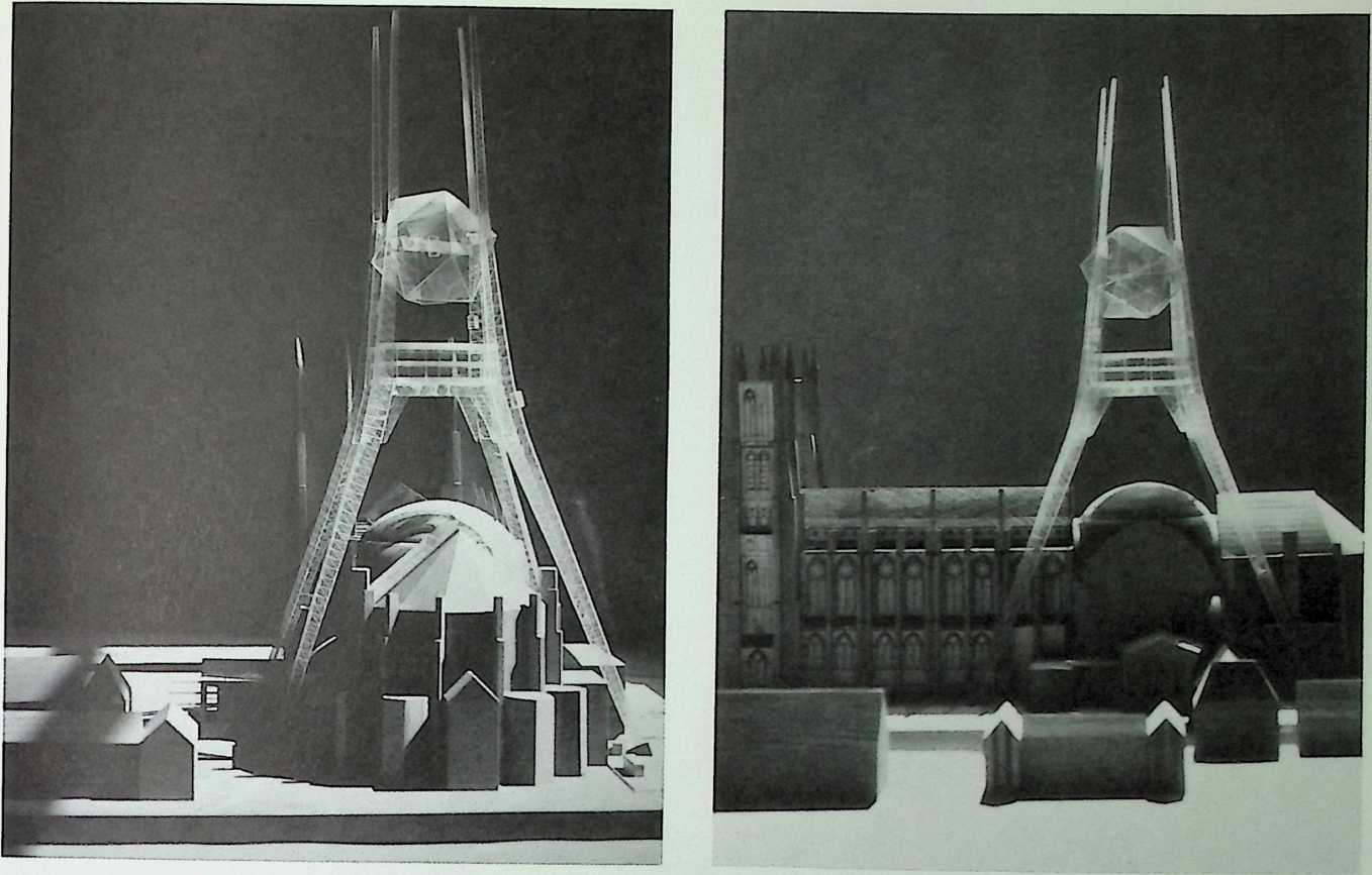
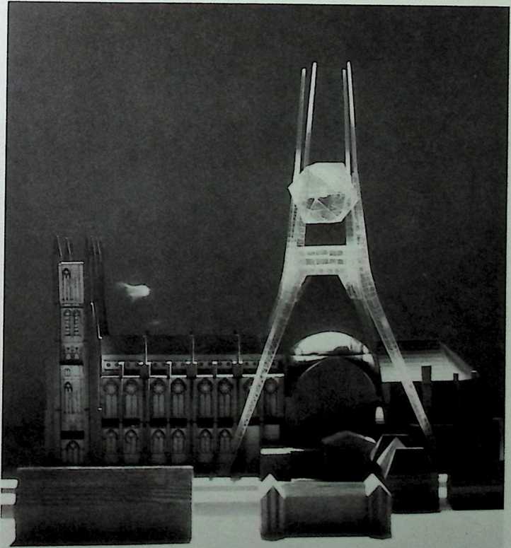
Icosahedron Tower for the Crossing of the Cathedral Church of St. John the Divine (Unexecuted), New York City Fuller & Sadao, 1978
This icosahedron truss tower designed by Fuller & Sadao for the crossing of the Cathedral Church of St. John the Divine might seem to upstage the massive neo-Gothic structure as designed by Ralph Adams Cram. Fuller’s revision of the design for the crossing would have incorporated four tall tetrahedron trusses in hyperbolic curves, forming a high-tech tower harmonious with existing stone finials. These supports were to be united by a large, open icosahedron and by an observation platform. The church trustees apparently decided to adhere to the master plan of 1911; and thus the piquant combination of Fuller’s futuristic structural style and its medieval antecedent remains unrealized.
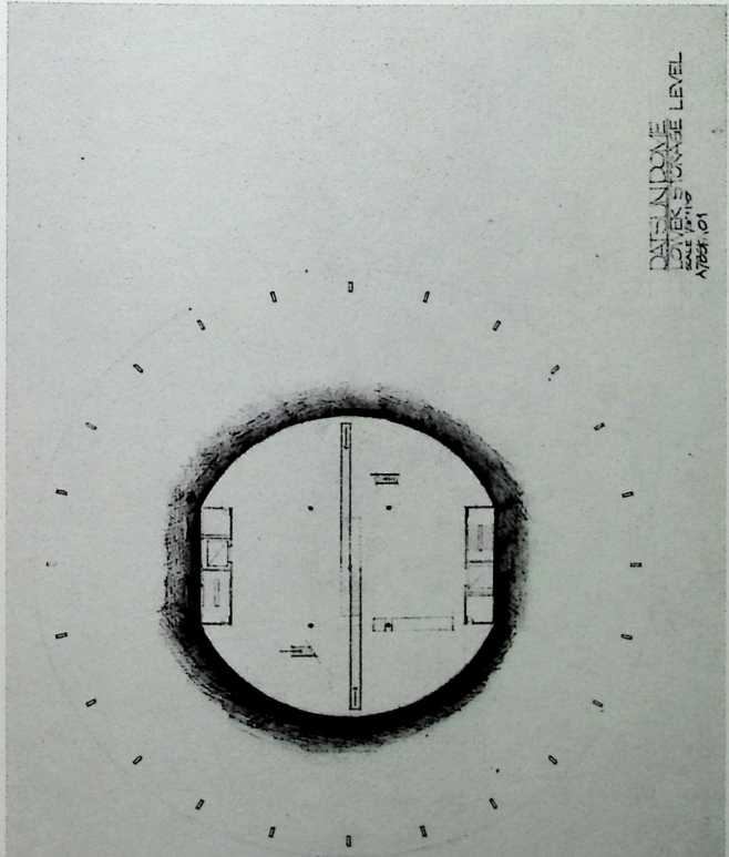
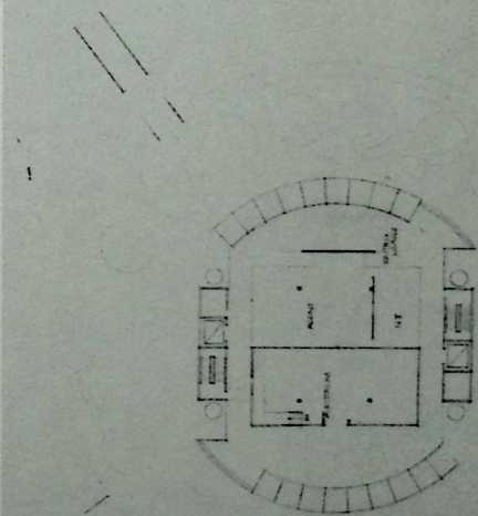
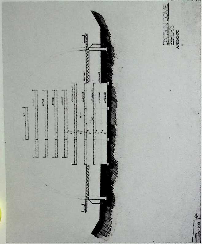
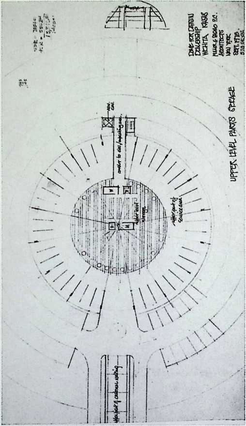
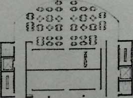
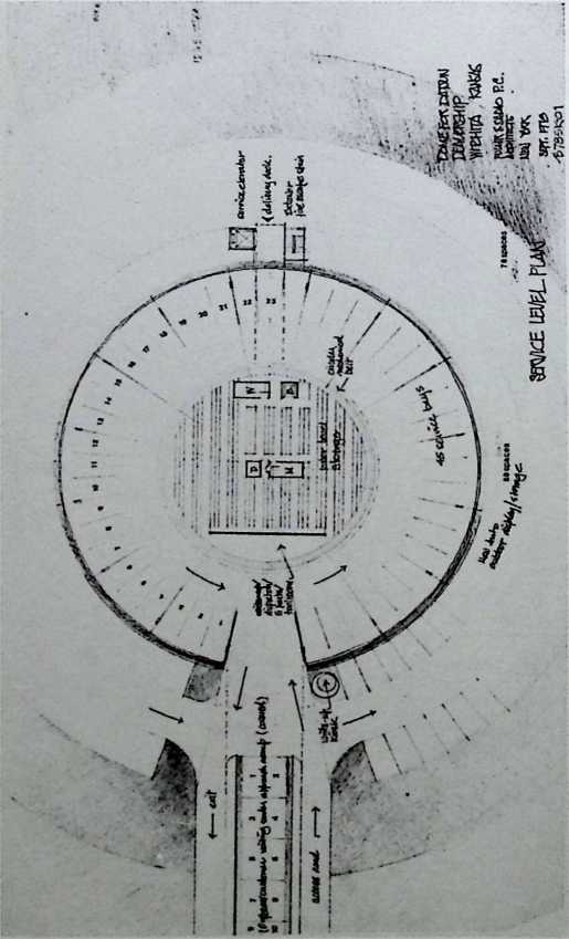
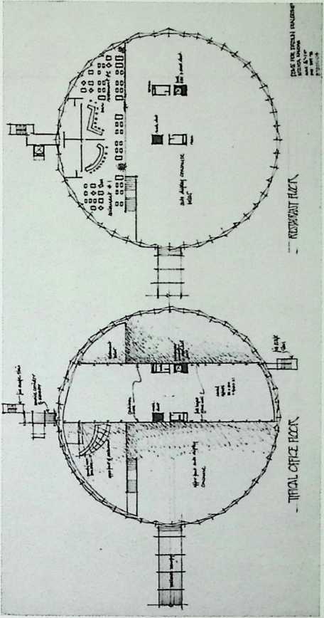
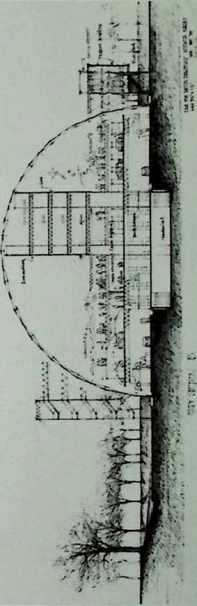
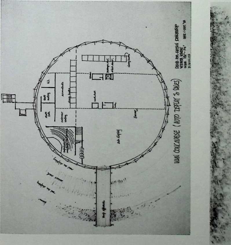
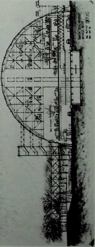
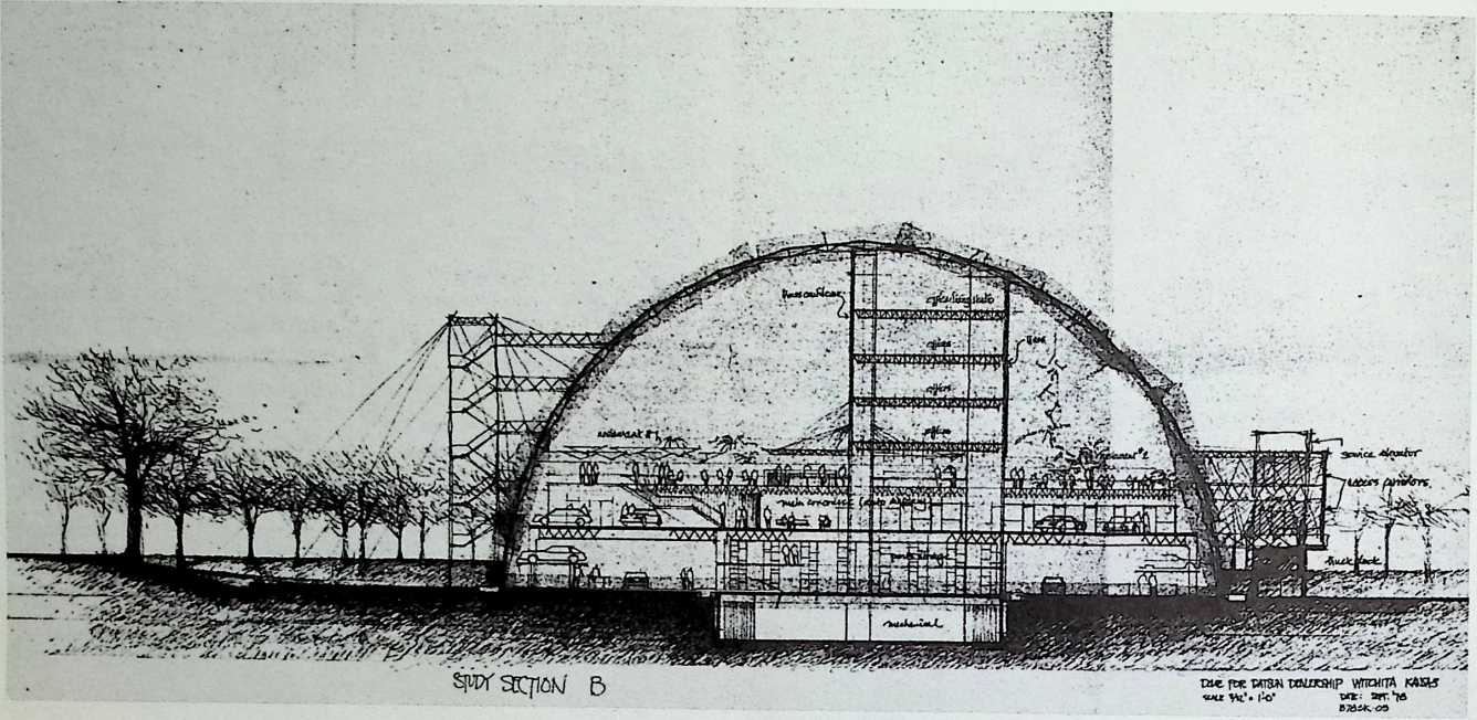
NJ’s Datsun Dome for Wichita, Kansas Fuller & Sadao, 1978
This would have been the first geodesic dome with useful floor space up to the level of the interior apex. The office pavilion within this dome is eight stories high, flanks a service area and showroom, a restaurant, and is accessible via elevator or the vertiginous catwalks of the exterior staircase.
![]()
![]()
![]()
![]()
THE GEODESIC REVOLUTION. PART 2 349
-■-5
![]()
![]()
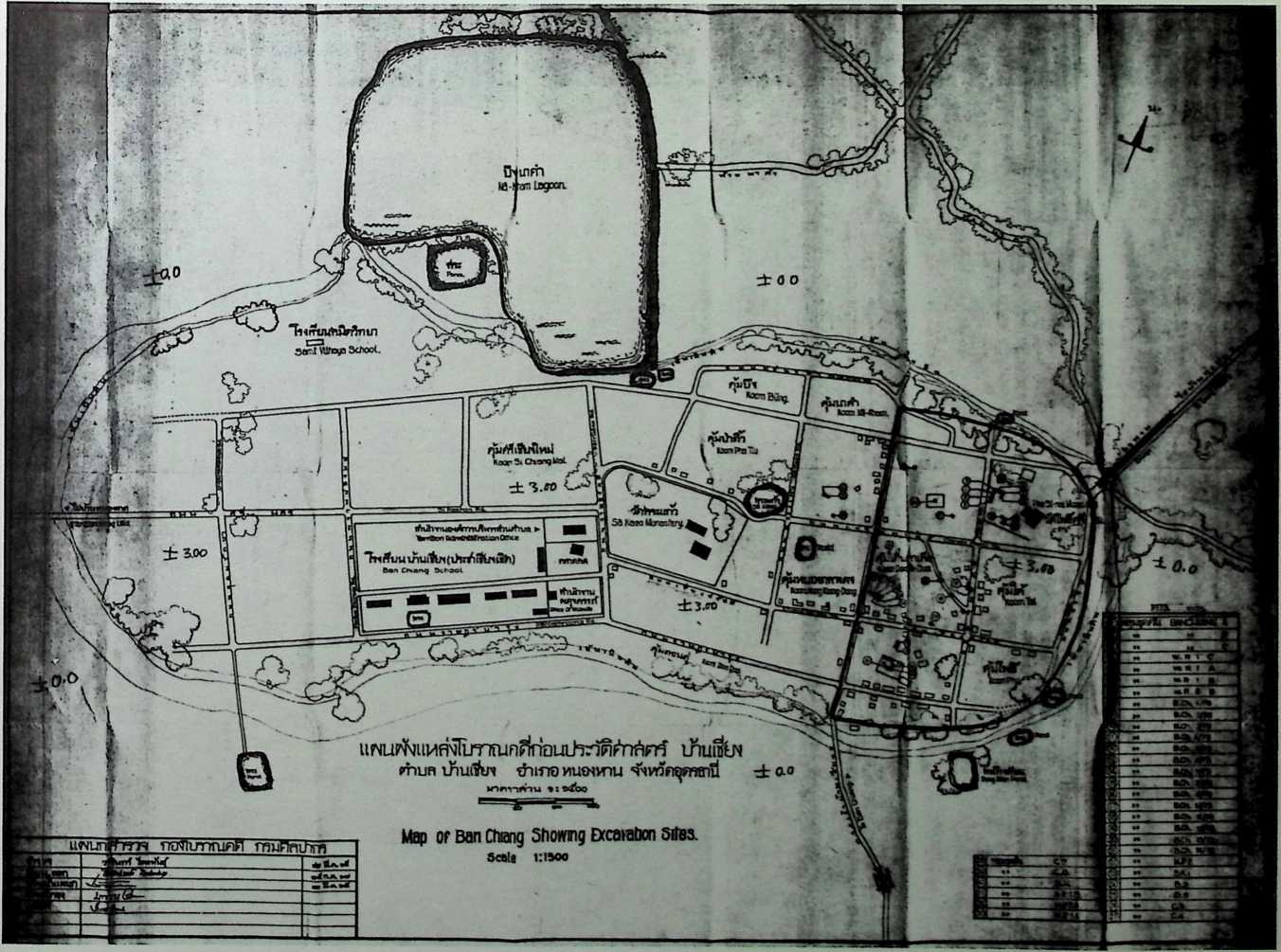
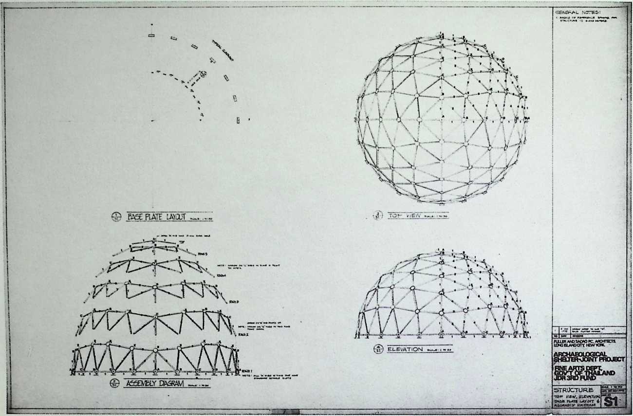
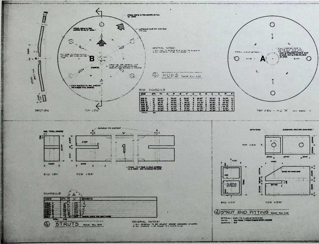
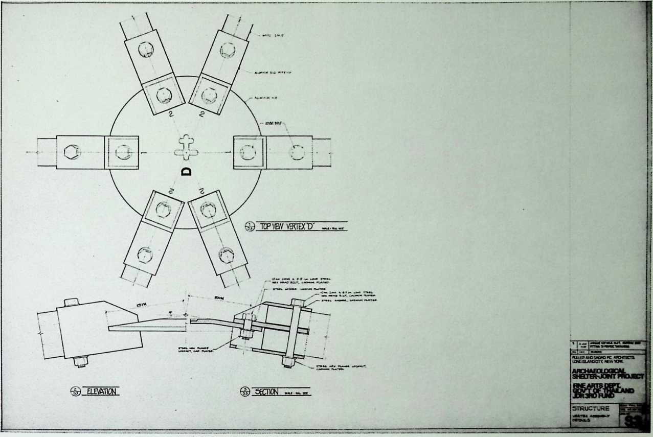
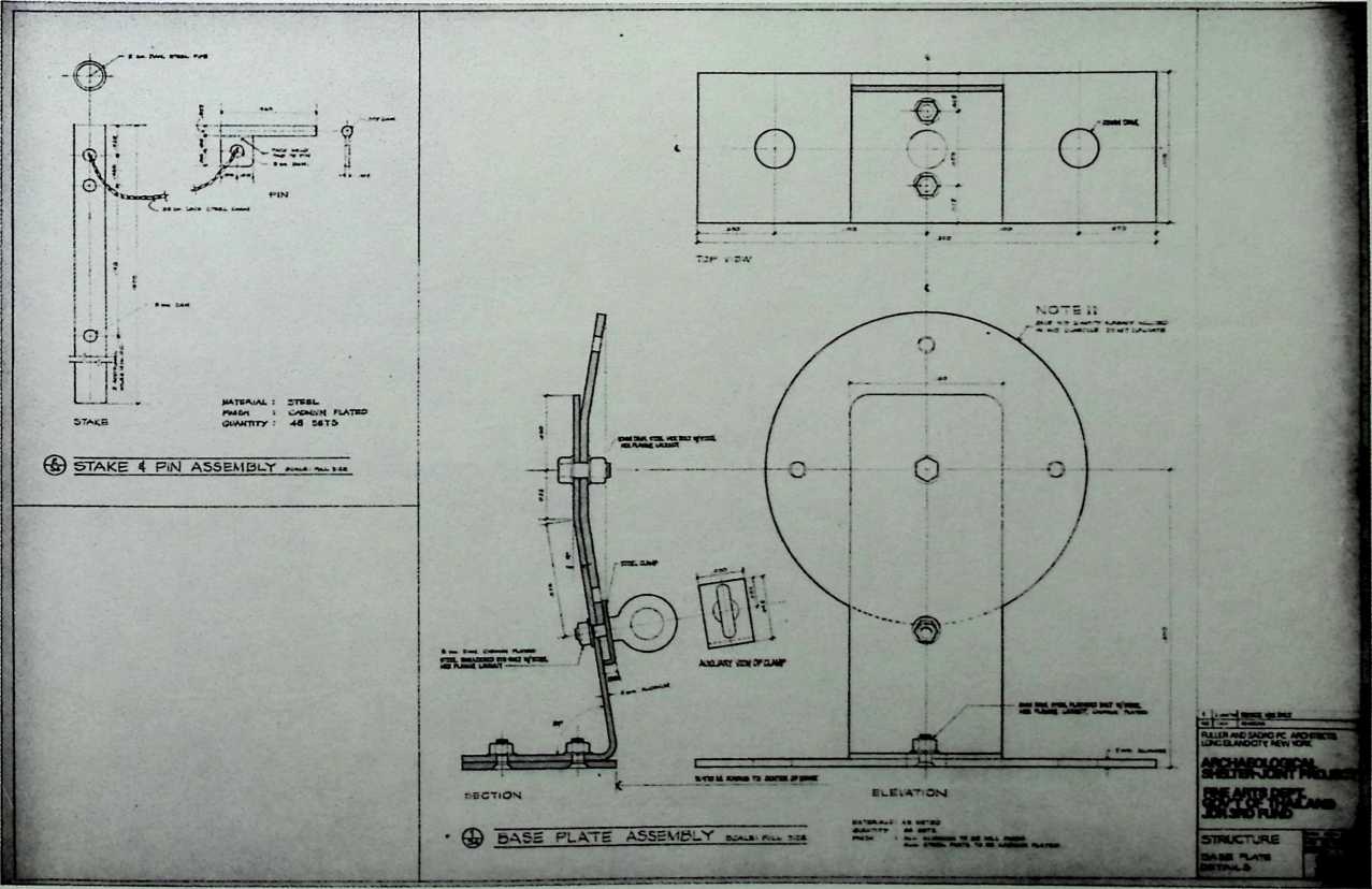
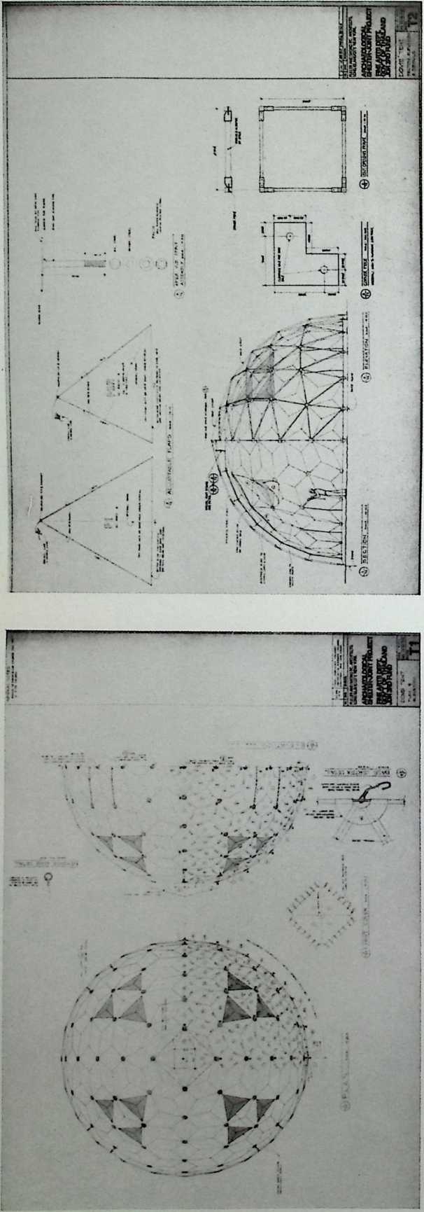
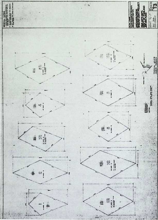
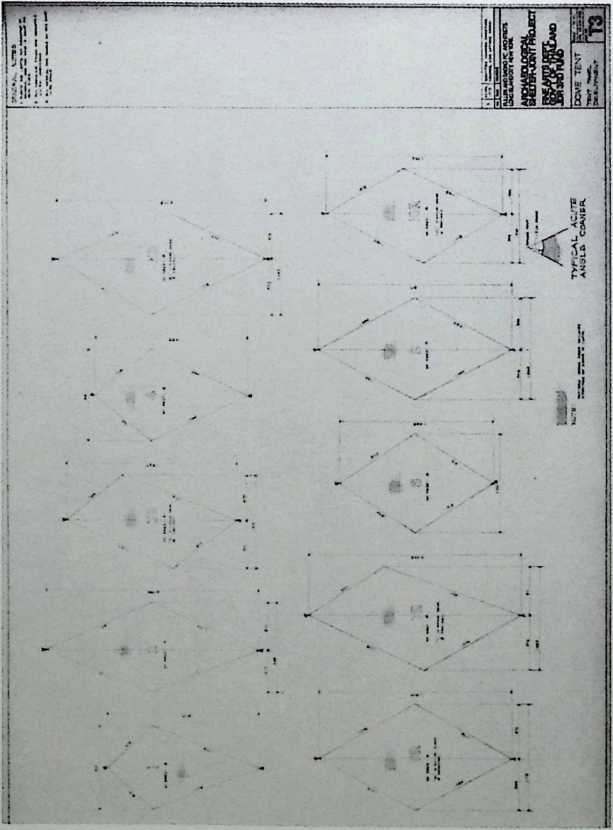
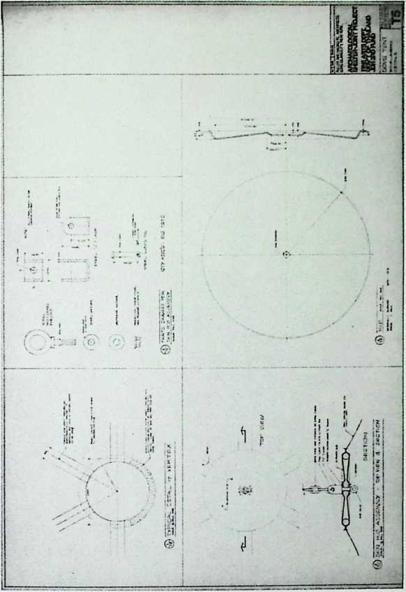
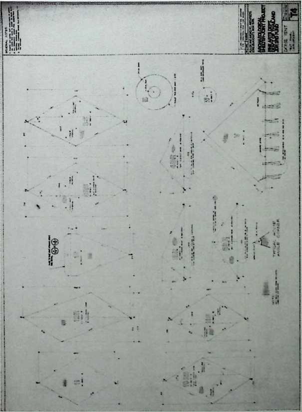
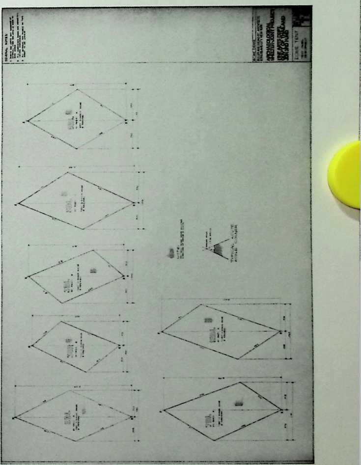
Archaeological Shelter Project at the Excavation Site of Ban Chiang, Thailand
Fuller & Sadao, 1978–1979
The chief function of these small aluminum domes was to keep the sun’s rays from disturbing the archaeologists at Ban Chiang and to protect the excavation site. The open spaces of the aluminum armature were sheathed by individual panels of tent material, some of which had plastic transparent panes to admit some natural daylight.
JOHT HNE ARTS DEPT, GOVT OF THALAND/JDR 3rd FIN) rvusiANDaMMOFCMOtnacra kwwrk dcdwchb dwq W0*/\SPmb ARCHAEOLOGICAL SHELTER PROJECT w™wreJnED0*e. ;

EASE PLATE
HOTBi
J03W FKE ARTS DEPT, GOVT OF THALAMT/JDR 3 FUND ARCHAEOLOGICAL SHELTER PROJECT
"‘‘ ‘‘ASP-3
ARCHAEOLOGICAL SHELTER
JOINT PROJECT:
FINE ARTS DEPARTMENT - GOVERNMENT OF THAILAND
JDR 3RD FUND
BILL OF MATERIALS
FULLER AND SADAO PC - ARCHITECTS LONG ISLAND CITY, NEW YORK
Earth Resources
Observatory, the
Unisphere, Sioux Falls,
South Dakota
Fuller & Sadao (Consultants) and The Spitznagel Partners, Inc.
(Architects and Engineers), 1979
These preliminary studies were done by Fuller & Sadao as consultants for the architects, The Spitznagel Partners, Inc. The interior of the Unisphere would house exhibitions on the theme of ecological building technology. Seventy-seven percent of the air conditioning requires no fuel or electricity.
This floating breakwater can be distinguished from the one Fuller patented earlier by its ability to absorb the energy of the ocean’s waves and convert it to electricity.
[ii] 4,136,994
[45] Jan. 30,1979
Floating Breakwater Patent
1/30/79
United States Patent [i9j
Fidler
[54] FLOATING BREAKWATER
[76] Inventor: Richard B. Fuller, 200 Locust St, Apt. 31B, Philadelphia, Pa. 19106
21.
Appl. No.: 834449
22.
Filed: Sep. 19,1977
51.
1st CL2 E02B3/06
52.
U.S. CL 405/27; 405/63
[58] Field of Search 61/1 F, 1 R, 4, 5, 20
[56] References Cited
U.S. PATENT DOCUMENTS
461.
9/1924 Chase 61/20
462.
6/1971 Oadd 61/1 F
3,590,584 7/1971 Fitzgerald et al 61/1 F
3,863,455 2/1975 Fuller — 61/5
3,969,901 7/1976 Matsudaira et al 61/5
4,023,370 5/1977 Watson — 61/5
Primary Examiner—Mervin Stein
Assistant Examiner—David H. Corbin
Attorney. Agent, or Firm—Parmelee, Johnson, Bollinger
& Bramblett
[57] ABSTRACT
In a floatable breakwater, one or more flexible membranes are suspended below a floatable, open grid. An outer membrane is formed into a trough. Inner membrane components serve to define multiple ports and reduce the energy of the wave as water is moved and churned through the various ports. The inner membrane components may have a truncated tetrahedral configuration. A turbine may be positioned at one end of the breakwater to utilize the wave energy.
19 Claims, 9 Drawing Figures
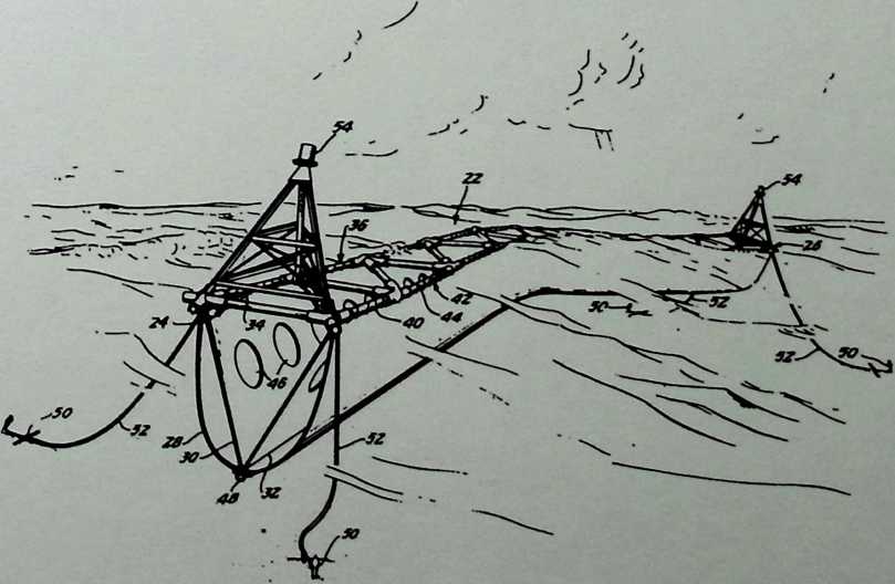
U.S. Patent Jan. 30, 1979 Sheet 2 of 4 4,136,994
U.S. Patent Jan. 30, 1979 Sheet 1 of4 4,136,994
4,136,994
U.S. Patent Jan. 30. 1979
Sheet 3 of 4
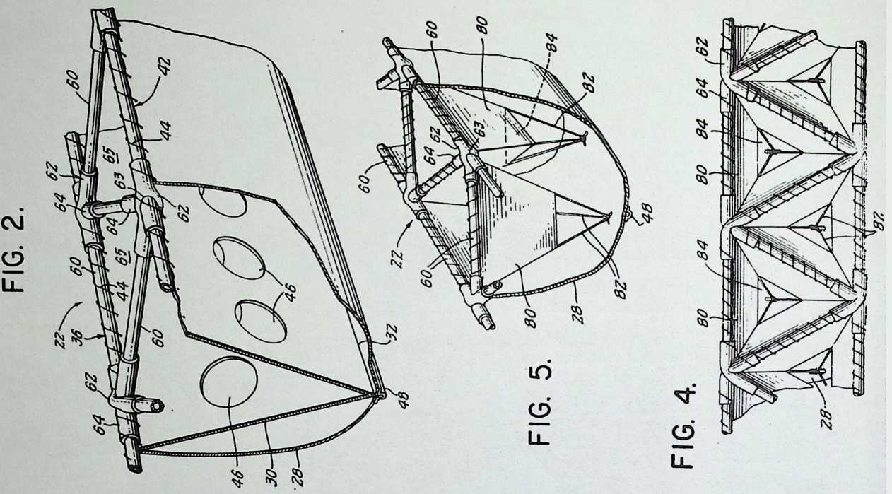
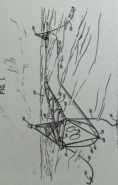
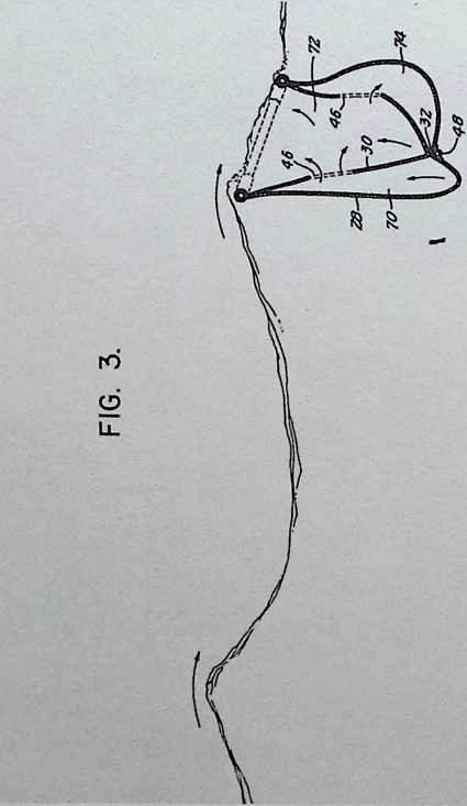
FIG. 6.
FIG. 9.
U.S. Patent Jan. 30,1979 sheet 4 of 4 4,136,994
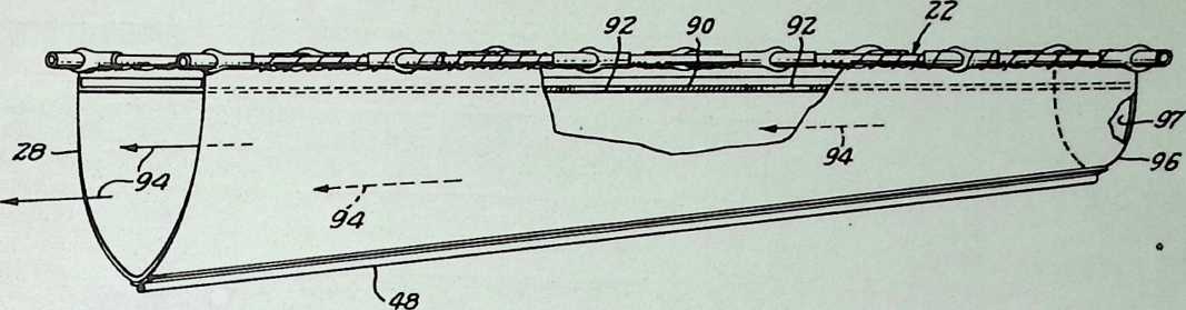
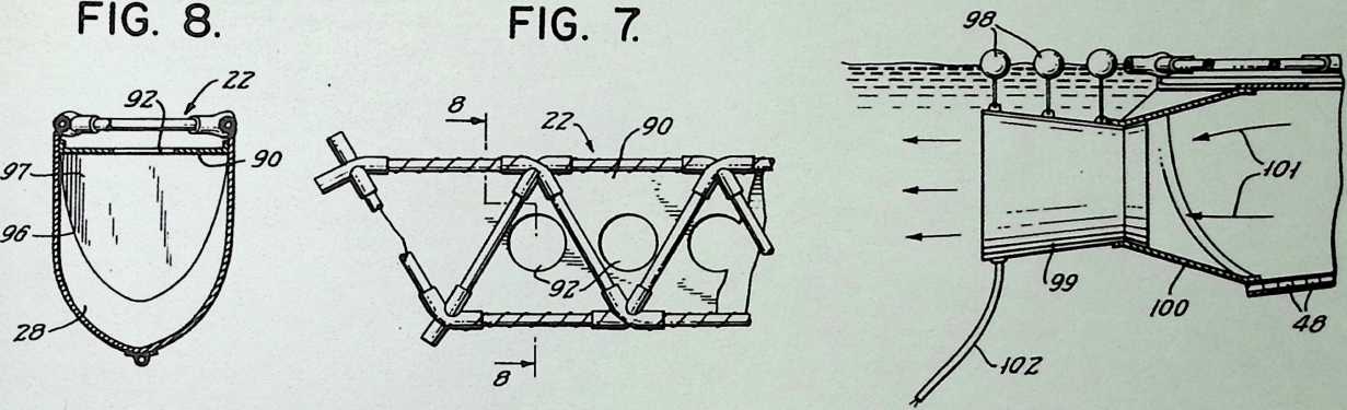
¶ Chapter 37 Restoration of the United States Pavilion, Expo 1967 Fuller & Sadao, 1979
Fuller & Sadao planned to restore the burned pavilion by replacing the acrylic panels with fireproof ones of teflon-coated fiberglass.
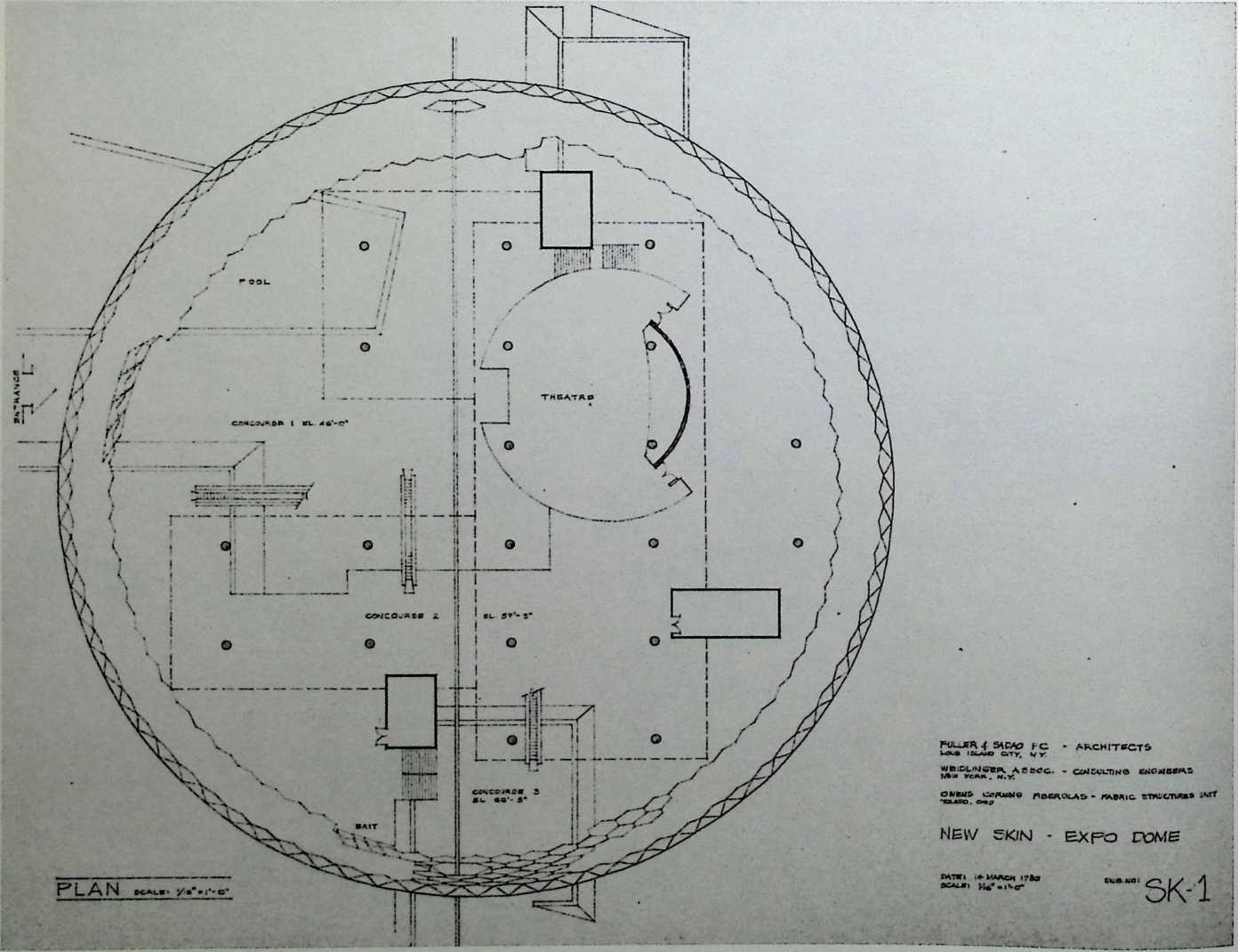
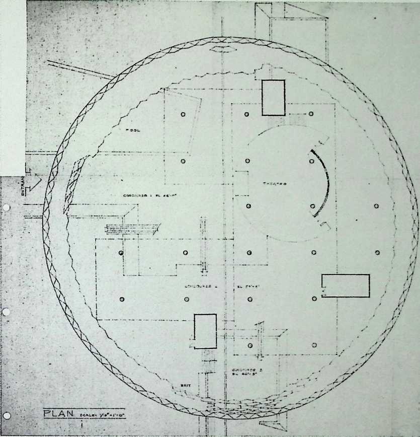
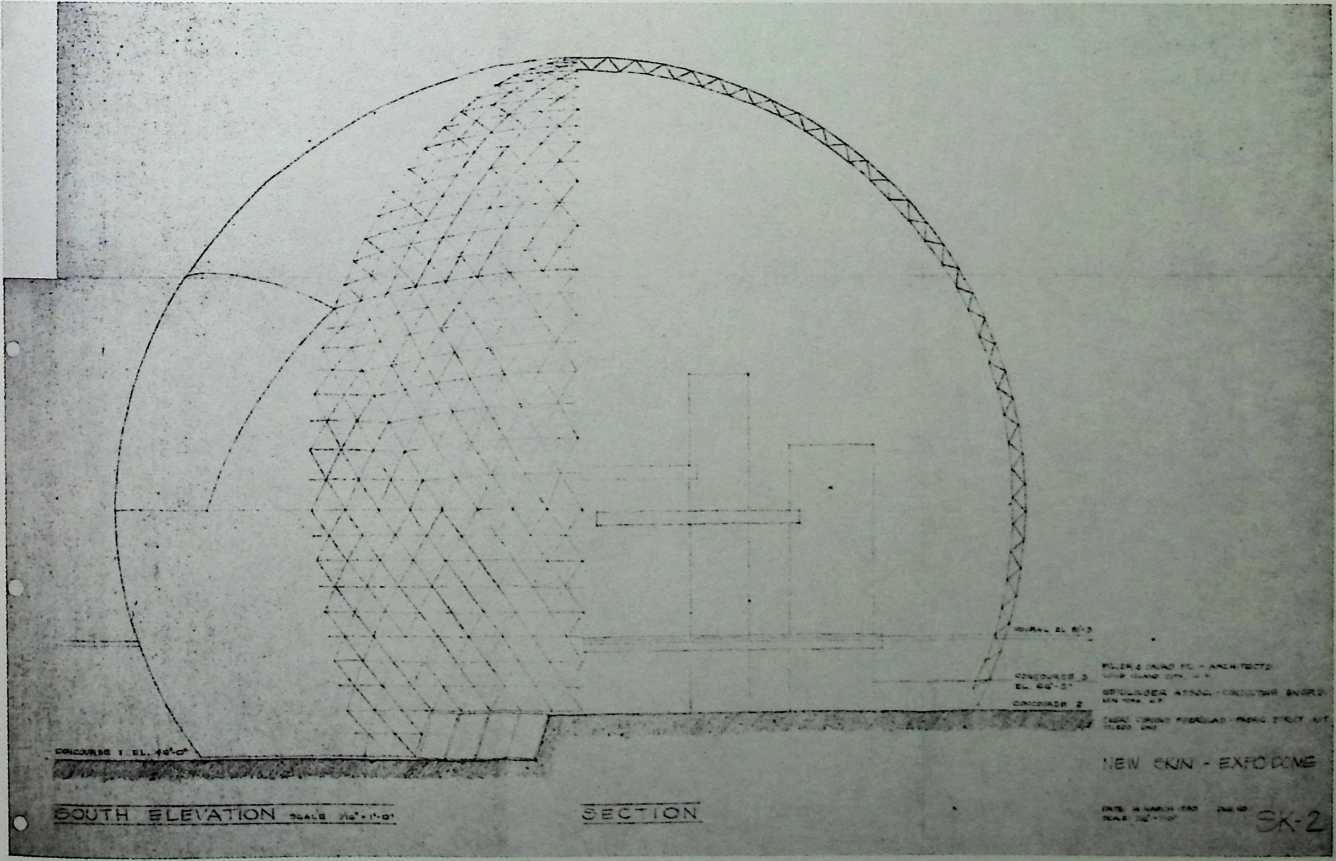
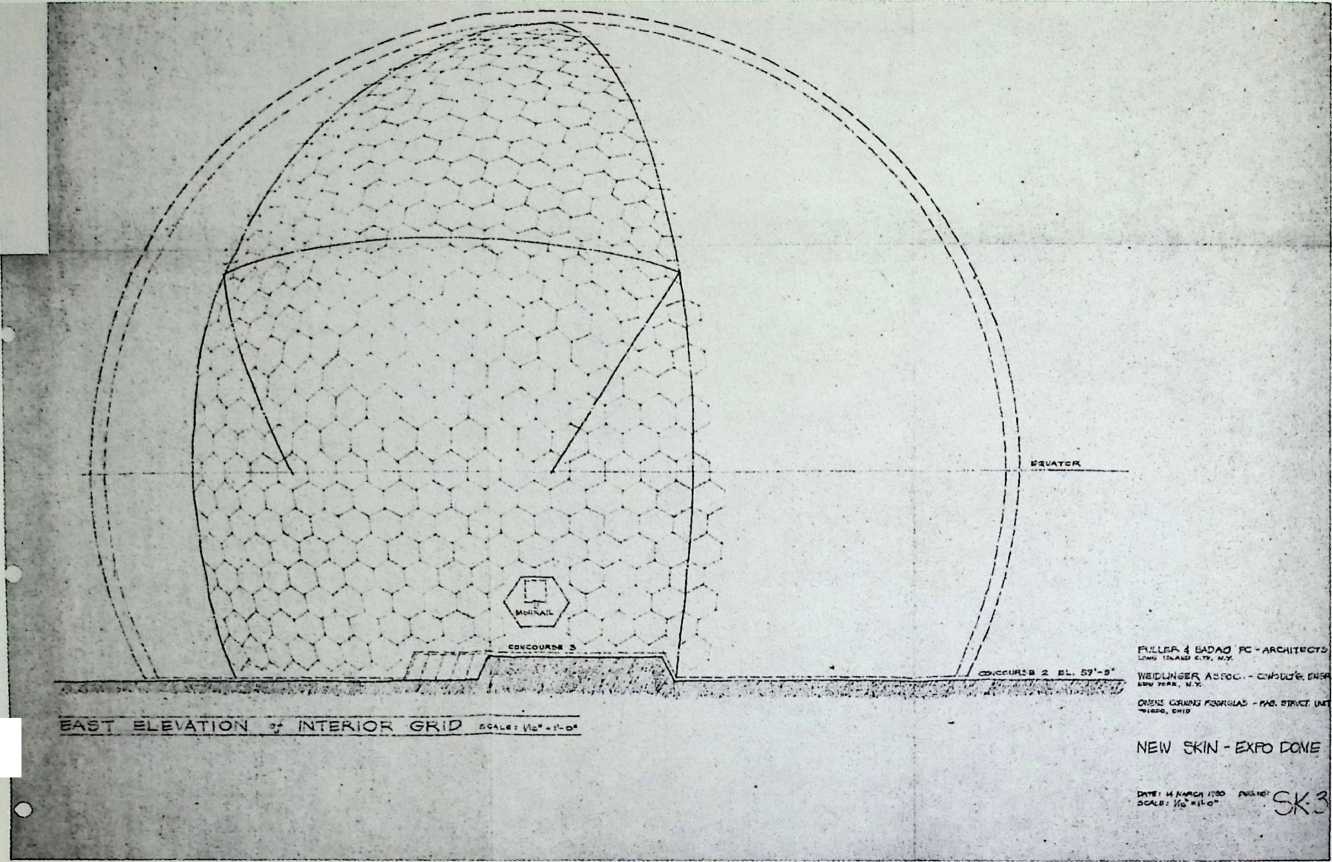
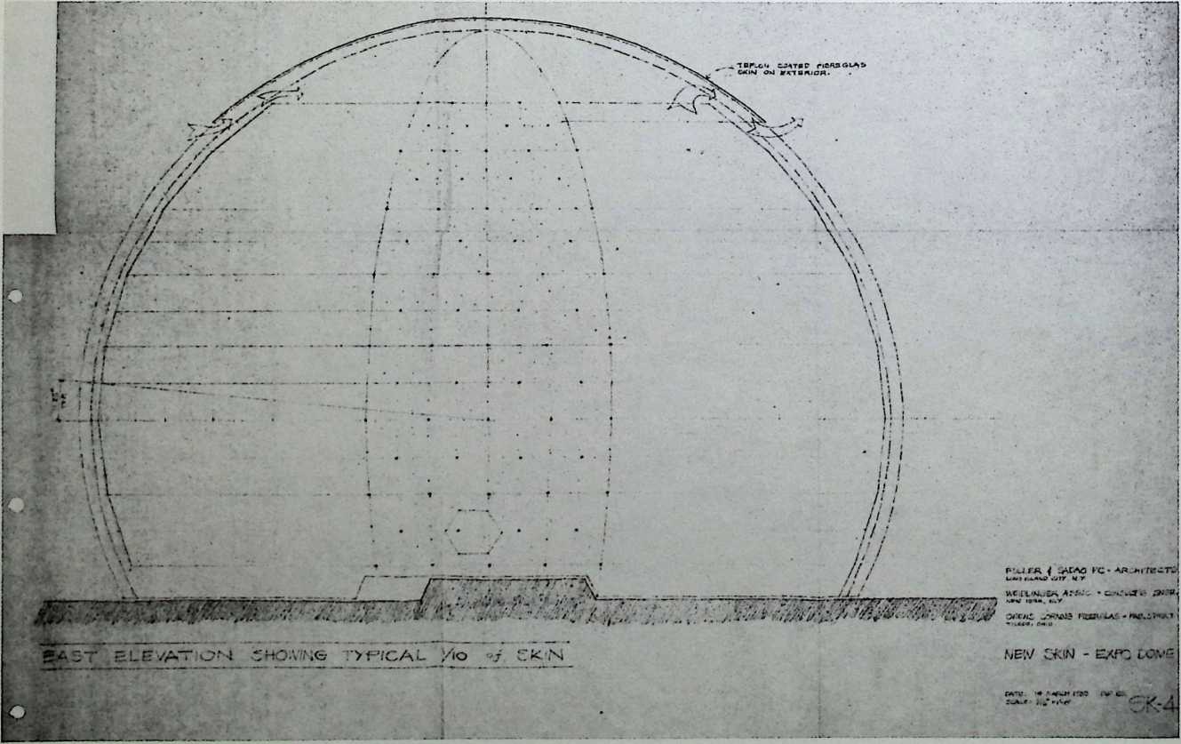
Tensegrity Module Patent 6/17/80
This truss has octahedra, the edges of which are tense cables and the interiors of which are three adjustable crossbeams.
_ - „ip3- ~ >*
United States Patenter- . jin ? 4,207,715/
Ki trick [45] Jun. 17, 1980
[54] TENSEGRITY MODULE STRUCTURE AND METHOD OF INTERCONNECTING THE MODULES
[76] Inventor: Christopher J. Kitrick, 3500 Market St., Philadelphia, Pa. 19104
[21] Appl. No.: 942301
Primary Examiner—Price C. Faw, Jr.
Asirrant Examiner—Carl D. Friedmaif
**Attorney. Agent, or Firm—**Parmelee, Johnson. Bollinger
& Bramblett
[57]
ABSTRACT
[22] Filed: Sep. 14,1978
51.
lot. CL2 EO4B 1/32
52.
US. CX „ 52/81; 52/747;
52/D1G. 10
[58] Field of Search 52/81, DIG. 10. 747
[56] References Cited
U.S. PATENT DOCUMENTS
3.063,521 11/1962 Fuller — 52/81 X
3.354,391 11/1967 Fuller — 52/581 X
A tensegrity structure is- formed from a plurality of interconnected tensegrity modules. Each module includes several column-like compression members and tension elements run between ends of the compression members to define a polyhedron. The tension elements form the edges of the polyhedron and intersect at the vertices of the polyhedron. The interconnected modules are joined to each other with triangular faces abutting but with the edges and faces of the abutting triangular surfaces of the respective modules rotated 180* away from superposition and with the vertices joined to tension element edges, being joined at a point located one- half or one-third of the way along the length of such
FOREIGN PATENT DOCUMENTS
edge.
7 Claims, 17 Drawing Figures
659780 I/I964 Italy 52/608
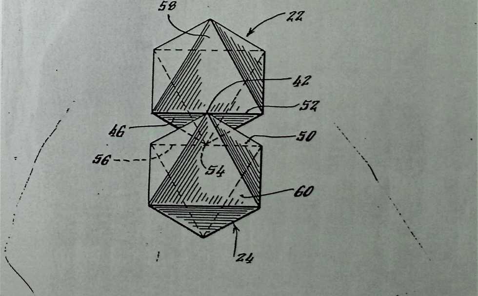
UrS.-Patent—Tun. 17. 1980 ‘‘ ’ Sheet 2 of 6 4,207,715
mjL-Patent Jun.-F7.-198O Sheet 4 of 6 4,-207,715
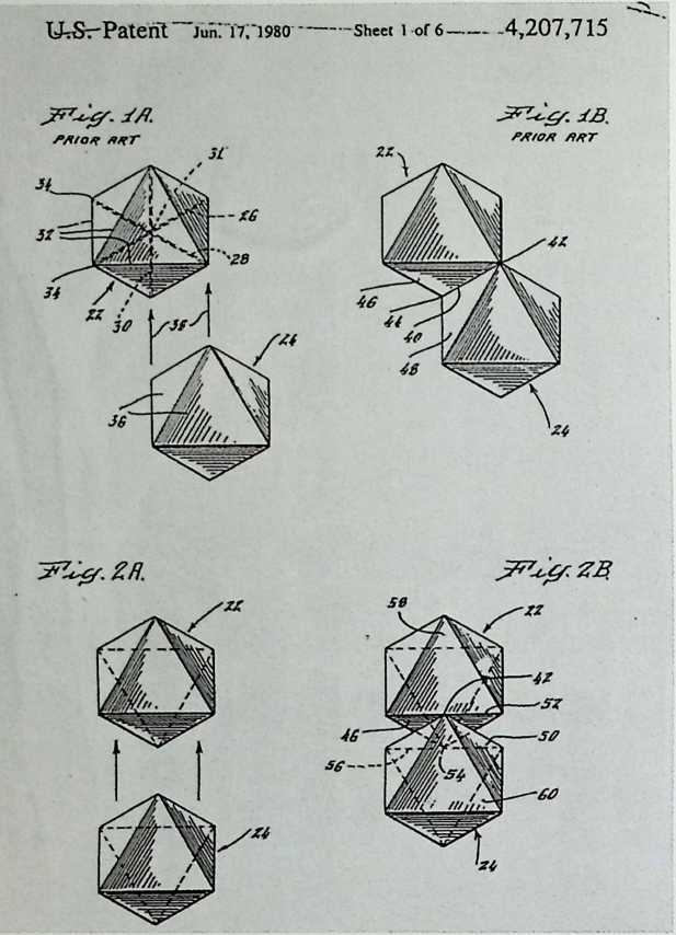
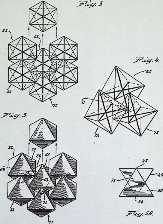
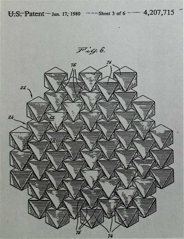
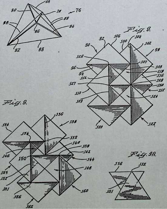
**UtS—**Patent Jun. 17, 1980’ Sheet 5 of'6 4,207,715
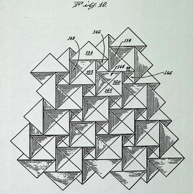
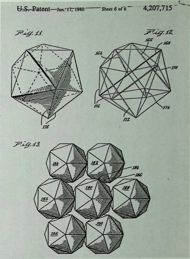
Jitterbug Sculpture, University of Akron
Fuller & Sadao, 1979–1980
The Jitterbug is a sculpture based on the vector equilibrium principle developed decades earlier. It has three phases: icosahedral, octahedral, and tetrahedral.
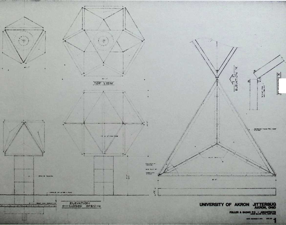
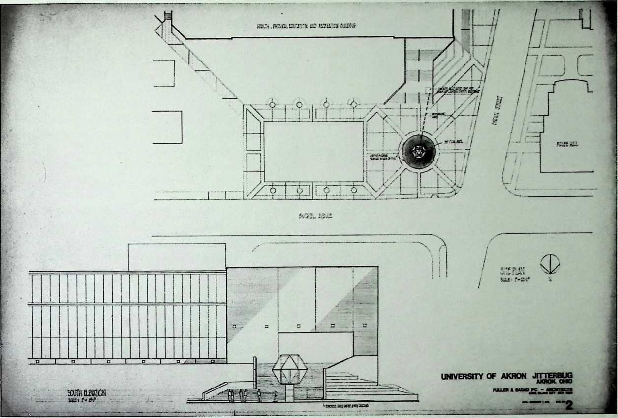
Lotus Dome, Penang, Malaysia Fuller & Sadao, 1980
Fuller & Sadao, in collaboration with Architects Team Three, designed a fly’s eye geodesic dome to house the monumental cult statue of Kuan Yin. One hundred sixty-seven feet in diameter, this transparent structure houses terraces, a lotus pond, a kitchen, restrooms, in addition to a hall in the base of the statue. Kuan Yin faces east over a lotus pond, which stretches beyond the base of the dome to the outside. Pilgrims would have been able to park their cars in a specially designed lot and would have reached the pergola-covered east entrance via a ramp. Beyond the vestibule, they would have ascended first to a bifurcating staircase to the level of the statue’s lotus base and then to two viewing galleries. This unexecuted idea is important because it explores the possibility of inexpensive and aesthetically harmonious shelter for artifacts on a monumental scale.
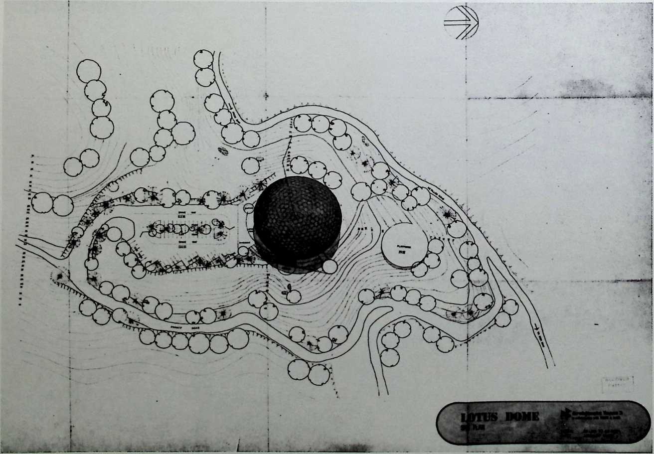
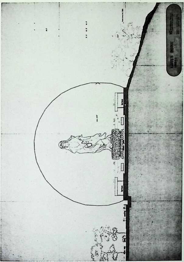
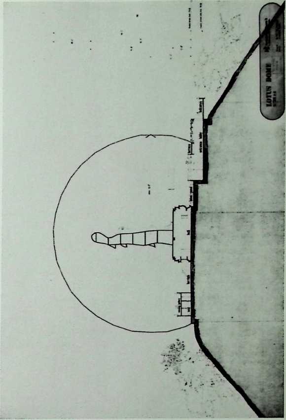
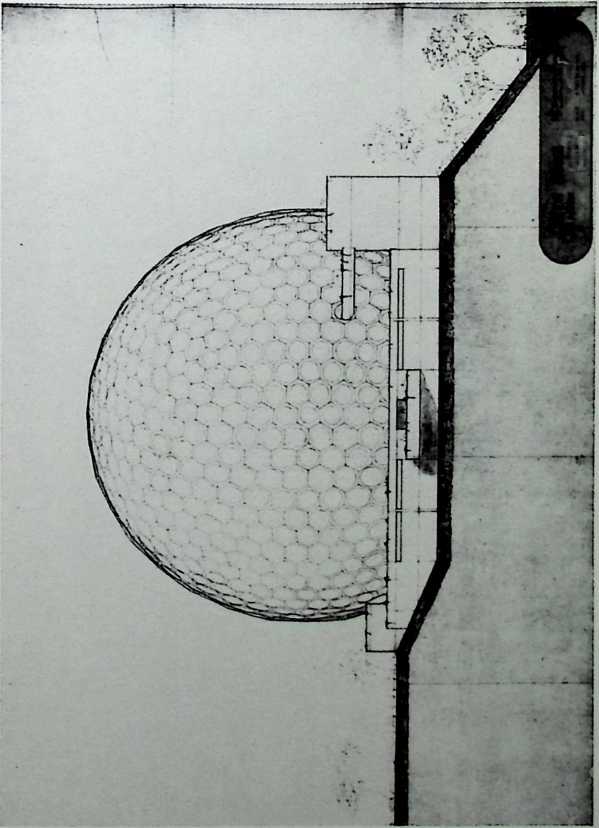
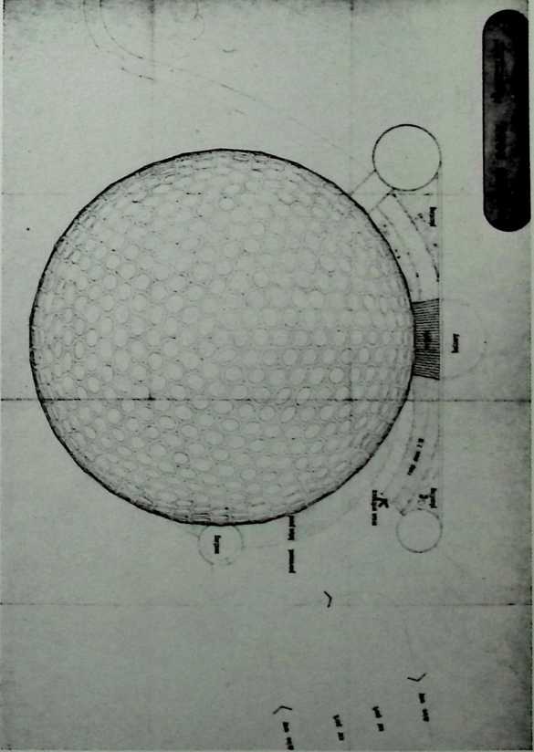
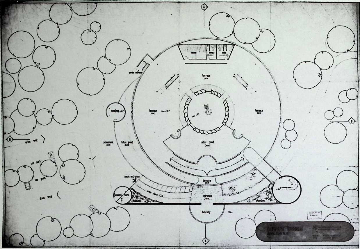
4V Parallel Sheet-Metal Dome Fuller & Sadao, 1980
The lower half of this sheet-metal dome is of parallel ‘‘truncatable’’ sections, although the upper half conforms to a ‘‘triacon’’ grid. The ‘‘triacon’’ grid was developed by Duncan Stuart during the early fifties; and structures based on this grid are theoretically more stable, as the constituent panels conform to the thirty-one great circles. With the use of this grid, one has the smallest discrepancy in the sizes of individual panels. By contrast, the ‘‘truncatable’’ grid is necessary to ensure that a dome touches the ground on the points of evenly spaced triangular sections of equal size. Although this sheet-metal structure provides a clear illustration of the triacon-truncatable combination, the most famous example of this structure is the United States Pavilion for Expo ‘67, the lower third of which is composed of truncatable sections.
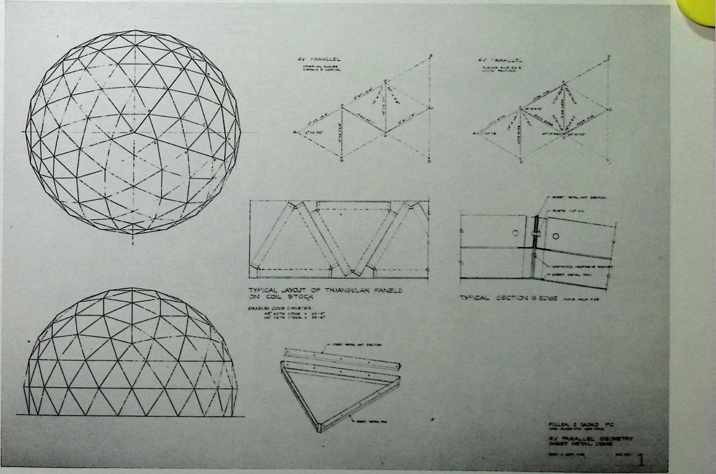
Hanging Storage Shelf Unit Patent 3/22/83
The equal pull of a vertical, rectangular shelf on three ceiling bolts attached to six overlapping support cables produces a hovering piece of furniture accessible on all of its four sides. It actually becomes more stable as the weight of its load is increased. (See Dymaxion Victrola Agents Record Library, Volume One.)
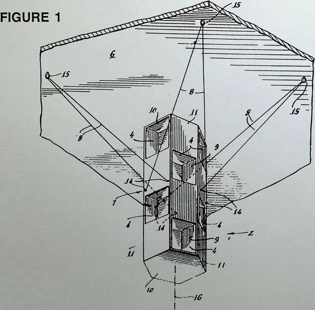
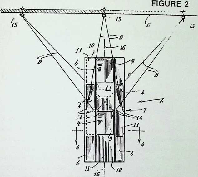
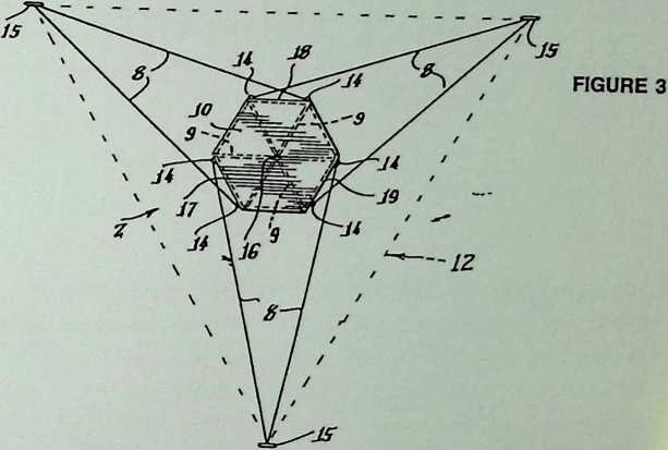
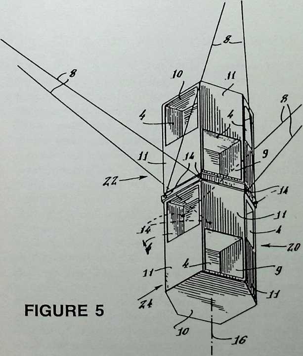
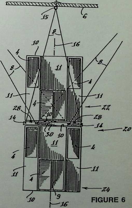
Appendix: Working with Buckminster Fuller
by Don L. Richter
It was my privilege to study with R. Buckminster Fuller in 1949 at the Institute of Design in Chicago. It was ‘‘Bucky’’ who first stimulated my interest in the development of new structural systems. He also made me aware that to continue to build structures with slow, inefficient technology with a huge waste of precious raw materials was a luxury society could no longer afford: the impact of man on his environment is becoming more important than the impact of the environment on man. Fuller faced such issues during his early studies of great circle and geodesic dome geometry. These developments were concerned primarily with dome framing techniques, and, more particularly, with the geometry of such frames (Figure 1).
THE EARLY WORK OF D. L. RICHTER
It was my conviction, that while a geodesic framing system had many advantages from the standpoints of structure and production, it represented only part of the enclosure solution. Given a good structural dome frame, some form of cover is still required to make it a shelter enclosure. Furthermore, if this cover, or skin, is made tough enough to act as a secure barrier between interior contents and exterior environment, it might also be used to carry a share of the structural burden. I reasoned that if it were shaped properly, the skin might replace the frame totally and become the complete structure.
This concept led to a series of independent studies on the effects and factors involved in compound curved shell shapes. The research studies expanded to include many different forms of shaped surfaces, such as non- spherical domes, involute and hyperbolic paraboloid shells, as well as many other shapes without names (Figure 2). These dome models are indicative of the early research into compound-curved shapes developed in 1949.
It was recognized that while such research discoveries are vital, it is equally important to develop them into real products for a real world. This pioneering design work has resulted, over the past twenty-five years, in many dome structures that are being used throughout the world, from Alaska to the Antarctic. The first opportunity to employ these new stressed-skin principles combined with a space truss system and geodesic dome geometry came in 1956, when I was with the research and development division of Kaiser Aluminum. The problem posed was to design and fabricate a 150-foot dome of all aluminum construction for erection in Hawaii.
The structural system of space truss and stress-skin development for the Hawaii Dome Project (Figure 3) was patented and erected by Kaiser Aluminum. The first of many such domes was designed for the Hawaiian Village Convention Center built in 1957. Several years were required to develop the Hawaiian geodesic dome structures for use in more severe climates. To facilitate their realization, we designed permanent tooling and trained personnel in the new construction techniques.
TEMCOR DOMES
Following the success of the Hawaiian projects, I formed Temcor with two others in Torrance, California. Temcor was fortunate to have R. Buckminster Fuller as a member of our board of directors until his death in 1983. In Torrance, we designed a full line of pentagonal and hexagonal geodesic domes in sizes up to 232 feet in diameter. Our success in the myriad problems related to design fabrication and erection is perhaps best exemplified by the construction of a triple geodesic dome sports complex in 1973 in upstate New York. It comprises an interconnected cluster of three hexagonalshaped domes, each having a clear span of 232 feet and a height of 62 feet at the apex.
The more than 33,000 gold-anodized aluminum panel and strut components for the three domes were engineered and fabricated to precise tolerances at Tem- cor’s manufacturing plant in Torrance and shipped to Elmira, New York, for assembly. They were erected at ground level around the base of a lifting tower and raised into place (Figure 4). After a dome was totally assembled around the tower, it was hoisted and secured to previously prepared supports, and the lifting tower was then removed (Figures 5 and 6).
It is rather significant that aluminum geodesic domes designed and manufactured by Temcor have been selected in competition with nongeodesic domes of steel, concrete, wood, and fiberglass plastic—an excellent proof of the coordinated design, fabrication, and erection indicated by Bucky Fuller many years earlier.
Temcor also manufactures two other types of patented dome structure that employ geodesic great circle geometry: the Crystogon structures and PolyFrame domes, each of which has its own unique applications.
TEMCOR CRYSTOGON
/ Crystogon domes employ triangular panels of acrylic secured to a framework of extruded aluminum. The transparent or translucent plastics are nonstructural; they do not carry loads from the aluminum dome frame. The inherent stiffness of the geodesic frame has been proven to be particularly important for this product.
Unlike the Expo 1967 dome in Montreal, Temcor Crystogon domes have a single layer geodesic framing plan, yet they can be built in spans up to 250 feet.
Temcor Crystogon domes are now employed in a variety of applications including arboretums and aviaries, skylights in restaurants, all-weather swimming pool covers, and other public buildings. Perhaps the most dramatic Crystogon installation to date is the 150- foot diameter Tropical Botanical Center Exhibition Building in Des Moines, Iowa.
TEMCOR POLYFRAME
In contrast to the Crystogon, the Temcor PolyFrame dome employs wide-flange beams of extruded aluminum that are covered with flat, triangular aluminum panels. As with the Crystogon, the nonstructural panels are designed primarily to provide protective covering and contribute only secondarily to the strength of the dome frame.
The PolyFrame domes are widely used for bulk storage covers, wastewater treatment plants, sports facilities, and special structures such as the famous South Pole PolyFrame and Long Beach Spruce Goose domes. Its advantage as a tank cover is obvious when one considers that a concrete dome for a typical 150- foot diameter tank weighs about 360 tons. A steel cover for the same tank weighs about 175 tons. But an aluminum PolyFrame dome weighs only 18 tons—just five percent of the concrete and ten percent of the steel ones. Part of this efficiency is the direct result of using geodesic geometry.
DOME GEOMETRY COMPARISON
To illustrate the merits of geodesic structures, one could compare them with the computer analyses of three other dome framing systems. In this assessment, all four domes were made as nearly equal as their individual geometries would permit. All four domes analyzed had the same base diameter, the same spherical radius, and the same number of gusset, or nodal, points interconnected by struts following their four different geometries: geodesic, lattice, Lamella, and Schwedler (Figure 7).
A true geodesic geometry does not employ concentric lesser circles. This is the key feature to look for when determining whether the dome geometry is fully geodesic. The great circle arcs in the geodesic dome example of the accompanying figure extend from the base ring on one side of the dome to a corresponding point on the other side. The space truss formed by the three sets of intersecting great circles yields surprisingly uniform, almost equilateral triangles.
The plan view of the lattice geometry dome has framing struts that follow intersecting, spiral-like patterns that connect the base ring to the concentric inner rings and the apex of the dome. None of the framing lines in the lattice dome follows a great circle arc.
A typical Lamella geometry also has horizontal lesser circles concentric with the base ring. The Lamella dome has an advantage over the previous two systems, because the clutter of members intersecting at the apex has been reduced. The triangles formed between rings and struts are also more nearly equal in size.
In the plan view geometry of the Schwedler, or radial rib, dome, you will notice that a group of frame members extend from the base tension ring to the apex in great circle arcs. The base ring and the three concentric inner rings are lesser circles. Virtually all the commonly used nongeodesic dome frame systems have a number of such lesser circles in concentric rings. In the Schwedler dome, the diagonal framing members required to stabilize the dome have been shown as dashed lines. These diagonals are required to make the dome a completely triangulated three-dimensional space truss.
Although other geometric configurations and variations have been studied, these four basic types are the most representative. For our computer analysis of the four types, the following equalizing criteria were used:
1.
All domes are the same overall size—that is, 100 feet in diameter and 14 feet high.
TABLE 1
Schwedler Radial Rib
|
Lattice
|
Lamella
|
Geodesic
|
||
Without Diagonals |
With Diagonals |
||||
Weight in pounds |
10,000 |
10,000 |
10,000 |
10,000 |
10,000 |
Number of nodal points |
|
|
61 . |
61 |
61 |
Max. uniform load p.s.f. evenly distributed |
|
|
25 |
32 |
45 |
Max. unbalanced load p.s.f. right side |
|
|
20 |
28 |
40 |
p.s.f. left side |
|
|
10 |
14 |
20 |
Relative strength with unbalanced load |
|
|
50% |
70% |
100% |
Inches deflection with unbalanced load of 12 p.s.f. and 6 p.s.f. |
|
|
|
% |
% |
2.
All domes have sixty-one nodes (strut connections).
3.
All domes used tubular struts of the same diameter to make up the frame.
The results of our computer analysis are shown in Table 1. Although the Schwedler dome without diagonals looks rather good under uniform symmetrical load, the unbalanced loading caused by simulated snow and wind is far more important. Under such loading, the Schwedler dome without diagonals would only support 12 p.s.f. on one-half the dome, with six pounds distributed over the other half. By adding the diagonals to the Schwedler dome, its strength was more than doubled. This increase in strength was accomplished by reducing the tubular frame wall thickness and without increasing the total weight of the dome.
The lattice dome will support 20 p.s.f. under the unbalanced condition, the Lamella, 28 p.s.f. By contrast, the geodesic configuration will support a full 45 p.s.f. as a symmetrical load over the total surface, or a nonsymmetrical loading of 40 p.s.f. on one side and 20 p.s.f. on the other.
SOUTH POLE POLYFRAME
A special application of the PolyFrame dome, and one that has received worldwide attention, is the U.S. Navy’s South Pole Station. This huge, all-aluminum dome is 50 feet high and 164 feet in diameter, and serves as a giant weather break to protect the Navy’s science headquarters, communications center, and crew’s quarters (Figure 8).
The lightweight Temcor dome was selected for this difficult task because it could be broken down readily into coded components for air shipment and assembly under frigid working conditions. Moreover, the PolyFrame dome is inherently capable of withstanding heavy winds and drifting snow. The South Pole Dome was designed to withstand winds of 125 miles per hour, uniform loads from ten feet of snow on top and, even more importantly, unbalanced loadings of thirty feet of snow on one side (Figures 9 and 10).
POLYFRAME COVERS THE GOOSE
Probably the most significant verification of geodesic efficiency in dome structures is the Temcor PolyFrame dome erected to house and exhibit Howard Hughes’ Spruce Goose aircraft in Long Beach, California. Housing without damaging the world’s largest wooden airplane of World War II vintage presented some very’ difficult structural and logistics problems. The Spruce Goose has a wing span of 320 feet and a tail section that stands 100 feet above the ground. The Temcor dome was selected to be the permanent home of the flying boat instead of steel, wood, concrete, or fabric structures. The PolyFrame dome, including its foundations, saved the builder well over a million dollars—a great verification of the fact that quality need not be sacrificed to reduce costs when good design and geodesic principles are employed.
The 415-foot-diameter aluminum dome required to house the flying boat rests directly on the foundation at ground level and rises 130 feet at the center to clear the aircraft (see Figures 11—14). Unique erection procedures were required to realize this dome. Notice the large temporary’ opening left in the side of the dome to allow passage of the flying boat. One view clearly shows the special geodesic geometry as modified for the construction requirements (Figure 15).
Bucky Fuller expressed to me complete satisfaction with the design during a visit to the site of the Temcor Spruce Goose dome (Figure 16). The dome represents the state of the art in efficient structures, as it requires only 0.75 ounces of material per cubic foot of enclosed volume.
These and other construction concepts brought forth by Bucky Fuller will become more feasible with each passing day. My work and success with Temcor is only a beginning.
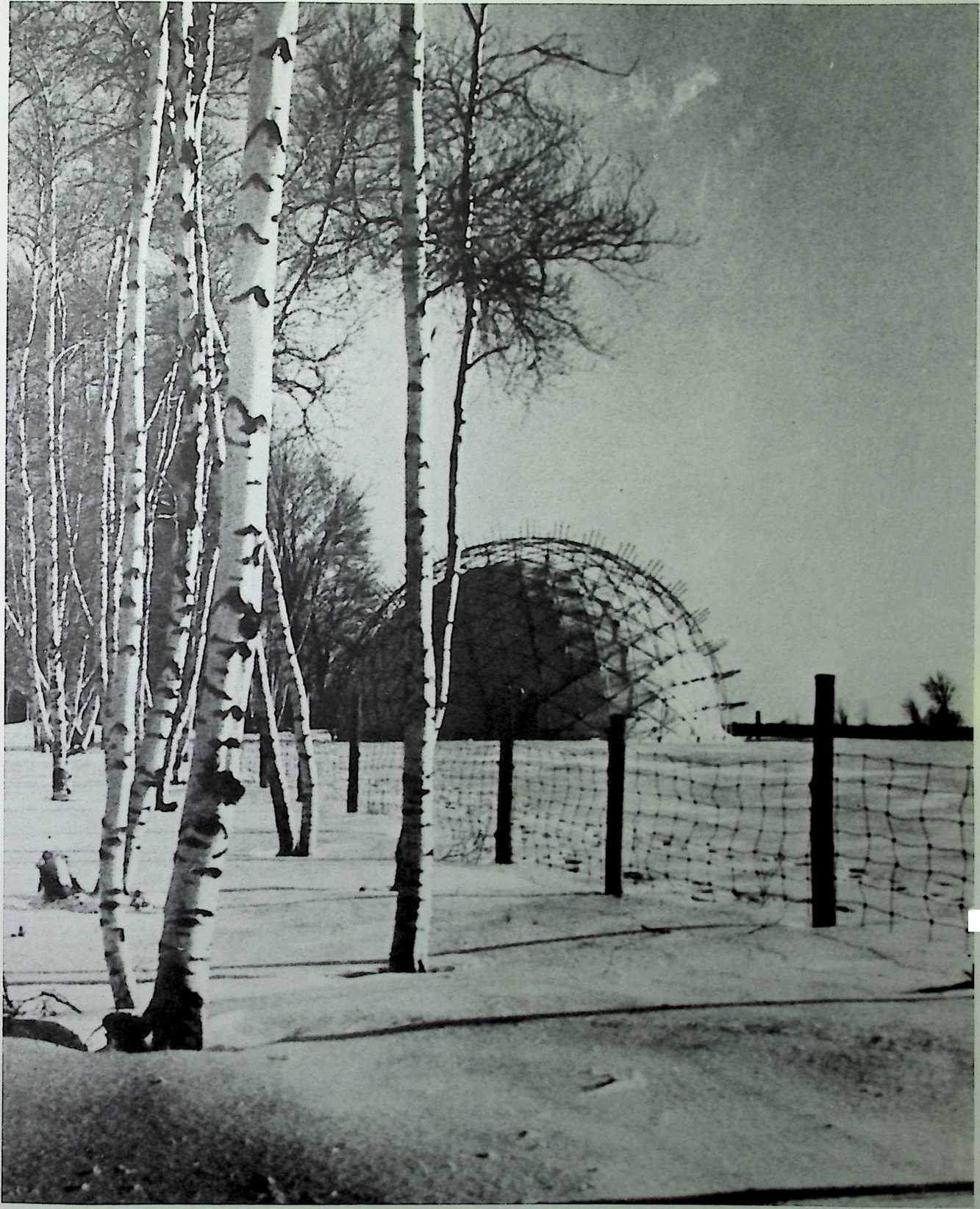
Figure 1. The forty-nine-fool-diaineler structure best illustrates some of the early geodesic geometry frame domes. Il was designed and erected by Jeff Lindsay in Canada in 1949. This prototype shows the ‘‘sprit-truss’’ method of stabilizing gusset points to prevent individual gussets from snapping through.
•t :
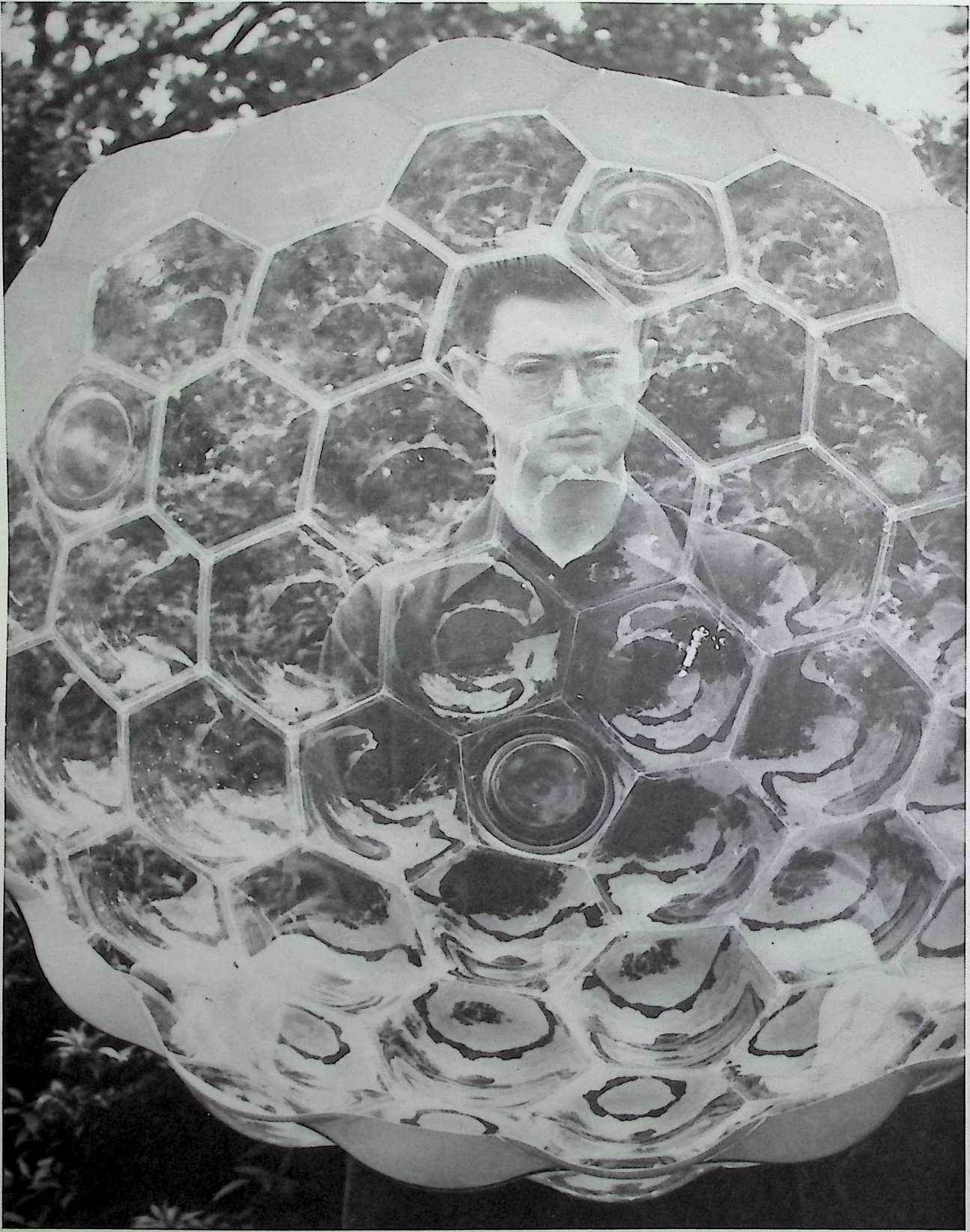
Figure 2. The model shown here is the first involute dome system. It is one of several types developed in 1949.
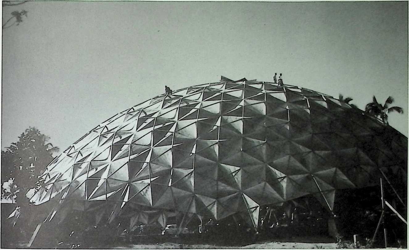
Figure 3. This 1957 photo shows the completion of the first true aluminum panel geodesic dome al Kaiser’s Hawaiian Village on Honolulu's Waikiki Beach. The dome is still in use as a nightclub.
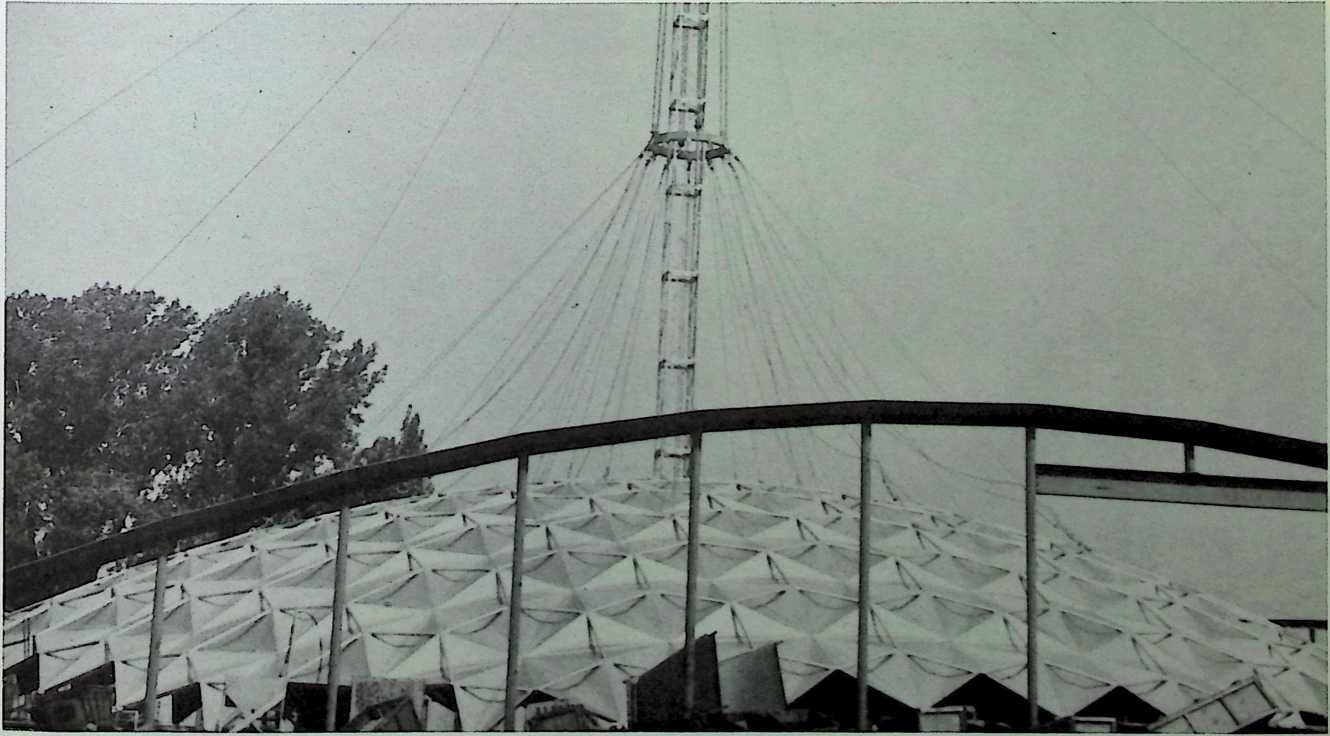
Figure 4. View of a 232-foot-span Temcor geodesic dome erection, working around a central lifting lower. Diamond-shaped structural panels on the ground have been braced with tubular aluminum struts anil are ready to he added to the next ‘‘ring’’ of dome construction. All assembly takes place safely al ground level.
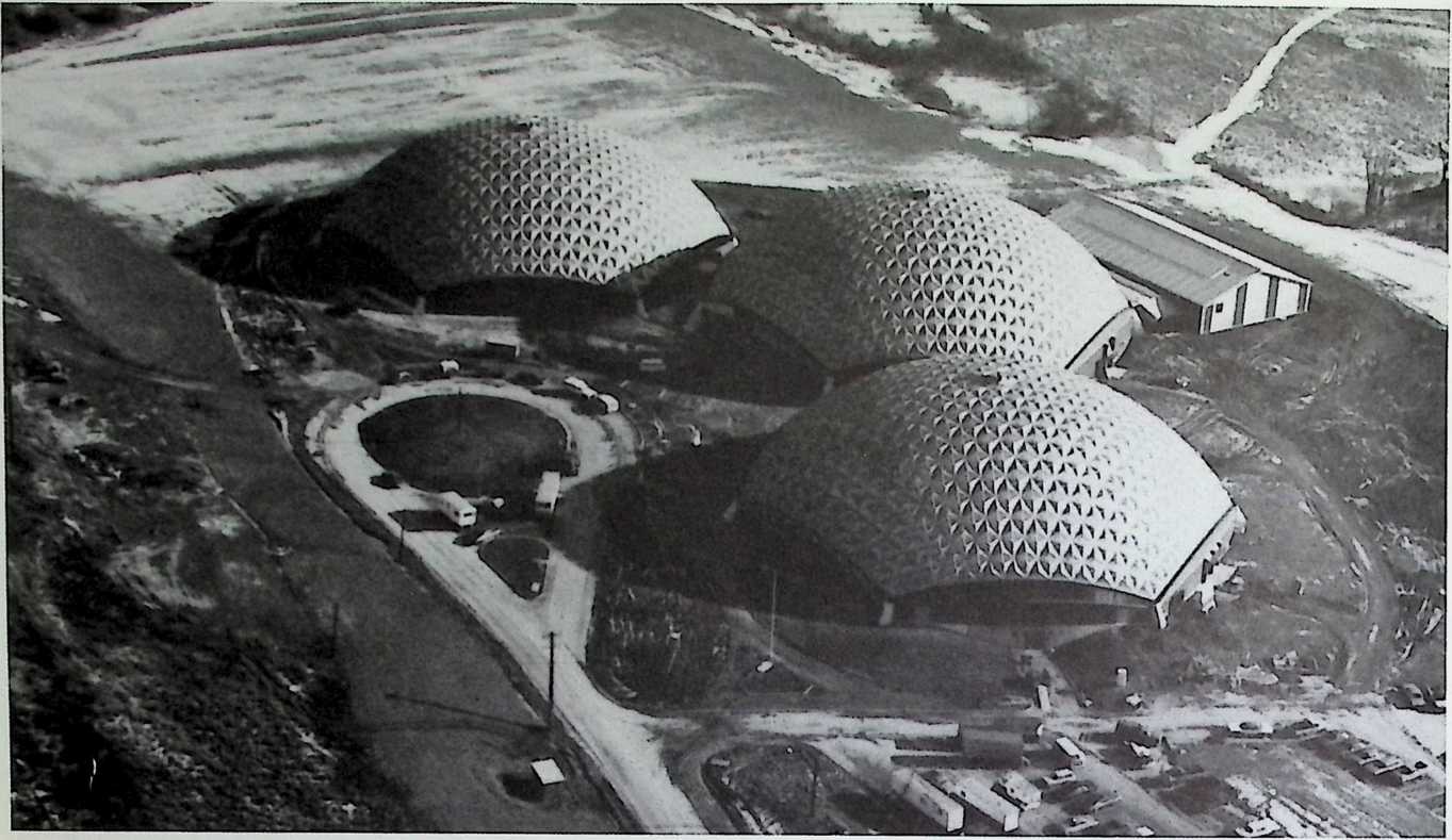
Figure 5. In this aerial view, the world’s first triple geodesic dome complex blends harmoniously into the snowy winter landscape al Elmira College in upstate New York. Flanking the gymnasium dome at center are the fieldhouse dome (left) and the hockey dome.
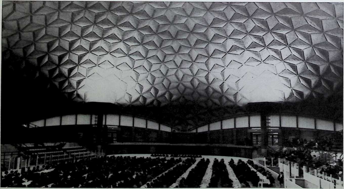
Figure 6. The dedication of the Elmira College triple geodesic dome complex took place on January 28, 1973. This photo taken during the community luncheon preceding the ceremonies shows details of the interior of the hockey dome, including the indirect lighting system that bounces light off the dome interior.
Figure 7. These basic dome geometries were studied by computer to determine their relative structure efficiency.
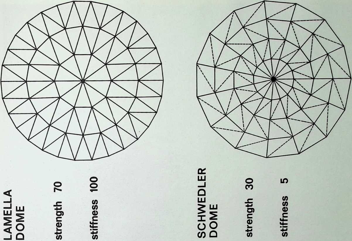
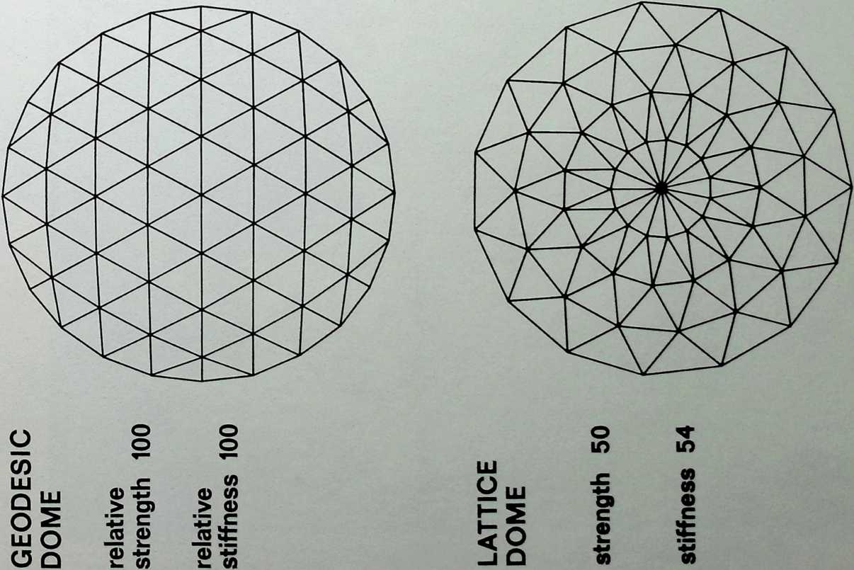
TEMCOR POLYFRAME
Figure 8. Temcor South Pole PolyFrame dome plan and elevation.
ELEVATION
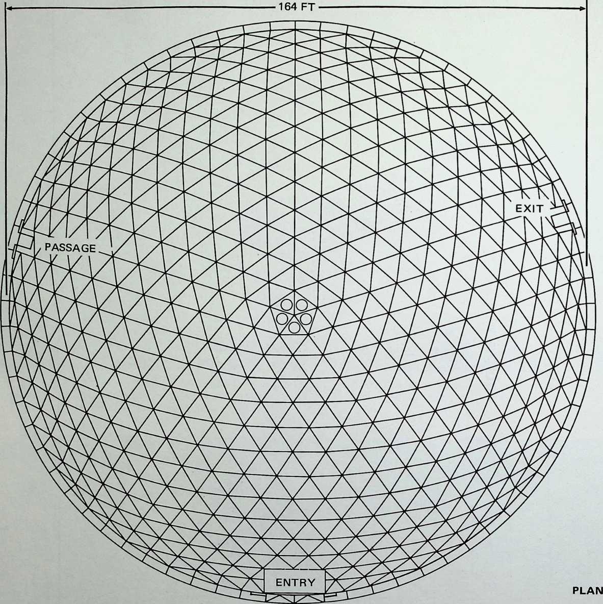
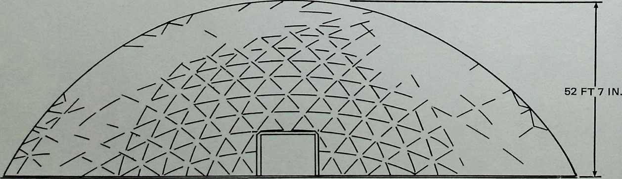
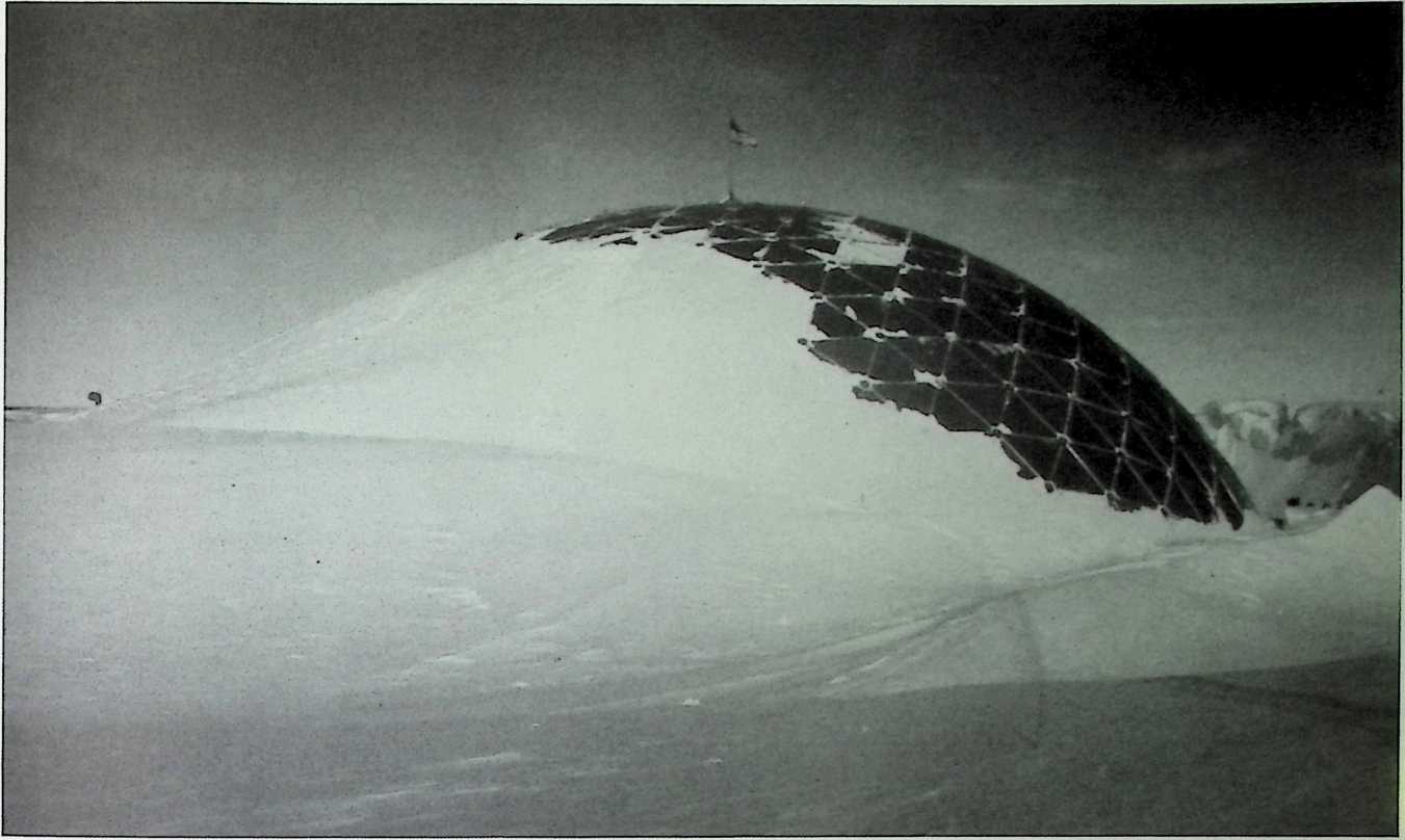
Figure 9. The all-aluminum PolyFrame dome had withstood ten years of sendee half buried in snow drifts when this photo was taken.
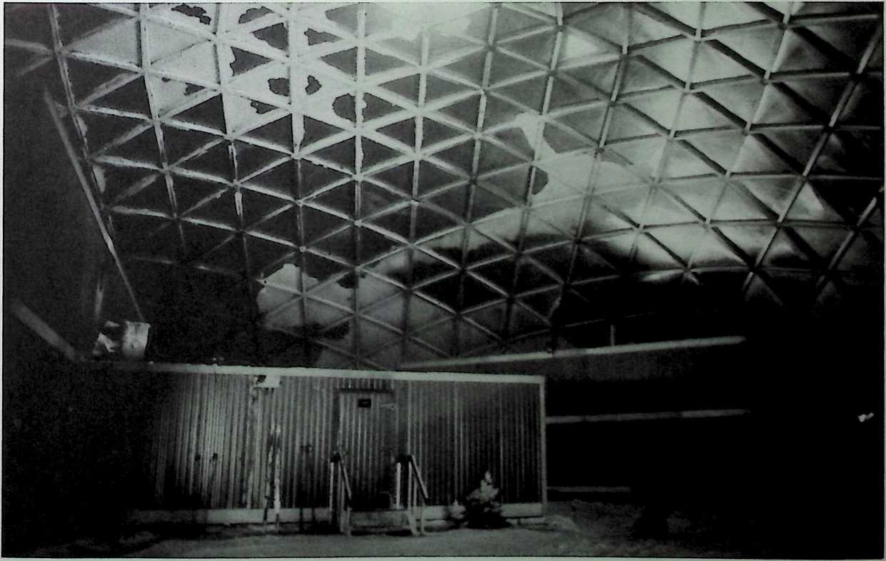
Figure 10. The 164-fool ‘‘weather-break’’ dome protecting the enclosed scientific station makes life at the South Pole livable.
PM - FEBRUARY 3
Figures 11 and 12. Photographs documenting the erection procedures of the Spruce Goose dome in Long Beach, California.
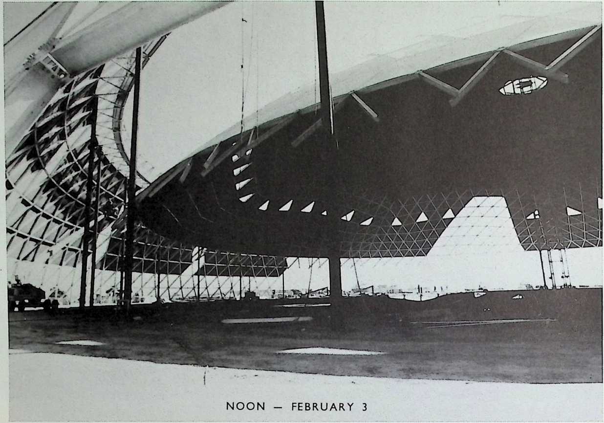
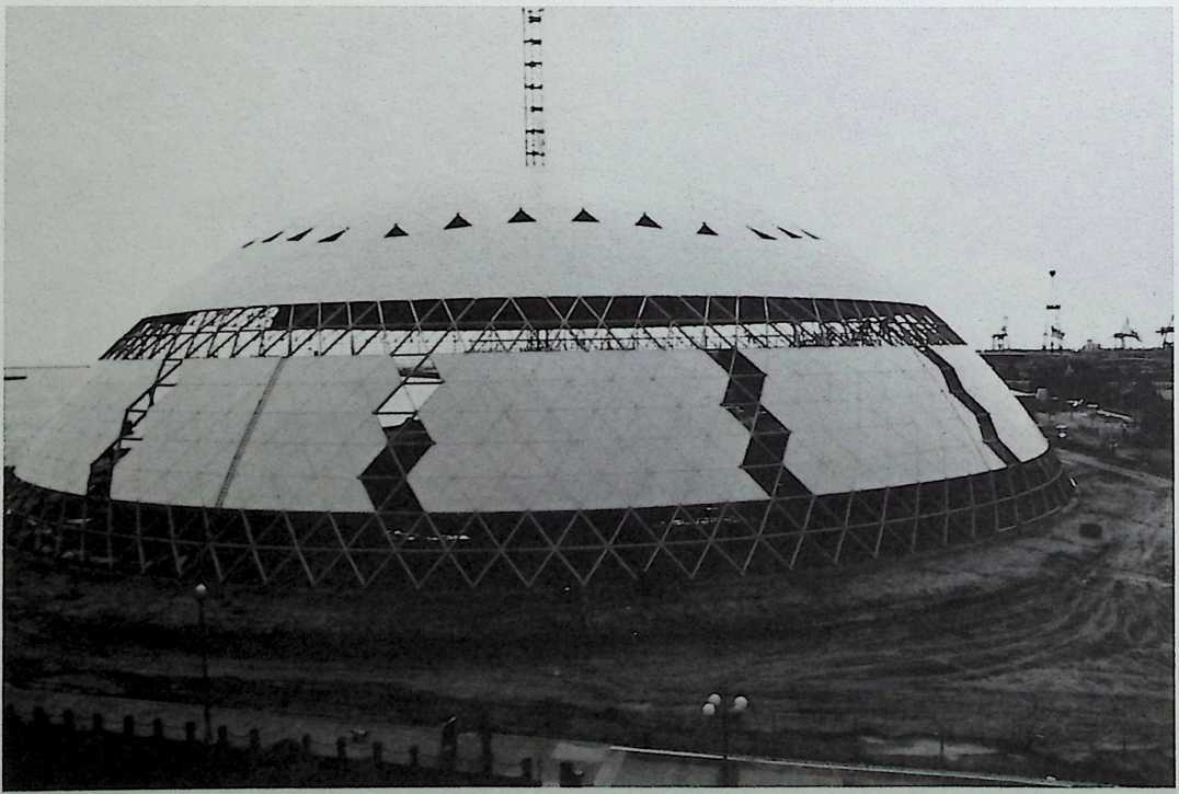
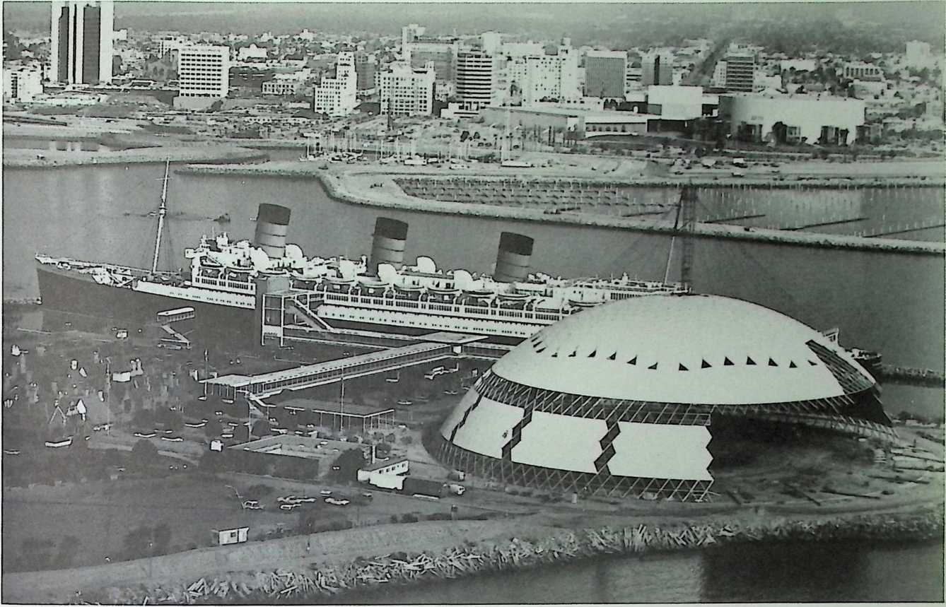
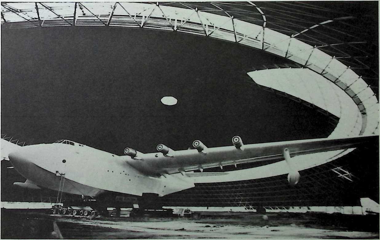
Figures 13 and 14. Photographs documenting the erection procedures of the Spruce Goose dome in Long Beach, California.
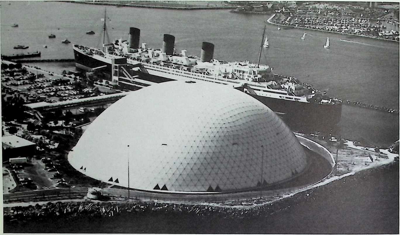
Figure 15. Completed in 1983, the 415-foot-diameter by 130-foot-high, all-aluminum, Temcor PolyFrame dome now provides a permanent home for the Spruce Goose aircraft in Long Beach, California.
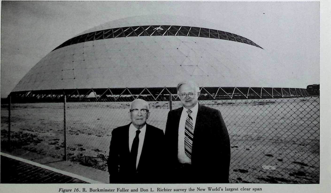
dome—the Temcor PolyFrame dome that houses the Spruce Goose.